Table of Contents
Advertisement
Quick Links
• Thank you for using the SmartWitness SVC400 Drive Recorder.
• Before using the SmartWitness, please ensure that you read
and understand this user guide.
• Please store this user guide in an easily accessible location.
• Before connecting and installing this Drive Recorder, please
refer to this instruction manual for proper operation.
PC Viewer Software can be downloaded at:
SVC400GPS
User Guide
support.smartwitness.com
v2.6.2
Advertisement
Table of Contents

Subscribe to Our Youtube Channel
Related Manuals for SmartWitness SVC400


Summary of Contents for SmartWitness SVC400
- Page 1 SVC400GPS User Guide v2.6.2 • Thank you for using the SmartWitness SVC400 Drive Recorder. • Before using the SmartWitness, please ensure that you read and understand this user guide. • Please store this user guide in an easily accessible location.
- Page 2 INFORMATION TO THE USER This equipment has been tested and found to comply with the limits for a Class B digital device, pursuant to part 15 of the FCC Rules. These limits are designed to provide reasonable protection against harmful interference in a residential installation.
-
Page 3: Safety Advice
SAFETY ADVICE CAUTION RISK OF ELECTRIC SHOCK DO NOT OPEN CAUTION: TO REDUCE THE RISK OF ELECTRIC SHOCK, DO NOT REMOVE COVER. NO USER-SERVICEABLE PARTS INSIDE. REFER SERVICING TO QUALIFIED SERVICE PERSONNEL. Please make sure you follow the safety advice/instructions given in the user guide. Caution RISK OF EXPLOSION IF BATTERY IS REPLACED BY AN INCORRECT TYPE. -
Page 4: Gps Reception
GPS Reception Activate the product in an area without large buildings to improve GPS reception. The commercial purpose GPS has the average rage error of more than 15 meters and the range error could be more than 100 meters due to environmental conditions like buildings, roadside trees etc. The temperature range for optimum operation of the GP S receiver in your car is -10 ~ 50°C. - Page 5 CONTENTS You should have a set of the following items with each SVC400 order. 1. SmartWitness SVC400 recorder 2. 32GB SD memory card (PC Viewer software is on the provided SD card.) 3. GPS Antenna module 4. Remote / Panic Switch 5.
- Page 6 CONTENTS cont’d You may have one or more of the following items with your SVC400 order. 11. SVA030-S -Interior Facing Camera -Weatherproof, can be mounted outside -Plugs in to “Cam 1-3” input 12. SVA041-S -Wide Angle Forward Camera -Plugs in to “Cam 1-3” input 13.
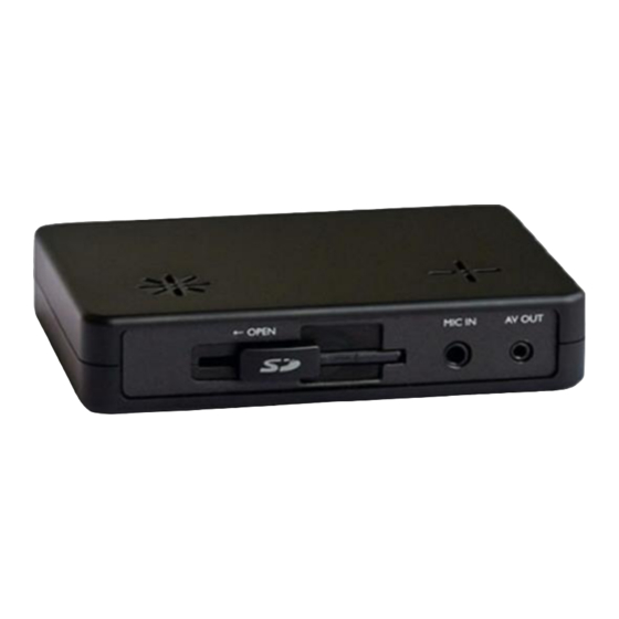
- Page 7 INTRODUCTION FRONT Audio/Video Output Camera 3 SD Door External MIC input SD Slot Input REAR BUZZER Internal Microphone Remote Control Input Power Input & GPS Input 12V Alarm Input Triggers Rear View Camera 1, 2 Input (Turn left, Turn right, Camera 4 Input Brake, Speed pulse)
-
Page 8: Remote Controller
INTRODUCTION REMOTE CONTROLLER Record LED BLUE LED SHUTTER BUTTON Error LED RED LED PLAY BUTTON PANIC BUTTON Audio Video Output Cable (Used only if connecting an LCD Display in the vehicle) Audio out 1 Video out 1 Video out 2 NOTE: The same screen will be shown through the Video out 1 &... - Page 9 INTRODUCTION Power & Car Signal Input Black (Ground) Red(+) Yellow (12V Alarm input) BLUE (5V Alarm output) FUSE 250V 3A White (Speed pulse) Green (12V Alarm input) **Blue, Yellow, Green, & White cables pulse are optional. Only power (red) and ground (black) are required.
-
Page 10: Hardware Installation
Screw holes for mounting 3) Install the interior and exterior cameras with 3M dual sided adhesive to the windshield as seen below. Ch 1-3 provide 5V power to all Smartwitness camera models ending in “-S” Interior Camera Exterior Camera... - Page 11 Cables should enter through rear of the locking case. Make sure cables go through this opening 6) Connect all cables to SVC400 Recorder (see pg 13 for additional Rear camera & LCD configuration) Power Input & External Mic input...
- Page 12 HARDWARE INSTALLATION cont’d 7) After all cables are inserted into recorder, you can connect the optional 12V Alarm input triggers (yellow & green only) Black (Ground -) BLUE (Alarm1 – 5V output) (Power +) Yellow (Alarm3 – 12V input) White (Speed pulse) Connects to VSS input Green (Alarm2 –...
- Page 13 HARDWARE INSTALLATION cont’d * Connecting Rear backup camera to SVC400 * Connecting LCD Monitor to SVC400...
- Page 14 Remote Controller LED status Indicators Blue Status Initial Power on Booting ON/OFF ON/OFF Pre Event recording Continuous recording ON/OFF Event recording Before Quickly Overwriting Event recording during continuous ON/OFF recording mode. (5seconds) Quickly ON/OFF SHUTTER recording Quickly Pre Event recording Continuous recording ON/OFF Event recording...
-
Page 15: Automatic Start
FUNCTION (MAIN UNIT) Automatic start Make sure that peripherals, including cameras, are properly connected. Turn on the vehicle power, SVC400 will automatically start. (Use the power cable provided.) Notice : The unit will not start recording immediately after the power is turned on. -
Page 16: Video Loss
The red LED will be turned on when: 1) There is an SD card error 2) The SVC400 is powered on and during the boot-up time (20 sec – 1 min after power on) 3) The “Panic” recording folder is full and needs to be purged... -
Page 17: Operation
2. Blue LED & Red LED will turn on and slowly blink simultaneously. After boot is complete, the Blue LED will remain on. Blue LED light means SVC400 is now ready for the event recording or has started the Normal recording (Continuous recording). - Page 18 It will mark the panic area by [PANIC] button in the continuous recording file which can be easily searched for during playback. SNAPSHOT RECORD BY SHUTTER BUTTON Press [SHUTTER] button. Then SVC400 will take a snapshot of 1 image with 5seconds audio with one short “Beep” sound.
- Page 19 SOFTWARE USER GUIDE SVC400 PC Viewer Guide [PC SYSTEM REQUIREMENT] Recommended PC specifications for PC Viewer software Windows 2000, Windows XP Windows Vista, Windows 7 Pentium4 2.6GHz or higher 512MB or higher Interface SD Memory Card Reader Install 20MB or higher...
-
Page 20: Pc Software Installation
3. Double click [SETUP.EXE] in the [pcsw] folder. 4. Select the language and then follow the dialog box. 5. The “PCViewer” icon will be displayed on your desktop. NOTE: To Un-install the “PC Viewer SVC400” Open the “Control Panel” Select [remove program] and remove [PC Viewer SVC400]... - Page 21 Connecting SD card 1. Insert SD card into your PC. 2. Run “PC Viewer SVC400” 3. Select [File] and then click “Select Data Folder” or Click [OPEN] button [OPEN] button 4. Select SD memory card folder at the folder select window and click “OK”.
- Page 22 Apply your Drive Recorder Settings 14. Click [Drive Recorder Settings] icon for setup. [Drive Recorder Settings] icon Caution Before clicking Init SD card button or before changing the Record Mode make sure to backup the SD card data first. All normal recording data or all event recording data in SD card will be automatically deleted to make free space on the SD card.
- Page 23 To use Motion Detection as an Event, check “Motion” box per camera. Normal Mode: Continuous recording will automatically Record Mode start after booting the SVC400. Event Mode: Recording by Motion Detection, G-sensor, Alarm1~3 or [PANIC] button. Dual Mode: Continuous recording will automatically start after booting and make a separate event recording file when there is an event.
- Page 24 Drive Recorder Settings – Resolution & Frame Rate Resolution PAL: 720x576, 720x288 NTSC: 720x480, 720x240 Frame Rate 1 Camera supports 1~25 fps@ 720x576, 1~25 fps @ 720x288 1 Camera supports 1~30 fps@ 720x480, 1~30 fps @ 720x240 2 Cameras supports 1~12 fps @ 720x576, 1~25 fps @ 720x288 2 Cameras supports 1~15 fps @ 720x480, 1~30 fps @ 720x240 3 Cameras supports 1 ~ 8 fps @ 720x576, 1~12 fps @ 720x288...
- Page 25 Drive Recorder Settings – Alarm Triggers To record the car signal with video, set the Alarm configuration as below, To use the Alarm as an Event trigger, (i.e.: so Event recording will start when a door is open or Meter is on) set the Alarm configuration as below, To use the Alarm as a changing live Display trigger, set the Display configuration, G-Sensor setting If G-sensor sensitivity value is too...
- Page 26 To use the playback function on the recorder. To record the exact time, this time zone setting is important. Once you set the time zone, the SVC400 automatically synchronizes time with GPS satellites. (Manual time setting is also available). Select GPS Record Time (the total log file size)
- Page 27 If you don’t know the speed pulse type of your car, select “Reset” and drive for more than 30 minutes. “Reset” will automatically detect the car pulse type. The SVC400 will compare the speed pulse and GPS speed and automatically set your car pulse type.
- Page 28 Drive Recorder Settings Initialize SD card: This prepares the SD card for use with the SVC400 system. All data will be deleted and the set the configuration of Drive Recorder will default to the factory settings. Delete Record Data : All data will be deleted.
- Page 29 PC VIEWER SETTINGS To set PC Viewer select [File] and then click” PC Viewer Setting” This setting is for the PC Viewer software itself. To set the recorder, refer to page 27. The ‘date’ formats and ‘speed’ unit will be set automatically according to the PC Windows setting.
-
Page 30: File Loading
FILE LOADING Check the file from the list using mouse or click [All] button. And then click [Load] button. Check the file [All] Button [Load] Button All recordings and snapshot files will appear the file area under the tab: The Event file list recorded by G-sensor Motion detection, or Alarm1~3. The Panic file list recorded by pressing the [PANIC] button. -
Page 31: Playback Screen
PLAYBACK SCREEN [NOR]: Normal Recording [G-Sensor]: Event Recording Display frame/Total frames number Playback position indicator Event data search button is enabled when playing back Normal The Yellow mark indicates there is an recorded files. Event triggered by the G-sensor, Alarm1~3 or the [PANIC] button. - Page 32 PLAYBACK Playback speed 6. Click [PLAY] button for playback. Date & Time CH1 CH2 CH3 Volume Drag & Move the white line to move the playback position. Playback buttons X2, 4, 8, 16 X0.5, 1 X0.5, 1 X2, 4, 8, 16 Fast Reverse Reverse Play...
- Page 33 Saving JPG files & AVI files Pause the playback and click ‘Save Image’ icon to make a JPG file. ‘Save Image’ icon Pause the playback and Click ‘Save AVI’ icon to make an AVI file. ‘Save AVI’ icon...
-
Page 34: Print Report
Print Report 11. Pause the playback and click ‘Print Image’ icon. Print image icon Input [Print Title] & [Print Comment] using Keyboard. Total Print Comment window allows up to 7 lines total. - Page 35 Create & Print Reports 12. Click [Print] button in the print preview windows for printing. [Print Title] & [Print Comment] & G-sensor graph & map will be printed on the first page. Click [ 2x2 ] and then click [Print] to print 4 images in one page. To print CH1~3 together select 1frame only.
-
Page 36: Data Backup
Data Backup 13. Click [Backup] icon to backup the files to the PC. [Backup] icon Check & Load [Event], [Normal], [Panic] [Log] & [Memo] data first, before clicking the [Backup] icon. The selected files will be listed in the correlating backup windows. -
Page 37: Log File Playback
LOG FILE PLAYBACK 16. Select [LOG] tab windows and then check the log from the log list using mouse or click [Check All] button. Then click [Load] button. LOG DATA will be recorded during driving even if there are no events. The total log data size can not exceed (1,240MB). - Page 38 GPS LOG TO KML CONVERTER (for Google Earth) Google Earth icon To see the whole route on Google Earth, select a log file and click Google Earth button. STEP1. Install the Google Earth on your PC. It is free of charge. (http://earth.google.com/ STEP2.
- Page 39 GPS LOG TO KML CONVERTER (for Google Earth) Google Earth lets you import the log data and save routes, add place marks (i.e. customer pick up locations, or other points of interest), add driving routes (to compare with the actual route taken, and it lets you save it all within Google Earth for easy and free data management! You can learn more about Google Earth here: http://support.google.com/earth...
- Page 40 Recording / Storage Time Table (NTSC) Note: This is a guideline only. Actual results may very depending on a variety of factors (Video signal, image, etc.)
-
Page 41: Technical Support And Warranty
Technical Support & Warranty TECHNICAL SUPPORT For Technical Support, please visit: http://support.smartwitness.com LIMITED WARRANTY This product is supplied with 1 year warranty. The Warranty excludes products That have been misused, (including accidental damage) and damage caused by normal wear and tear. In the unlikely event that you encounter a problem with... - Page 42 0678 SmartWitness USA 1016 Lunt Ave., Schaumburg, IL 60193 USA (312) 981-8774 www.smartwitness.com MADE IN KOREA © 2015 SmartWitness USA, LLC.
Need help?
Do you have a question about the SVC400 and is the answer not in the manual?
Questions and answers