
Related Manuals for Airlink101 AIC1620POE


Summary of Contents for Airlink101 AIC1620POE
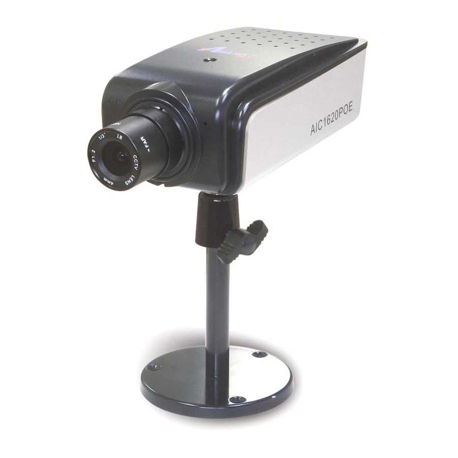
- Page 1 SkyIPCam1620 PoE MPEG4 3GPP Network Camera Model # AIC1620POE User’s Manual Ver. 1.0...
-
Page 2: Table Of Contents
CHAPTER 1 ...2 INTRODUCTION TO YOUR CAMERA ...2 1.1 Checking the Package Contents ... 2 1.2 Getting to Know Your Camera ... 2 1.3 Features and Benefits ... 4 1.4 System Requirements ... 5 1.5 Applications of the Camera ... 6 CHAPTER 2 ...7 HARDWARE INSTALLATION ...7 2.1 Connecting Your Camera to LAN... -
Page 3: Chapter 1
HAPTER NTRODUCTION 1.1 Checking the Package Contents Check the items contained in the package carefully. You should have the following: One SkyIPCam1620 PoE MPEG4 3GPP Network Camera One AC Power Adapter One Wall Mount Kit One GPIO & RS485 Adapter One Ethernet Cable (Cat.5) One Setup CD One Quick Installation Guide... -
Page 4: Rear View
Rear View GPIO and RS485 is used to connect the external devices. Ethernet Cable Connector* connects the network cable, which supports the NWay protocol so that the camera can detect the network speed automatically. * The camera’s Ethernet port supports IEEE 802.3af Power-over-Ethernet (PoE) standard that enables DC power to be supplied to the camera using wires in the connecting twisted-pair cable. -
Page 5: Features And Benefits
1.3 Features and Benefits Thank you for purchasing the SkyIPCam1620 PoE MPEG4 3GPP Network Camera, a standalone system that can be connected directly to an Ethernet or Fast Ethernet network. With MPEG4 image compression technology, you can record streaming video that utilizes high quality images to your hard drive, enable motion detection and set up automated e-mail alerts for security. -
Page 6: System Requirements
Multiple Applications Supported Through the remote access technology, you can use the cameras to monitor various objects and places for your own purposes. For example, babies at home, patients in the hospital, offices and banks, and more. The camera can capture both still images and video clips, so that you can keep the archives and restore them at any time. -
Page 7: Applications Of The Camera
1.5 Applications of the Camera The SkyIPCam1620 can be applied in multiple applications indoor, including: Monitor local and remote places and objects via Internet or Intranet. Capture still images and video clips remotely. Upload images or send email messages with the still images attached. The following diagram explains one of the typical applications for your camera and provides a basic example for installing the camera. -
Page 8: Chapter 2
HAPTER ARDWARE NSTALLATION 2.1 Connecting Your Camera to LAN Step 1 Assemble and attach the provided wall mount kit to the camera. Step 2 Connect one end of the provided Ethernet cable to the camera and connect the other end to one of the LAN ports on your router or switch. -
Page 9: Chapter 3
HAPTER AMERA ONFIGURATION 3.1 Setting up Your Camera Step 1 Insert the provided CD into your computer’s CD ROM drive. Step 2 Click on Install Utility and Software when the autorun menu pops up on the screen. Note: If you do not see the autorun menu pops up on the screen, please go to your CD-ROM drive > UltraView folder >... - Page 10 Step 3 Click Install to install the utility. Step 4 Click Finish when installation finishes. - 9 -...
- Page 11 Step 5 Open SkyIPCam Utility by double clicking its icon on the desktop, or clicking Start, then go to (All) Programs > Airlink101 SkyIPCam UltraView > SkyIPCam Utility. Step 6 Click on Search to find the camera(s) on your network. Select the camera you wish to configure and click on Change IP.
- Page 12 Step 7 Please configure a unique static IP address for your camera. The IP address you configure must match with your local network setting. For example, if your router’s IP address is 192.168.1.1, and its subnet mask is 255.255.255.0, the IP address you assign to the camera must be 192.168.1.x, where x is a number from 2~254, but outside of the DHCP range (i.e.
- Page 13 Step 8 Select the Camera you wish to configure and click on Link. You can click on Search button if the camera does not show up in the list. Step 9 When you are prompted for the username and password, enter “admin” for both User name and Password, and click OK.
- Page 14 Step 10 The camera viewing window will appear. Click on Setup, then click on Smart Wizard. Step 11 Enter a name for your camera and a location. Create an admin password and enter into Admin Password and Confirm Password. It is suggested to change the admin’s password to protect your privacy.
- Page 15 Note Be sure to enter Primary/Secondary DNS addresses assigned by your ISP if you set up Static IP for the camera so that the Email alert / FTP uploading can function properly. Step 13 If you would like to set up email alerts that you can receive in the future, Please enter your email information here.
-
Page 16: Viewing Image Via Your Camera
3.2 Viewing Image via Your Camera Method A > Access Camera from SkyIPCam Utility Step 1A Open Airlink101 SkyIPCam Utility, select the camera you wish to connect to and click on Link button. Go to Step 3. Method B > Access Camera from Web Browser Step 1B If you assigned a static IP address for your camera, you may open the Web Browser on your computer. - Page 17 Step 3 Enter username and password, then click OK. The default username and password are both “admin” if you did not make any change to it at Step 9, Section 3.1. Step 4 Internet Explorer User: If this is the first time for your computer to view image from the web configuration page, you will be prompted to install the ActiveX Control.
- Page 18 Note If you are using Mozilla Firefox or Safari and you are not able to view any image, please make sure you have Java and Quick Time add-ons installed. - 17 -...
-
Page 19: Chapter 4
HAPTER SING ONFIGURATION You can access and manage the camera through the Web browser and the provided software application SkyIPCam UltraView. This chapter describes the Web Configuration, and guides you through the configuration of the camera by using the web browser. To open the Web Configuration page, please refer to Chapter 3.2, Viewing Image via Your Camera. - Page 20 Basic >> Date & Time Date & Time - TimeZone: Select the proper time zone for the region from the pull-down menu. - Synchronize with PC: Select this option and the date & time settings of the camera will be synchronized with the connected computer.
- Page 21 - User Name: Enter the user’s name you want to add to use the camera. - Password: Enter the password for the new user. When you are finished, click Add/Modify to add the new user to the camera. To modify the user’s information, select the one you want to modify from UserList and click Add/Modify.
-
Page 22: Network Settings
4.2 Network Settings The Network menu contains three sub-menus that provide the network settings for the camera, such as the IP Setting, DDNS Setting, and IP Filter. Network >> Network IP Setting This item allows you to select the IP address mode and set up the related configuration. - DHCP: Select this option to allow your router dynamically assign an IP address to your camera. - Page 23 DDNS Setting With the Dynamic DNS feature, you can assign a fixed host and domain name to a dynamic Internet IP address. To set up the DDNS: 1. Check Enable checkbox to enable this feature. 2. Select a DDNS Provider from the pull-down list. Please go to the DDNS provider’s website and register a DDNS account, then you will obtain the information required below.
- Page 24 Network >> IP Filter The IP Filter setting allows the administrator of the camera to limit the users within a certain range of IP addresses to access the camera. Disable: Select this option to disable the IP Filter function of the camera. Accept - Start/End IP Address: Assign a range of IP addresses that are allowed to access the camera by entering the Start IP address and End IP address options.
-
Page 25: Setting Up Video & Audio
4.3 Setting up Video & Audio The Video & Audio menu contains three sub-menus that provide the video and audio settings for the camera. Video & Audio >> Camera Image Setting - Brightness: Adjust the brightness level from 0 ~ 100. - Contrast: Adjust the contrast level from 0 ~ 100. - Page 26 Video & Audio >> Video MJPEG - Video Resolution: Select the desired video resolution from the three formats: VGA, QVGA and QQVGA. The higher setting (VGA) obtains better video quality while it uses more resource within your network. - Video Quality: Select the desired image quality from five levels: Lowest, Low, Medium, High, and Highest.
- Page 27 If you use a 3G mobile device, you can also view the real-time streaming image captured by the camera on your phone with the default (built-in) player by entering the RTSP link: of the camera)/3gp. NOTE Your mobile phone and the service provider must support 3G data service. Please contact your service provider when you are failed to use this service.
- Page 28 Includes Date & Time: Check this option to display the date & time stamp on the live view image. Include Text: Check this option and enter the text (i.e. Camera Room A01) you wish to display on the live view image. Enable Opaque: Check this option to set a black background to the displayed date &...
-
Page 29: Event Server
4.4 Event Server The Event Server menu contains three sub-menus that allow you to upload images to FTP, send emails that include still images, and store video clips, still images to a network attached storage (NAS). Event Server Setting>> FTP - Host Address: Enter the IP address of the target FTP server. - Page 30 Event Server Setting >> Email Email - SMTP Server Address: Enter the mail server address. For example, mymail.com. - Sender Email Address: Enter the email address of the user who will send the email. For example, John@mymail.com. - Sender User Name: Enter the user name to login the mail server. - Sender Password: Enter the password to login the mail server.
- Page 31 Event Server Setting >> NAS Network Storage - Samba Server Address: Enter the IP address of the Network Storage server. - Share: Assign the folder on the Network Storage server to share the files to users. - Path: Assign the path for uploading the files on the Network Storage server. For example, /Test/. - User Name: Enter the user name to login into the Network Storage server.
-
Page 32: Motion Detect
4.5 Motion Detect *This function can only be configured in Windows Internet Explorer. The Motion Detect menu contains the command and option that allow you to enable and set up the motion detection feature of the camera. The camera provides two detecting areas. To enable the detecting area, select Window 1 or 2 from the pull-down list, and then check Enable. -
Page 33: Event Config
4.6 Event Config The Event Configuration menu contains five sub-menus that provide the commands to configure event profiles. Event Configuration >> General Setting - Snapshot/Recording Subfolder: You can assign a given sub-folder for captured file. Otherwise, leave this option blank to use the default setting. - Network Storage Recording Time Per Event: Limit the recording time while you are using the Network Storage solution. - Page 34 Event Configuration >> Schedule Profile This sub-menu displays the scheduled profile(s). To configure a new profile, click Add and then enter a descriptive name for the profile in the prompt dialog window. After entering the profile name, click OK and the profile is added to the Schedule Profiles list.
- Page 35 Event Configuration >> Schedule Trigger You can configure the schedule for trigger function of the camera individually by Email, FTP, and NAS. Select the Enable option on each item, and then select a Schedule Profile from the pull-down list and set the Interval time.
- Page 36 - Schedule Profile: Select a schedule profile from the pull-down list. - Action: Set the Trigger Out function or select the destination that the captured images will be sent to: Record to Network Storage, Send Email, or FTP Upload. - 35 -...
-
Page 37: Tools
4.7 Tools The Tools menu provides the commands that allow you to restart or reset the camera. You can also backup and restore your configuration, and upgrade the firmware for the camera. Factory Reset Click Reset to restore all factory default settings for the camera. System Reboot Click Reboot to restart the camera just like turning the device off and on. - Page 38 4.8 RS-485 The RS-485 menu provides the control settings for external device through the I/O port. Check the Enable option and complete the required configuration to use the RS-485 function of the camera. Popular Protocol Setting: Select this option and then select a protocol. When you enable the RS- 485 function of the camera, it will display the additional control buttons on the live view screen (as shown on the next page).
-
Page 39: Rs-485
About the Control Buttons After enabling RS-485 function, the control panel will appear on the Live View window. Control Buttons of RS-485 - Left/Right/Up/Down/Home buttons allow you to move the camera lens position. Clicking the Home (center) button will move the camera lens to the assigned home position. Left - Click the Number button (1~8) to move the camera lens to the preset position immediately. -
Page 40: Information
Information The Information menu displays the current configuration and events log of the camera. Information >> Device Info Display the Basic, Video & Audio, and Network settings of the camera. Information >> System Log The Logs table displays the events log recorded by the system. - 39 -... -
Page 41: Chapter 5
HAPTER SING 5.1 Starting the Program To start UltraView Pro, click Start UltraView. Alternately, you can start the program by simply double-clicking the program icon on the desktop of your computer. On the login window, enter the User name/Password and click OK to login. If this is the first time you start the program and login, use the default user name / password: NOTE For security purpose, you are highly recommended to change the default user name and... -
Page 42: Main Window And Item Feature
5.2 Main Window and Item Feature When you start and login to UltraView, the Main window will display as below: The Main window provides you with the information on operating the system, as well as the control panel such as the Quick Launch buttons, and so on. NOTE UltraView Pro requires the resolution setting up to 1024 x 768. - Page 43 Camera View Mode buttons in this area allow you to switch the camera view mode. Button Function Display the connected camera(s) in single camera view mode. Display the connected camera(s) in quad view mode. Display the connected camera(s) in 3 x 3 grid view mode.
- Page 44 Navigation buttons allow you to move the camera lens position. Clicking the Home (center) button will move the camera lens to the assigned home position. **AIC1620POE does not support Pan/Tilt function. The Patrol/Stop buttons are used to enable/disable the swinging function of the camera. Click Patrol to start patrolling through the preset positions once.
-
Page 45: Accessing The Camera
5.3 Accessing the Camera Before you can access the camera, you have to add the camera to the system. Adding a Camera 1. Click the button and select Device Setting to display the Device Setting window. 2. Click New. 3. Click Device Search to search the camera(s) within your network. - 44 -... - Page 46 The password for accessing the camera will not be displayed. Stream Select the stream type as MPEG4, MJPEG, or H.264. (H.264 is not supported by AIC1620POE) Record Select Yes or No to set up recording function of the camera. Preview...
- Page 47 Disconnect to stop previewing. You cannot set the motion detection area while adding the new camera. To set the motion detection area of the camera, select the desired camera and click the Modify button on the Device Setting window. See the following section for more information. 6.
- Page 48 Editing / Deleting a Camera Since you have added camera(s) to the system, you can select one to edit or remove. 1. On the Device Setting window, the connected camera(s) will be displayed in the Device List. 2. To delete the camera: select the desired one and then click Remove. When prompted, click Yes and then select OK to confirm deletion.
- Page 49 Viewing Image of the Camera Since you have added camera(s) to the system, the image of the selected camera(s) will be displayed on the Live View Window automatically. You can view a maximum of 32 cameras simultaneously. Additionally, you can select one-camera or other view mode to display the video from the Camera View Mode buttons.
-
Page 50: Recording / Playing Video
5.4 Recording / Playing Video Enabling / Disabling Recording While you are adding/editing the camera, you can enable the recording function for the camera by selecting the Record option. Click Save after you finish setting. Alternately, you can set all cameras to start/stop recording when you connect multiple cameras. Click the button and select All Continuous Recording to set all cameras to start recording, or select Stop All Recording to set all cameras to stop recording. - Page 51 Configuring the Recording Settings The default directory for saving the recorded video files is “C:\”. You can change the target folder for saving the files in the Record Setting option. 1. Click the button and then select Record Setting. 2. To assign the target folder for saving the recorded files, click the Browse button next to the Recording Path option, and then select the desired directory.
- Page 52 Click the button to display the Schedule Configuration window, which allows you to configure the recording schedule. 1. Click New, and then enter the Schedule Title. 2. Select the checkboxes below the Schedule Title to set the time to record video. One checkbox stands for 30 minutes of recording time.
- Page 53 NOTE Divx/Xvid codec is required for the system to play the video files. If the video clips cannot be displayed in the Playback window normally, click the following path to download and install the required component: http://download.divx.com/divx/DivXInstaller.exe 1. Click the button to display the Playback window.
-
Page 54: Configuring The Emap View Setting
5.5 Configuring the eMap View Setting button and select View Setting to configure the camera view setting of eMap mode. Click the eMap refers to the geography and device scope of the UltraView Pro, which visually presents the devices in your security system. It uses a background of the area (e.g. a picture or a map) as the interface for monitoring. - Page 55 Click Save after you complete the settings. 4. On the following window, you can assign the camera position in the eMap. Click the Camera Location button to display the Edit window. Select the camera from the Camera List, and then click the mouse on the desired position of the map. The camera icon will be displayed on selected position of the map.
- Page 56 5. When completed, click Save. Click Back to go back to the Main window. 6. To view from eMap: a. Click the button and select eMap View. - 55 -...
- Page 57 b. Select the map from the eMap Name list. c. Click the camera icon, the camera window will then pop up to display the image on the spot. - 56 -...
- Page 58 Editing / Deleting the eMap 1. Click the button and select View Setting. 2. To edit the eMap: In the eMap List, select the desired map and click Modify. The map’s information will be displayed, where you can change the map’s information and then click Save when completed.
-
Page 59: Configuring The System
5.6 Configuring the System User Management Click the button and select Account to change the administrator password for the UltraView software. Enter the Current password, and then enter the new password twice (in the Type new password and Retype password boxes). When completed, click Save. - 58 -... -
Page 60: Event Configuration
5.7 Event Configuration Configuring Event Trigger Click the button and select Event Trigger to configure the trigger out function of the camera. 1. On the Event Trigger window, select the desired camera from the Camera List. 2. Do one of the following: SMTP: Select this option and enter the Subject and Message, the system will send an email message to the selected user(s) in the Address Book List. - Page 61 Setting up Event Server Click the button and select Event Server to configure the SMTP server, so that you can send emails that include still images as notification. Select the Enable SMTP option to start the email service of the system. When you enable the service, you have to complete the following settings.
-
Page 62: Sending Email Notification
Sending Email Notification Click the button and select Address Book to assign the user to the Address Book of the camera. The user will receive a real-time notification from the system while triggering out. 1. On the Address Book window, click New. 2. -
Page 63: Changing System Language
5.8 Changing System Language Click the button and select language to change the displayed system language. On the Language screen, select the preferred language (English, Traditional Chinese, or Simplified Chinese) and click Save. - 62 -... -
Page 64: Terminating Operation
5.9 Terminating Operation When you have finished operating, click the button and select Logout to logout the system or Close to exit the program. - 63 -... -
Page 65: Chapter 6
HAPTER PPENDIX A.1 Specification Image Sensor Sensor Type: 1/3” Color CMOS • Sensor Resolution: 640 x 480 pixel • Minimum Illumination: 0.5 Lux • Lens Lens Type: CS-Mount • View Angle (Diagonal): 72 degree • Focal Length: 4mm • Aperture (F/No.): F1.2 •... -
Page 66: Gpio Terminal Application
A.2 GPIO Terminal Application Typically used in association with programming scripts for developing applications for motion detection, event triggering, alarm notification via e-mail, and a variety of external control functions. The 6-pin I/O Terminal Block is located on the rear panel and provides the interface to: a photo-coupled switch output, a photo-coupled input, and RS-485 interface. -
Page 67: Bandwidth Reference Guide
A.3 Bandwidth Reference Guide MPEG4 Frame Resolution rate Lowest (fps) QQVGA QVGA MJPEG Resolution Lowest QQVGA QVGA 11.2 Bit rate (Kbit/s) Normal High Highest 1024 1024 2048 Image size (KB) Normal High highest 24.3 - 66 -... -
Page 68: Glossary Of Terms
A.4 Glossary of Terms NUMBERS 10BASE-T 10BASE-T is Ethernet over UTP Category III, IV, or V unshielded twisted-pair media. 100BASE-TX The two-pair twisted-media implementation of 100BASE-T is called 100BASE-TX. ADPCM Adaptive Differential Pulse Code Modulation, a new technology improved from PCM, which encodes analog sounds to digital form. - Page 69 Ethernet The most popular LAN communication technology. There are a variety of types of Ethernet, including 10Mbps (traditional Ethernet), 100Mbps (Fast Ethernet), and 1,000Mbps (Gigabit Ethernet). Most Ethernet networks use Category 5 cabling to carry information, in the form of electrical signals, between devices. Ethernet is an implementation of CSMA/CD that operates in a bus or star topology.
- Page 70 It is an object-oriented multi-thread programming best for creating applets and applications for the Internet, Intranet and other complex, distributed network. Local Area Network a computer network that spans a relatively small area sharing common resources. Most LANs are confined to a single building or group of buildings. MJPEG MJPEG (Motion JPEG) composes a moving image by storing each frame of a moving picture sequence in JPEG compression, and then decompressing and displaying each...
- Page 71 network protocol. RJ-45 RJ-45 connector is used for Ethernet cable connections. Router A router is the network software or hardware entity charged with routing packets between networks. RTP (Real-time Transport Protocol) is a data transfer protocol defined to deliver live media to the clients at the same time, which defines the transmission of video and audio files in real time for Internet applications.
-
Page 72: Technical Support
* Actual data throughput will vary. Network conditions and environmental factors lower actual data throughput rate. Specifications are subject to change without notice. All products and trademarks are the property of their respective owners. Copyright © 2011 AirLink101® Technical Support E-mail: support@airlink101.com Toll Free: 1-888-746-3238...
Need help?
Do you have a question about the AIC1620POE and is the answer not in the manual?
Questions and answers