
Related Manuals for Airlink101 AGSW2400


Summary of Contents for Airlink101 AGSW2400
- Page 1 Quick Installation Guide 24-Port 10/100/1000Mbps Green Switch Model# AGSW2400 Ver. 1A...
-
Page 2: Copyright Statement
Trademarks Copyright © 2011 Airlink101® Airlink101® is a registered trademark. All other trademarks belong to their respective proprietors. Copyright Statement No part of this publication may be reproduced in any form or by any means or used to make any derivative such as translation, transformation, or adaptation without permission from Phoebe Micro, Inc. -
Page 3: Hardware Interface
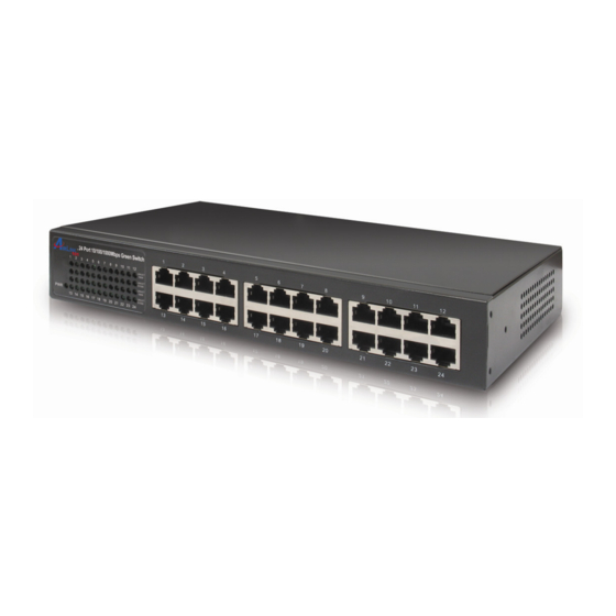
Introduction Congratulations on your purchase of the 24-Port 10/100/1000Mbps Green Switch! It is an easy-installed network switch which helps you to extend your network structure quickly and reliably. Purpose This Quick Installation Guide tells you how to install your Switch and how to connect it to your Ethernet network. Terms/Usage In this manual, the term “Switch”... - Page 4 1.2 Panel 1.2.1 Front Panel The front panel of the Switch consists of LED indicators, and 24 10/100/1000Mbps ports. The figure below shows the front panel of the Switch. Figure 1-1 Front Panel view of the Switch • 10/100/1000Mbps Ports (Port 1~24): These ports support 10/100/1000Mbps, and can operate in Half/Full Duplex transfer modes.
- Page 5 1.2.2 Rear Panel Figure 1-2 Rear Panel view of the Switch • AC Power Connector: Supports AC 100~240V, 50~60Hz. NOTICE: Do not cover or put anything on and surrounding the switch while the Switch is operating. 1.2.3 LED indicators information The front panel LEDs provide instant status feedback and help monitoring and troubleshooting when needed.
- Page 6 • POWER: Power Indicator Color POWER Green • Port 1~24 10/100/1000Mbps Status LEDs Color LINK/ Green 10/100M Color LINK/ Green 1000M Status Solid Blinking The Switch is power-on Status Solid Blinking respective port is The port is successfully transmitting or connected to receiving data 10/100Mbps...
-
Page 7: Technical Specifications
1.3 Technical Specifications Standards • IEEE 802.3 10BASE–T, IEEE 802.3u 100BASE–TX, IEEE802.3ab 1000BASE-T Gbit and IEEE 802.3x Flow Control Network Cables • Ethernet (10Base-T): Cables: 2-pair UTP Cat. 3, 4, 5, Twisted Pair (UTP). Up to 100m • Fast and Giga Ethernet (100/1000Base-T): 2-pair UTP Cat. - Page 8 Data Transfer Rate** • Ethernet: 10/20Mbps – Half/Full-Duplex • Fast Ethernet: 100/200Mbps – Half/Full Duplex • Giga Ethernet 1000/2000Mbps – Half/Full Duplex Physical and Environmental • Power Input: 100~240V AC, 50~60Hz • Operation Temperature: 0 °C ~ 40°C • Storage Temperature: -20°C ~ 70°C •...
-
Page 9: Installing The Switch
Installing the Switch The site where you place the switch may greatly affect its performance. When installing, take the following into your consideration. 2.1 Installation Follow the guidelines below to install the Switch: Install the Switch in a fairly cool and dry place. See the Technical Specifications for the acceptable temperature and humidity operating ranges. -
Page 10: Rack Installation
2.3 Rack Installation The Switch is rack-mountable and can be installed on an EIA 13-inch equipment rack. To do this, first install the mounting brackets on the Switch’s side panels (one on each side), secure them with the included screws, and then use the screws provided with the equipment rack to mount the Switch. -
Page 11: Connecting The Switch
Connecting the Switch This section describes how to connect the Switch to your 10/100/1000Mbps Ethernet network. 3.1 Connection Your network device (i.e. computer, switch, IP Camera, VoIP) can be connected to any port of the Switch via a two-pair UTP Category 5 Cable. If the LED indicators do not light up after making a proper connection, check your network device, the cable, the Switch conditions and connections. -
Page 12: Technical Support
Technical Support E-mail: support@airlink101.com Toll-Free: 1-888-746-3238* Web Site: www.airlink101.com * Free Voice Technical Support is only available within the hardware warranty (1-Year Limited Warranty from the date of purchase). Customer is required to provide invoice as purchase evidence. **Network conditions and environmental factors as well as network overhead can lower actual data throughput rate.
Need help?
Do you have a question about the AGSW2400 and is the answer not in the manual?
Questions and answers