Advertisement
Quick Links
SPECIFICATIONS:
Model ......................................... 6M HO LOOP
Frequency Range ....................... 50 To 50.3 MHz
Gain, Typical @ 11 ft. ................. 6.3 dBi @ 25 deg.
Gain, 2 Stack @ 40 & 52 ft. ....... 10.3 dBi @ 6 deg.
Polarity ...................................... Horizontal
Impedance ................................. 50 Ohms, Unbalanced
Power Handling. ......................... 800W, 1.5 kW stacked
FEATURES:
Our 6M HO Loop is the result of a continued development of reduced size, omni-directional horizontally polarized loop-style
antennas. This new design is easy to match in any situation. Performance is better than anything in its class and its design makes
it immune to nearly all weather conditions. Power handling is often a problem with small loops but this design can handle 800 watts
with ease and a stacked pair can easily handle 1.5 kW. The patterns contained in the manual will give you a good idea of how well
the 6M HO Loop will perform in your system.
As with all horizontally polarized antennas, performance is usually tied to height above ground but even at ten feet the HO Loop
yields an amazing 5.9 dBi at an angle of 27 degrees. Mounted on a vehicle at eleven feet above ground, the gain jumps to 6.3 dBi at
25 degrees. Stacked for base or portable use, twelve foot spacing is optimum. Note that the gain jumps over 3 dB for a stacked pair
of these unique antennas, yielding as much as 10.3 dBi!
Physically the HO Loop is 29.5 inches square with a wind area of just 0.1 square foot. The 3/8" diameter tubing keeps it light but
plenty rugged for mobile operation. Our precision machined aluminum feed block is sealed and potted with silicon gel for extreme
reliability and low loss. The feed block slides on the tubes for frequency adjustment and the shorting bar adjusts for a perfect match
into 50 ohm feedline. Two HO Loops can be stacked using a coaxial power divider.
Optional items include our line of lightweight aluminum mobile masts and our "Big-Foot" heavy duty magnetic base. We also
offer coaxial power dividers and phasing cables for stacking HO Loops.
M2 Antenna Systems, Inc. 4402 N. Selland Ave. Fresno, CA 93722
M2 Antenna Systems, Inc.
Model No: 6M HO LOOP
*Subtract 2.14 from dBi for dBd
Tel: (559) 432-8873 Fax: (559) 432-3059 Web: www.m2inc.com
©2015 M2 Antenna Systems Incorporated
Feed Connector .......................... SO-239
Mounting ..................................... 3/8-24 or 1-1/4"-2"
Vehicle Mounting Height ............ 30" or more
Stacking Distance ...................... 9ft to 12ft
Maximum Element Length .......... 29-1/2"
Wind Area ................................... 0.1 sq ft.
Weight ........................................ 2 lbs.
08/29/12
Rev.03
Advertisement

Related Manuals for M2 6M HO LOOP


Summary of Contents for M2 6M HO LOOP
- Page 1 FEATURES: Our 6M HO Loop is the result of a continued development of reduced size, omni-directional horizontally polarized loop-style antennas. This new design is easy to match in any situation. Performance is better than anything in its class and its design makes it immune to nearly all weather conditions.
- Page 2 6M HO LOOP ASSEMBLY OVERVIEW...
- Page 3 6M HO LOOP ASSEMBLY MANUAL 1. Slide on (1) support clamp and center it at 2-1/4” on to the white center insulator. Install a 1/4-20 X 1/4 set screw into support clamp block and tighten gently. 1. Insert the HO Loop tubes into the center insulator.
- Page 4 6M HO LOOP ASSEMBLY MANUAL 1. Install the 1/4-20 X 1/4” set screws in the feed block assembly and slide onto the tubes. Carefully align the HO Loop halves and tighten the set screws gently. 2. Install the 1/4-20 X 1/4” set screws in the shorting bar.
- Page 5 6M HO LOOP ASSEMBLY DETAILS 1. Attach the second support clamp on one end of the 3/8” support tube. Install 6-32 screw, locknut and the 1/4-20 X 1” bolt on the support clamp block. 1. Connect the other end of the support tube to the other support clamp block with the 6-32 screw and locknut .
- Page 6 6M HO LOOP BASE MOUNTING DETAIL...
-
Page 7: Basic Tuning
Note: Be sure to reverse one feed block to account for the 180° phase shift in the 6M HO Loop 2 Port Power Divider. See “Mounting and Stacking Options” for more information. - Page 8 MAST MOUNTING OPTIONS 36” MOBILE MAST (SOLD SEPARATELY) CUSTOMER SUPPLIED MAST (1-1/4” - 2” DIA.) SINGLE 6M HO LOOP PERFORMANCE HEIGHT ABOVE GAIN ANGLE OF GROUND RADIATION 8 FT 4.74 dBi 33° MOBILE 12 FT 6.54 dBi 22° MOBILE 30 FT 6.64 dBi...
- Page 9 STATION SYSTEM OF 2 STACKED AND PHASED 6M HO LOOPS PARTS NEEDED: (2) 6M HO LOOPS 6M HO LOOP 2 PORT POWER DIVIDER (OMITTED FOR CLARITY) Order online at http://www.m2inc.com CUSTOMER SUPPLIED MAST (1-1/4” - 2” DIA.) NOTE: A 180°...
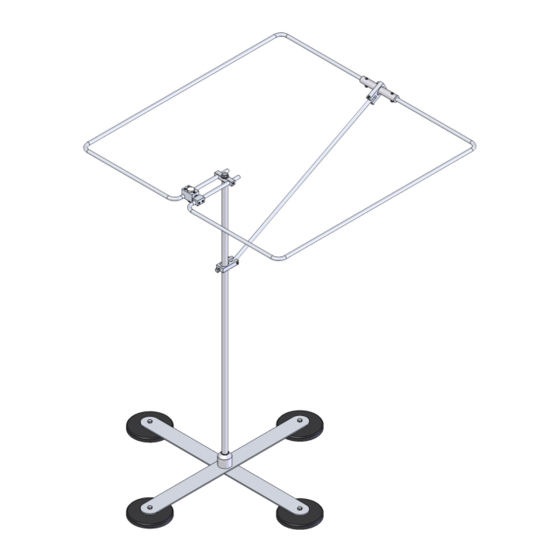
- Page 10 OF THE VEHICLE BODY, ADDITIONAL GUYING OR SUPPORT MAY BE NECESSARY. SHOWN IS AN EXAMPLE OF MOBILE HO LOOP MOUNTING (YOUR INSTALLATION MAY DIFFER) PARTS NEEDED 6M HO LOOP 36” ALUMINUM MAST “BIG-FOOT” MAGNET MOUNT Order online at...
- Page 11 6M HO LOOP PARTS & HARDWARE DESCRIPTION ..................QTY HOLOOP TUBE (BENT) 3/8” OD ............. 2 SUPPORT TUBE, 3/8” ................1 FEED BLOCK ASSEMBLY ..............1 SHORTING BAR, 1/2” X 1/2” X 2-1/2” ............. 1 CENTER INSULATOR, 3/4” UHMW ............1 SUPPORT CLAMP, 1/2”...
Need help?
Do you have a question about the 6M HO LOOP and is the answer not in the manual?
Questions and answers