Advertisement
Quick Links
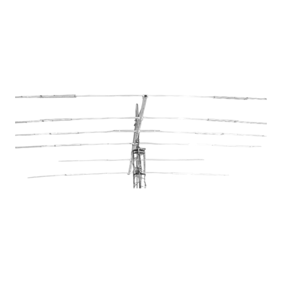
SPECIFICATIONS
MODEL NUMBER ................................................ KT36XA
FREQ. RANGE..................................................... 14.0 - 14.35 MHz
GAIN (Free Space) .............................................. SEE CHARTS
FRONT TO BACK ................................................ SEE CHARTS
FEED IMPEDANCE / CONNECTOR ................... 50 / SO-239
VSWR ................................................................... <1.5:1
POWER HANDLING ............................................ 3 kW
BOOM LENGTH / DIAMETER ............................. 32' / 3"
ELEMENT LENGTH ............................................. 25'
TURNING RADIUS .............................................. 21.5'
MAST SIZE .......................................................... 2" Nominal
WIND AREA ......................................................... 9.75 SQ. FT.
WIND SURVIVAL ................................................. 100 MPH
WEIGHT / SHIPPING WEIGHT ........................... 80 lb. / 85 lb. 2 boxes
FEATURES
2
The M
KT36XA is the result of many hours spent on perfecting the original KLM KT-34XA through computer
optimization confirmed by range and actual on-air tests. Five elements are active on 20 and 15 meters and all
six are working on 10 meters! This is the hottest performing tribander on the market! A dual driven element
(log cell) creates a rig pleasing, flat match, and broad gain & front to back curves across 10, 15, and 20m. A 3
kW 4:1 balun efficiently matches the antenna to 50. All hardware has been upgraded to our machined
shorting bars and rugged center element mounts. This is the strongest tribander on the market! We probably
could have called it the "KB36XA" cuz it does! ("KB" = Kicks Butt).
M2 Antenna Systems, Inc. 4402 N. Selland Ave. Fresno, CA 93722
Tel: (559) 432-8873 Fax: (559) 432-3059 Web: www.m2inc.com
M2 Antenna Systems, Inc.
Model No: KT36XA
21.0 - 21.45 MHz
28.0 - 29.0 MHz
©2015 M2 Antenna Systems Incorporated
10m
f, MHz G, dBi G, dbd
28.0
9.8
7.7
28.2
10.1
8.0
28.4
10.4
8.3
28.6
10.5
8.4
28.9
10.5
8.4
15m
f, MHz G, dBi G, dbd
21.0
9.2
7.1
21.1
9.3
7.2
21.2
9.4
7.3
21.3
9.5
7.4
21.4
9.6
7.5
20m
f, MHz G, dBi G,dbd
14.0
9.1
7.0
14.1
9.2
7.1
14.2
9.3
7.2
14.3
9.4
7.3
2/13/15
Rev.03
F/B
25
28
29
28
26
F/B
19
22
24
24
23
F/B
17
26
21
23
Advertisement

Related Manuals for M2 KT36XA


Summary of Contents for M2 KT36XA
-
Page 1: Specifications
FEATURES The M KT36XA is the result of many hours spent on perfecting the original KLM KT-34XA through computer optimization confirmed by range and actual on-air tests. Five elements are active on 20 and 15 meters and all six are working on 10 meters! This is the hottest performing tribander on the market! A dual driven element (log cell) creates a rig pleasing, flat match, and broad gain &... - Page 2 KT36XA ASSEMBLY MANUAL Tools: Phillips head screw driver, ‘green’, 11/32” nutdriver, 7/16” wrench, 7/16” socket, socket wrench, tape measure, and a friend. NOTE: To prevent galling of the stainless steel hardware, apply a light coating of Penetrox to all bolts and screws.
- Page 3 KT36XA ASSEMBLY MANUAL 3. CAPACITOR ASSEMBLIES ONTO LONGER 3/8” TUBES Locate the ten longer 3/8” diameter tubes. Upon inspecting the tubes, you’ll notice there are two holes drilled on one side only. The holes are to prevent moisture build up inside the capacitor tubes and to provide pressure equalization.
- Page 4 KT36XA ASSEMBLY MANUAL 4. GENERAL ASSEMBLY OF HALF ELEMENT SECTIONS We recommend assembling the half element sections on a clean, flat surface. There is an assembly drawing for each of the six elements with both the right and left halves shown on each page.
- Page 5 KT36XA ASSEMBLY MANUAL 5. HF CLAMP PLATE PAIR ASSEMBLY Locate the 11 element clamp plates, the Balun ‘L’-Bracket, 2-1/2” U-bolt & Saddle, and element clamp cap. Assemble the plates into six pairs with the radii facing each other using four 1/4-20 x 2” bolts. On one of the ‘alike’-pair combinations, attach the Balun ‘L’-Bracket to the outside clamp plate with the flat side up and higher...
- Page 6 KT36XA ASSEMBLY MANUAL 10. ELEMENT INSTALLATION We advise that you elevate the antenna boom onto a couple of sawhorses or bucks for the remaining assembly steps. Use the DIMENSION SHEET as a guide to properly install the six elements onto the boom. If you have not labeled which side of the element faces towards the front of the antenna, you will want to pay close attention to the DIMENSION SHEET.
- Page 7 KT36XA ASSEMBLY MANUAL 15. OVERHEAD GUY SUPPORT To prepare the overhead guy system, begin by temporarily installing a 2” U-bolt through the TURNBUCKLE PLATE and into the top set of 2” U-bolt holes on the boom to mast plate. Add a couple of 5/16” nuts to hold it in place.
- Page 8 KT36XA-HALF ELEMEN-GENERAL ASSEMBLY...
- Page 9 KT36XA ASSEMBLY MANUAL...
- Page 10 REAR DRIVEN ELEMENT DIMENSIONS...
- Page 11 FRONT DRIVEN ELEMENT DIMENSIONS...
- Page 12 1ST DIRECTOR ELEMENT DIMENSION...
- Page 13 2ND DIRECTOR ELEMENT DIMENSION...
- Page 14 3RD DIRECTOR ELEMENT DIMENSIONS...
- Page 15 DUAL DRIVEN AND T-MATCH ASSEMBLIES...
- Page 16 KT36XA DIMENSION SHEET...
- Page 17 KT36XA PARTS & HARDWARE DESCRIPTION ..............QTY Boom sections, 3" x .065” x 95” swaged ......4 Boom section, 3” x .065” x 28” straight ......... 1 Center sleeve, 7/8” x .058” x 36” STR ........3 Center Support Tube, 1” x .058” x 20” SBE ......1 Element, 1”...
- Page 18 KT36XA PARTS & HARDWARE IN BAG #6 Clamp Block, 3/8” ..............8 Phasing Line Insulator ............1 Turnbuckle plate, 1/8” x 2” x 5" ..........1 Balun ‘L’-Bracket, 1” x 1” x 4” ..........1 Balun Straps ................. 2 Fiberglass Insulator, 3/8” x 10” ..........1 Poly Disk Insulator, 7/8”...
- Page 19 BOX #1 PARTS & HARDWARE BOOM SEC. 3” W/ EYEBOLT HOLES ....2 1 X 72" SOE ............10 BUNDLE, 3/4 X 23" (6) & 3/4 X 21” (4) SOE ..1 BUNDLE, 3/4 X 12” SBE ........1 BUNDLE, ALL 1/2” TUBES ........1 TURNBUCKLE / EYEBOLT BAG ......
- Page 20 BOX #2 PARTS & HARDWARE BOOM SEC. 3” SOE, NO HOLES ......2 BOOM SEC. 3” X 28” STRAIGHT ......1 ODDBALL TUBE BUNDLE ........1 ELEMENT, 3/4 X 48” SOE ........2 CAPACITOR TUBE BUNDLE ........ 1 SHORT 3/8” TUBE BUNDLE ......... 1 MED.
Need help?
Do you have a question about the KT36XA and is the answer not in the manual?
Questions and answers