JCM Technologies KEEroll User Manual
Hide thumbs
Also See for KEEroll:
- User manual (20 pages) ,
- User manual (20 pages) ,
- User manual (28 pages)
Table of Contents
Advertisement
Quick Links
Advertisement
Table of Contents
Troubleshooting

Related Manuals for JCM Technologies KEEroll


Summary of Contents for JCM Technologies KEEroll
- Page 1 KEEroll User Manual...
-
Page 2: Table Of Contents
Table of contents Important safety instructions Safety instructions for installation Safety instructions for the use Use of the equipment Introduction KEEroll Indicators Actions RadioSens3 System Battery life RadioBand3 System KEEpad & KEEpush KEEpad KEEpush KEEalarm SESAME SESAME features KEEroll Installation... - Page 3 Batteries replacement Troubleshooting Technical Data RadioBand System Installation Connection Programming Maintenance Leds and beeps indication table Replacing the transmitter battery Technical data KEEpad & KEEpush Installation Programming KEEpad KEEpush Verification KEEpad KEEpush Maintenance Batteries replacement KEEpad Troubleshooting Technical Data KEEalarm Programming Installation Verification...
-
Page 4: Important Safety Instructions
Important safety instructions Safety instructions for installation Disconnect the power supply whenever you proceed to the installation, maintenance or repair of the equipment. •Before installing the panel, remove all unnecessary ropes or chains and disable any equipment such as locks that is not necessary for the automatic operation. -
Page 5: Safety Instructions For The Use
Safety instructions for the use •Do not allow children to play with the door controls. •Keep the remote controls out of the reach of children. •Watch the door movement and keep people away until the door is fully open or closed. •Precaution when operating the manual unlocking device, as the door may suddenly fall due to the bad condition of the springs or door unbalance. -
Page 6: Introduction
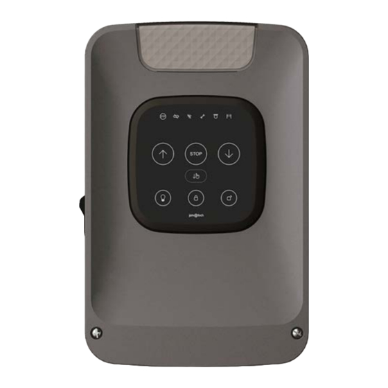
Introduction KEEroll Designed for residential aluminium roller shutters, the KEEroll solution has direct communication with the user and the installer. Its capacitive front with illuminated keys provides comfort and security. The door can be opened and closed by any person without the need for technical know-how. -
Page 7: Actions
Actions Press to open, stop and close the door. Press to close the door in dead man mode. Block transmitter function: KEEroll control panel incorporates a block button on the cover to prevent the door from being opened accidentally. Press to block the door, key lights on. -
Page 8: Radiosens3 System
RadioSens3 is an impact detection system installed at the last slat of the roller shutter. It detects the obstacle and reopens without causing any damage. The communication system between the RS3 T868 and the KEEroll is permanently monitored (two-way link via radio). Options and sensibility selectors must be set before programming. -
Page 9: Radioband3 System
RadioBand3 System The RadioBand system is designed of domestic, commercial and industrial door applications where a safety edge is used. The system provides a wireless system replacing spiral cables or energy chain systems to provide the safety signal to the door or gate control panel. -
Page 10: Keepad & Keepush
KEEpad & KEEpush KEEpad 3-channel motion transmitter; 3 different functions (open / close door, switch on courtesy light, activate KEEALARM...). Each of these channels is activated with a different password. KEEpush 3-channel motion transmitter; 3 different functions (open door, switch on courtesy light, ...) jcmtechnologies... -
Page 11: Keealarm
KEEalarm KEEalarm monitors your door and prevents a thief from quietly forcing your garage door. KEEalarm is an accessory that monitors for intrusions. If a thief tries to open your door by force, an acoustic alarm will be triggered. SESAME SESAME is the device for controlling the residential door with the mobile phone. -
Page 12: Keeroll
KEEroll Installation Control panel fixations Remove the front cover of the control panel. Install the bottom part on the wall in a vertical position, at least 1,5 meters over the ground and in accordance with the assembly instructions below. jcmtechnologies... -
Page 13: Connections
Connections To prevent electric shocks, the equipment must be disconnected from the power supply and all the electrical connections. 230VAC MONOPHASE MOTOR OUTPUTS jcmtechnologies... - Page 14 OPTO SAFETY EDGE / 8k2 SAFETY EDGE INPUT (AUTOEDGE) PHOTOCELL INPUT PUSHBUTTONS INPUTS jcmtechnologies...
-
Page 15: Configuration / Starting Up
Configuration / Starting up Connect the power supply Adjusting limit switch Door MUST BE AT HALFWAY position before starting the limit switch adjusting Dipswitch 1 in ON. Door will move in dead man mode. Keep pressed to move up or down the door. Press , to change the phase of the motor in case the door is not moving in the proper sense. -
Page 16: Set Courtesy Light
Set courtesy light It is possible to define the activation time of the courtesy light. To change the setting hold and release. Repeat this step until the desired setting is reached (see table). You can only access settings with the door closed and the DIP 1 selector OFF. Frontal light Activation time 1 flash... -
Page 17: Manoeuvre Programming
First program the safety elements (RadioSens3 or RadioBand3). Then program the maneuver. Door MUST BE TOTALLY CLOSED before starting the manoeuvre programming. Enter Installer mode: Press (KEEroll programming button), the maintenance indicator lights on, a beep will be heard. Autoclose time. -
Page 18: Verification
Verification Verify that the control panel is working properly Once the control panel is correctly wired and programmed, check that all the system (accessories included) is working prop- erly. Transmitter Press the transmitter button and check that the door opens. Press again, and check that the door stops/closes. Photocell Check that the LED is at OFF. -
Page 19: Maintenance
Maintenance Enter Installer mode: Press (KEEroll programming button), the maintenance indicator lights on, a beep will be heard. The following functions can be done inside this maintenance mode. Program maintenance manoeuvres Maintenance warning: By entering Installer mode you can set the number of manoeuvres for the maintenance warning. -
Page 20: Reset Safety Elements
Reset safety elements Hold until keys starts flashing, Without releasing and press , to erase safety a beep will be heard. elements, some beeps will be heard followed by a long beep. In case of erasing safety elements, the manoeuvre has to be reprogrammed again. -
Page 21: Troubleshooting
Troubleshooting INDICATOR SOLUTION Emergency stop input activated Low battery detection Verify the batteries of the safety transmitter Verify the radio signal. Check the batteries, Radio communication error reprogram again or change equipments loc- ation. ON: Installer mode See Maintenance chapter Flashing: Maintenance warning ON: Closing photocell activation error Flashing: Indicates the reversed movement... -
Page 22: Radiosens3 System
RadioSens3 System Installation Install the transmitter following the steps and recommendations below. Pass the cables through the holes indicated (only if you use the lock connection). Install the transmitter in a horizontal position, at the middle of the last slat (it must have a tolerance of minimum 2mm of movement). -
Page 23: Impact Detection Adjustment
(not the manoeuvre). Programming Enter Installer mode: Hold (KEEroll programming button), the maintenance indicator lights on, a beep will be heard. Press the PROG button of RadioSens3 transmitter, a beep will be heard once it is programmed. -
Page 24: Troubleshooting
Troubleshooting green D1 red led Message / issue Solution Flash at beginning Control panel asks RS3 correct signal of opening transmitter to start the manoeuvre Flash at beginning Indicates calibration failure of RS3 Reprogram the manoeuvre until no of closing transmitter in open door status calibration failure Indicates that the door is passing... -
Page 25: Radioband System
RadioBand System Installation Connection IN1 Connection SW1:1 SW1:2 JCM Optical safety edge (OSE-S7502B and OSE-S7502) Standard optical safety edge 8k2 resistive safety edge NC contact* IN2 Connection SW1:3 NC contact* 8k2 resistive safety edge * In order to comply with the EN 12453:2017 safety standard, NC contact input can not be used to connect safety devices. - Page 26 8k2 RESISTIVE SAFETYEDGE / MECHANICAL OR CONTACT DEVICES OSE-S7502 “ALWAYS ON” OPTICAL SAFETYEDGE jcmtechnologies...
- Page 27 STANDARD OPTICAL SAFETYEDGE (Only used with ATEST function) OSE-S7502B “ALWAYS ON” OPTICAL SAFETYEDGE OSE-S7502B “ALWAYS ON” OPTICAL SAFETYEDGE AND WICKET DOOR CONTACT jcmtechnologies...
-
Page 28: Programming
Programming Enter Installer mode: Hold (KEEroll programming button), the maintenance indicator lights on, a beep will be heard. Press the PROG button of RadioBand3 transmitter, a beep will be heard once it is programmed. Press again to exit Installer mode, lights offand two beeps will be heard. -
Page 29: Maintenance
Maintenance Leds and beeps indication table The status of leds is shown during 5 minutes after pressing PROG button or during the Check function. The rest of the time they are turned off. IN1/IN2 Beeps Equipment Message Solution No beeps Safety edge activated transmitter Safety edge connection and... -
Page 30: Technical Data
Technical data Parameter Value Frequency Multifrequency system 868 MHz auto-adjustable Operating consumption 12mA Radiated power < 25mW Minimum / Maximum range (in open 0,20m / 50m field) 1,5 Years (standard use with optical safety edge: 4 manoeuvres of Battery life (aprox) 30s a day) Reaction time (typical) 35ms... -
Page 31: Keepad & Keepush
KEEpad & KEEpush Installation Remove plastic from batteries Save master code label in a safe place Screw back cover (KEEpad) Fix support Slide on wall support Fix device (use provided tool) Do not install near transmitting equipment of radiofrequency (it could decrease the battery life time). jcmtechnologies... -
Page 32: Programming
Programming Press the key (you hear a beep and the key lights on) until you reach the necessary channel settings (see "Transmitter programming" table for the different settings). You can only access settings with the door closed and the DIP 1 selector OFF. KEEpad Wake up Enter the channel password to be programmed + OK... -
Page 33: Verification
Verification KEEpad Enter the password and check that the door opens. Enter the password again, and check that the door stops/closes. Wake up Enter the password + OK The anti-spy feature allows you to press random numbers before entering the password (the KEEpad only uses the last digits). -
Page 34: Maintenance
Maintenance Batteries replacement Unscrew device and slide on wall Unscrew back cover Replace batteries (3 x 1,5Vdc AAA support type) When batteries are near to the end of its useful life time, the indicator flashes. KEEpad Configure password Wake up Enter configuration mode Choose channel (1/2/3) Enter current password (4-8 digits) - Page 35 Reset Enter master code (see yellow label) + Enter configuration mode Select reset After a correct reset the default passwords are restored and, for safety, the keypad is reset from the receiver (it must be programmed again). jcmtechnologies...
-
Page 36: Troubleshooting
Troubleshooting Issue Solution The device has the batteries inserted but it does not Check if there is the factory plastic in the battery wake up. holder or if the batteries are empty. The device wakes up but can not be programmed to Check the distributor code and installer code from the receiver. -
Page 37: Technical Data
Technical Data Parameter Value Operating frequencies 868,35 MHz Coding High security changing code Number of channels Power supply 3 batteriesAAA 1,5V Radiated power <1mW Operating consumption 12mA Watertighness IP65 Operating temperature -20ºC to +55ºC Autonomy 2 years (aprox) jcmtechnologies... -
Page 38: Keealarm
KEEalarm Programming The KEEroll dipswitch 4 in ON position. Press the key (you hear a beep and the key lights on) until you reach the necessary channel settings (see "Transmitter programming" table for the different settings). You can only access settings with the door closed and the DIP 1 selector OFF. -
Page 39: Installation
Installation Verification Make sure that the LEDs are OFF If it is activated when the door's moving, the LEDs will remain at OFF, indicating the activation of the KEEalarm. Maintenance When the alarm is activated: Deactivate the alarm Press any button on a programmed transmitter. Rearm the alarm Open the door fully and then close it. -
Page 40: Sesame
SESAME Connections Connect the SESAME device to your KEEroll control panel (use the RJ-45 connector). The LED status should be flashing green and the LED network should be flashing red, which shows that the device needs to be configured. Make sure your control panel has this symbol on it's label, otherwise it won't work with Sesame. -
Page 41: Configure Sesame In "Honoa
Configure SESAME in "Honoa" Once WiFi is set up, it is possible to add the device in JCM Technologies, S.A.'s mobile application "Honoa." If you do not have "Honoa" on your mobile, download the application. You must login to enter the app. If you do not have an account, please register. - Page 42 Licenses Once the device has been added to the "Honoa" application, you must enter a license to be able to use it. 2 licenses are inside the box. If you need more licenses, please contact your distributor. jcmtechnologies...
- Page 43 Press on "GARAGE HOUSE" (Place) and, on the SESAME device, on "LICENSE." Scan the license's QR code or manually input the code. Press "SAVE." jcmtechnologies...
-
Page 44: Verification
Verification Maintenance Resetting the device Reset the device if changing the Wi-Fi network or your Wi-Fi password. To reset SESAME, press the WPS/ RESET button for 10 seconds, with the device connected. The LED “Status” will be set to green, and “Network" and "Internet" to flashing red. Stop pressing the button when "Internet"... -
Page 45: Led Behaviour
LED behaviour FIXED BLINKING State Status LED Network LED Internet LED Action Power off Starting WAIT Use embedded web or WPS to Wi-Fi Configuring configure connectivity Wi-Fi Configuring timeout REBOOT DEVICE Connecting Wi-Fi WAIT WRONG WI-FI PASSWORD Wi-Fi Error CHECK ROUTER (WI-FI) Internet Connecting WAIT CHECK ROUTER (INTERNET) -
Page 46: Notes
Notes jcmtechnologies... - Page 47 Notes jcmtechnologies...
-
Page 48: Regulatory Data Eu Declaration Of Conformity
Regulatory Data EU Declaration of conformity JCM TECHNOLOGIES, S.A. hereby declares that the product KEEROLL complies with the relevant fundamental require- ments of the RED Directive 2014/53/EU, as well as with the Machine Directive 2006/42/EC whenever its usage is foreseen;...
Need help?
Do you have a question about the KEEroll and is the answer not in the manual?
Questions and answers
I **** getting 4 beeps from my garage door controller. The manual suggests… Remove the box cover. Replace the two used batteries with new ones, taking into account the polarity indicated by the ****-nector. Check that the new batteries support the same temperature range as those they are replacing. I have removed the cover and cannot see the batteries. Please advise.
To locate and replace the batteries in the JCM Technologies KEEroll garage door controller:
1. Check Battery Status: If the LED is ON, the RadioSens3 connected is in a low battery state.
2. Remove the Bottom Part: Detach the bottom section of the controller.
3. Replace Batteries: Insert two new 1.5V DC LR6 AA batteries, ensuring correct polarity.
4. Check Temperature Range: Ensure the new batteries support the same temperature range as the old ones.
5. Do Not Mix Batteries: Avoid using old and new batteries together.
6. Reattach the Bottom Part: Secure it back in place.
7. Dispose of Old Batteries Properly: Remove them from the device and deposit them in a collection point.
Battery duration is approximately 2 years.
This answer is automatically generated