
Related Manuals for ADLINK Technology DMI-1040

Summary of Contents for ADLINK Technology DMI-1040
- Page 1 DMI-1040 10.4" Driver Machine Interface User’s Manual Manual Rev.: Revision Date: April 15, 2021 Part No: 50M-00018-1000...
- Page 2 Revision History Revision Release Date Description of Change(s) 2021-04-15 Initial release Revision History...
-
Page 3: Preface
DMI-1040 Preface Copyright © 2021 ADLINK Technology Inc. This document contains proprietary information protected by copy- right. All rights are reserved. No part of this manual may be repro- duced by any mechanical, electronic, or other means in any form without prior written permission of the manufacturer. - Page 4 California Proposition 65 Warning WARNING: This product can expose you to chemicals including acrylamide, arsenic, benzene, cadmium, Tris(1,3-dichloro-2-propyl)phosphate (TDCPP), 1,4-Diox- ane, formaldehyde, lead, DEHP, styrene, DINP, BBP, PVC, and vinyl materials, which are known to the State of California to cause cancer, and acrylamide, benzene, cadmium, lead, mercury, phthalates, toluene, DEHP, DIDP, DnHP, DBP, BBP, PVC, and vinyl materials, which are known to the State of California to cause...
-
Page 5: Table Of Contents
List of Tables................xi 1 Introduction ................ 1 Overview................1 Features................1 Package Contents ............... 2 2 System Description............3 DMI-1040 Specifications............3 Block Diagram ..............5 Mechanical Layout............... 6 Mechanical Dimensions............8 Power Specifications ............9 2.5.1 Power Consumption............9 2.5.2 System Power Features.......... - Page 6 Windows ................29 Linux Drivers ..............39 4.2.1 GPS................39 4.2.2 Cold & Warm Boot Test ..........40 4.2.3 CAN Bus ..............40 4.2.4 Multifunction Vehicle Bus (MVB ) ......... 41 4.2.5 Touch Panel ..............50 4.2.6 Ambient Light Sensor ........... 50 4.2.7 Wi-Fi and Bluetooth............
- Page 7 DMI-1040 7.4.6 Thermal Management ..........78 7.4.7 Watchdog Timer............79 7.4.8 Super IO Configuration ..........79 7.4.9 Serial Port x Configuration ........... 80 7.4.10 Serial Console Redirection ........... 80 7.4.11 Network Stack Configuration........83 7.4.12 Trusted Computing............83 7.4.13 USB Configuration ............83 7.4.14 Intel I210 Gigabit Network Connection......
- Page 8 This page intentionally left blank. viii Table of Contents...
-
Page 9: List Of Figures
List of Figures Figure 2-1: DMI-1040 Block Diagram..........5 Figure 2-2: DMI-1040 Front Layout............ 6 Figure 2-3: DMI-1040 Rear, Side and Bottom I/O Layout ....7 Figure 2-4: DMI-1040 Dimensions ............. 8 Figure 3-1: DMI-1040 Mounting Hole Locations ......23 Figure 3-2: Mounting the DMI-1040 .......... - Page 10 This page intentionally left blank. List of Figures...
-
Page 11: List Of Tables
DMI-1040 List of Tables Table 2-1: DMI-1040 Specifications..........3 Table 6-1: Status LED Definitions........... 59 Table 6-2: COM RS-232 DB9 Pinout (male)........60 Table 6-3: COM RS-422 DB9 Pinout (female)........ 61 Table 6-4: USB 2.0 M8 Connector Pinout........61 Table 6-5: GbE1/GbE2/GbE3 M12 Connector Pinout .... - Page 12 This page intentionally left blank. List of Tables...
-
Page 13: Introduction
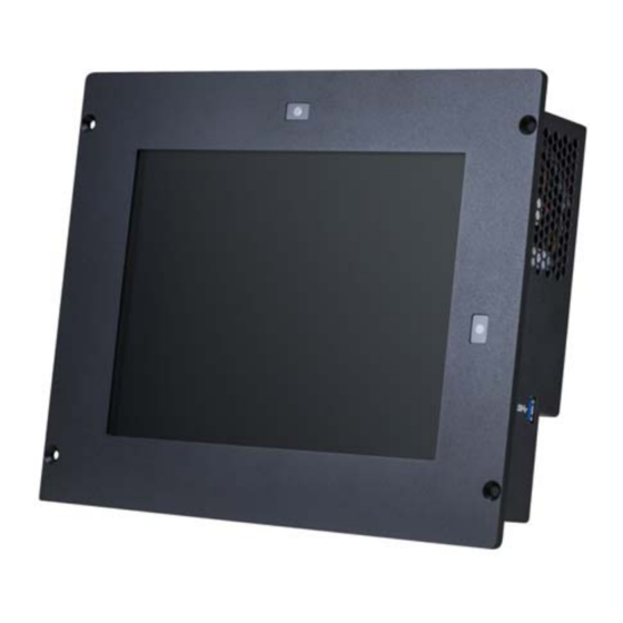
DMI-1040 Introduction 1.1 Overview The DMI-1040 is a 10.4" Driver Machine Interface panel PC designed specifically for the railway industry, equipped with Intel Atom® x5-E3930 processor (formerly Apollo Lake), resistive touch, and EN50155 compliance power module. It can be applied as an HMI unit for driver’s desks, control panel for passenger infor-... -
Page 14: Package Contents
1.3 Package Contents Please check that your package contains the items below. If you discover damaged or missing items, please contact your vendor. DMI-1040 Driver Machine Interface Panel PC (features dependent on specific model ordered) Mounting Screw Kit Optional Accessories... -
Page 15: System Description
1x Full-size Mini PCIe slots Expansion 2x SIM card slots Antennas Light Sensor Sensor on front bezel to detect ambient illuminance Speakers 2x speakers on rear panel Status LEDs Power 1x power status LED Table 2-1: DMI-1040 Specifications System Description... - Page 16 4572 m (15000 ft) at 25°C (MIL-STD-810G Method 500.5, Altitude Procedure II2) Software BIOS AMI BIOS Board ADLINK SEMA 3.5 for WDT, hardware monitor, and fail-safe dual Management BIOS Operating Linux Ubuntu 16.04 LTS, 64-bit System Windows 10 64-bit Table 2-1: DMI-1040 Specifications System Description...
-
Page 17: Block Diagram
Conn x1 DDR3L RS232 Socket Port x1 RS232 DB9x2 RS-232 (Male) Module (opt.) RS422 USB 3.0 Port x1 Type A x1 5-wire LVDS & Light Back Light Sensor Touch Panel 10.4" LCD Module Figure 2-1: DMI-1040 Block Diagram System Description... -
Page 18: Mechanical Layout
2.3 Mechanical Layout Front View Ambient Brightness Sensor Power Status Figure 2-2: DMI-1040 Front Layout System Description... -
Page 19: Figure 2-3: Dmi-1040 Rear, Side And Bottom I/O Layout
Rear, Side and Bottom Views 2x RS-232 w/ 2.5kVDC isolation (optional) RS-422 DC Input 2x Speakers (female) GbE 2 USB 2.0 RS-232 Ground USB 3.0 GbE 3 (male) Stud GbE 1 CFast Slot Figure 2-3: DMI-1040 Rear, Side and Bottom I/O Layout System Description... -
Page 20: Mechanical Dimensions
2.4 Mechanical Dimensions 215.40 Bezel 58.90 Dimensions in mm Figure 2-4: DMI-1040 Dimensions System Description... -
Page 21: Power Specifications
DMI-1040 2.5 Power Specifications 2.5.1 Power Consumption The following table shows the DMI-1040 power consumption data at room temperature. Input Power Loading Setup Voltage Current Voltage Cons. Linux max mode/ Stress 23.996V 1.5144A 36.339W Enable EIST Linux typical mode/ Stress 23.996V... -
Page 22: System Power Features
2.5.2 System Power Features Operating Voltage Range The system is equipped with a wide DC input range from 16.8V to 137.5V. Input range: 16.8V to 137.5V Max. input current: 0.35A by 137.5V Input Over-Voltage Protection When the input voltage exceeds the 160V, the module will shut down, and try to restart every 6 seconds until the over current con- dition is corrected. -
Page 23: Getting Started
DMI-1040 Getting Started 3.1 Removing the Rear Cover To install the optional modules, first remove the rear cover as described below. 1. Remove the cover on the USB 3.0 slot as shown. USB Cover Getting Started... - Page 24 2. Remove all the screws indicated (14 screws around the edge, 9 screws on the I/O panel, 3 screws on the cover). Do NOT remove the unmarked screws on the back cover. They are used to secure the heat spreaders inside the cover. NOTE: NOTE: Getting Started...
- Page 25 DMI-1040 3. When reinstalling the cover, gradually tighten the screws in the order shown in the diagram below to a torque of 3.5 kgf-cm (first blue, then red, then magenta). 4. Replace the cover on the USB 3.0 slot removed in Step 1 above.
- Page 26 5. Remove the rear cover. It may be necessary to use a tool such as a flat-head screwdriver to lift the cover away from the display frame. Getting Started...
- Page 27 DMI-1040 6. Disconnect the cable connecting the speakers to the main board. Getting Started...
-
Page 28: Installing A Mini Pcie Mvb Module (Optional)
3.2 Installing a Mini PCIe MVB Module (optional) Follow the instructions below to install a Mini PCIe MVB module. 1. Remove the cover on the D-SUB port openings. Getting Started... - Page 29 DMI-1040 2. Install the Mini PCIe MVB module and secure it with two screws as shown. Getting Started...
- Page 30 3. Secure the two D-SUB cables to the D-SUB port openings on the rear cover with screws as shown. Getting Started...
- Page 31 DMI-1040 4. Place the rear cover over the device as shown and con- nect the D-SUB cables to the Mini PCIe MVB module. 5. Reconnect the cable connecting the speakers to the main board, reinstall the rear cover onto the device, and secure the cover by replacing the screws.
-
Page 32: Installing Other Mini Pcie Modules (Optional)
3.3 Installing other Mini PCIe Modules (optional) For instructions on installing other types of Mini PCIe modules, please contact ADLINK at http://askanexpert.adlinktech.com. Getting Started... -
Page 33: Cfast Card Installation
DMI-1040 3.4 CFast Card Installation To install or remove the CFast card, remove the screws securing the CFast slot cover and remove the cover. Insert the CFast card and secure the cover. Getting Started... -
Page 34: Mounting
3.5 Mounting The DMI-1040 can be panel mounted using 4 countersunk M5 screws and O-rings. Make sure there is adequate space behind the panel for ventilation and I/O connectors, and that the panel material and thickness can support the weight of the device. -
Page 35: Figure 3-1: Dmi-1040 Mounting Hole Locations
DMI-1040 M5 THREAD*4 5.5*4 for APPLYING M5 NUT 7.50 +0.50 Figure 3-1: DMI-1040 Mounting Hole Locations Getting Started... -
Page 36: Figure 3-2: Mounting The Dmi-1040
M5 Nut (for 5.5 through hole) Platform DMI-1040 O-Ring M5xL40 Screw (torque: 10.0 Kgf-cm) Figure 3-2: Mounting the DMI-1040 Getting Started... -
Page 37: Connections
DMI-1040 3.6 Connections Connecting a Ground Cable Connect the ground cable before making any other connec- tions. When disassembling the system, always detach the ground cable last. CAUTION: Use a ground cable with a cross section of at least 0.823mm (18AWG) and an M4 size ring terminal. - Page 38 Connecting the Power Supply Work on the computer system may only be carried out by personnel qualified for the specific task and who have the training and experience to identify risks and WARNING: avoid potential hazards. Make sure that a ground cable has been connected to the system before connecting an external power supply and switching on the system.
-
Page 39: Starting Up The System
The first boot device is the onboard eMMC. To enter the BIOS setup menu to change the boot device order, enter Del or Esc. The DMI-1040 can be delivered with Linux Ubuntu 16.04 LTS 64-bit or Windows 10 64-bit already installed, or without any oper- ating system. - Page 40 This page intentionally left blank. Getting Started...
-
Page 41: Driver Installation
4.1 Windows Please download the Windows drivers from the ADLINK website at www.adlinktech.com. The following describes the DMI-1040 driver installation proce- dures for Windows 10. Install the Windows operating system before installing any driver. Most standard I/O device drivers are installed during Windows installation. - Page 42 12.Wi-Fi: To install the Wi-Fi driver, download the driver package ...\ENLI_Ampak_AP12356_Windows 10 and do the following. Open the Device Manager, R-click on Other Devices > Unknown Device and select Update Driver. Driver Installation...
- Page 43 DMI-1040 Select Browse my computer for driver softwaret Under “Search for drivers in this location”, click the Browse button. Driver Installation...
- Page 44 Navigate to the folder where you saved the driver package, go to the path for your OS, then click OK Windows 10 (x64): ...\ENLI_Ampak_AP12356_Windows 10 \Win_10_32_64bit\ WiFi\x64\DHD_1.558.53.33_Win10_x64_HLK_driveronly Windows 10 (x86): ...\ENLI_Ampak_AP12356_Windows 10 \Win_10_32_64bit\WiFi\x86\DHD_1.558.53.33_Win10_x86 _HLK_driveronly Driver Installation...
- Page 45 DMI-1040 Click Next. The system will begin installing the Wi-Fi driver. Driver Installation...
- Page 46 After the driver has finished installation, click Close. (Note: the AP12356 module is equipped with a Broadcom chip and has the device name Broadcom 802.11ac Wireless PCEI Full Don- gle Adapter.) Driver Installation...
- Page 47 DMI-1040 Navigate to the path ...\ENLI_Ampak_AP12356_Windows 10\ Win_10_32_64bit. Right click on the file Install_nvram.bat and click Run as Administrator. Driver Installation...
- Page 48 Click Yes in the User Account Control pop-up. This will copy the file 4356r2nvram.txt into C:\Windows\System32\drivers. Driver Installation...
- Page 49 DMI-1040 Open the Device Manager, R-click on Broadcom 802.11ac Wireless PCEI Full Dongle Adapter and disable it Click Yes when asked to confirm. Driver Installation...
- Page 50 R-click on Broadcom 802.11ac Wireless PCEI Full Dongle Adapter and enable it. Restart the system to complete Wi-Fi module installation. Driver Installation...
-
Page 51: Linux Drivers
DMI-1040 4.2 Linux Drivers To install the Linux drivers, please download drivers from the ADLINK website at www.adlinktech.com and follow the instruc- tions below. 4.2.1 By default, GPS uses the legacy UART driver, and its interface is "/dev/ttyS2" (dependent on BIOS settings), baud rate 115200. -
Page 52: Cold & Warm Boot Test
4.2.2 Cold & Warm Boot Test //Cold Boot Test #cd ~/Desptop/DMI-1210/applications/GPS/ #chmod +x *.sh #./gps_logger.sh cold /dev/ttyS2 //Warm Boot Test #./gps_logger.sh warm /dev/ttyS2 4.2.3 CAN Bus To install the vendor provided SDK package (v2.1.8), first make sure the cp210x.c driver is enabled on your platform. It will export two interfaces under /dev/. -
Page 53: Multifunction Vehicle Bus (Mvb )
DMI-1040 4.2.4 Multifunction Vehicle Bus (MVB ) Duagon D017M Enable the drivers. // build driver and loading # cd $MVB_SDK/Mini_PCIe/linux/x86_linux/io/src/ # make && make load # lspci –k // check driver loaded # cd $MVB_SDK/Mini_PCIe/linux/x86_linux/devel //compiler library file libhost.a # make //copy libhost to $MVB_SDK/Mini_PCIe/linux/x86_linux/api/lib/ # cp –rf lib* ../api/lib/... - Page 54 // test by tcn_md_demo (Message Data) # cd $MVB_SDK/Mini_PCIe/linux/x86_linux/app/tcn_md_demo # make # ./tcn_md_demo –t 0 root@adlink-SP-AL:/home/adlink/DMI-1210/sdk/MVB/d-010907-019128_encrypt/d-010907 -019128/x86_linux/app/tcn_md_demo# ./tcn_mvb_md_demo -t 0 CARD 0 - CARD 0 -Demo of TCN MD Driver API CARD 0 -====================== CARD 0 -- as_init() 0x00000000: 0x00 0x00000008: 0x00 0x00000010: 0x00 0x00000001: 0x00 0x00000009: 0x00 0x00000011: 0x00 0x00000002: 0x00 0x0000000A: 0x00 0x00000012: 0x00 0x00000003: 0x00 0x0000000B: 0xFF 0x00000013: 0xFF...
- Page 55 DMI-1040 CARD 0 -************************************************* CARD 0 -* TCN MVB MD demo application Loop * CARD 0 -************************************************* CARD 0 -am_receive_request() CARD 0 -- replier_function=200 CARD 0 -- in_msg_size =200 CARD 0 -- replier_ref =0x0061320C CARD 0 -am_call_request() CARD 0 -- caller_function =100 CARD 0 -- out_msg_adr ="duagon is cool!"...
- Page 56 Duagon D113 SERVER mode preferred option set combinations are as fol- lows (source: Duogon D113 Datasheet.). SERVER Preferred Option Set Combinations The functionality as described (no customer specific changes) can be identified with the following document numbers: Intended Document number downloadable options Description hardware...
- Page 57 DMI-1040 Please use the package "d-013928-039917" to enable the D013 PC-104 module. // build libraries # cd d-013928-039917/linux/devel # make && make copy //test PD with its sample app # cd d-013928-039917/linux/app/tcn_pd_demo # make # ./tcn_pd_demo -t 0 // get the following result root@adlink-SP-AL:~/d-013928-039917/linux/app/tcn_pd_demo# ./tcn_pd_demo -t 0...
- Page 58 - ap_get_dataset(0x018) -> result -> port_data = 0x00 0x00 - ap_put_dataset(0x018) -> port_data = 0x12 0x34 - ap_get_dataset(0x010) -> result -> port_data = 0x00 0x00 - ap_get_dataset(0x018) -> result -> port_data = 0x12 0x34 - ap_put_dataset(0x018) -> port_data = 0x12 0x34 - ap_get_dataset(0x010) ->...
- Page 59 DMI-1040 - ap_get_dataset(0x018) -> result -> port_data = 0x12 0x34 - ap_put_dataset(0x018) -> port_data = 0x12 0x34 - ap_get_dataset(0x010) -> result -> port_data = 0x00 0x00 - ap_get_dataset(0x018) -> result -> port_data = 0x12 0x34 - ap_put_dataset(0x018) -> port_data = 0x12 0x34 - ap_get_dataset(0x010) ->...
- Page 60 ************************************************* * TCN demo application terminates successfully! * ************************************************* ************************************************* * Test of TCN Driver API 0 terminates successfully!* ************************************************* //test MD with its sample app # cd d-013928-039917/linux/app/tcn_md_demo # make # ./tcn_md_demo -t 0 root@adlink-SP-AL:/home/adlink/DMI-1210/sdk/MVB/d-010907-019128_encrypt/d-010907 -019128/x86_linux/app/tcn_md_demo# ./tcn_mvb_md_demo -t 0 CARD 0 - CARD 0 -Demo of TCN MD Driver API CARD 0 -======================...
- Page 61 DMI-1040 CARD 0 -************************************************* CARD 0 -* TCN MVB MD demo application Loop * CARD 0 -************************************************* CARD 0 -am_receive_request() CARD 0 -- replier_function=200 CARD 0 -- in_msg_size =200 CARD 0 -- replier_ref =0x0061320C CARD 0 -am_call_request() CARD 0 -- caller_function =100 CARD 0 -- out_msg_adr ="duagon is cool!"...
-
Page 62: Touch Panel
4.2.5 Touch Panel The touch panel driver is built-in by default. A resistance touch panel calibration tool is provided. // install PenMount calibration tool # cd $PENMOUNT/pmLinux-Debian8/ // at this step, it will take a while, please patient # ./install.sh // after finished installation, please reboot system # reboot 4.2.6... - Page 63 DMI-1040 [DBG] :read data failure [DBG] :seeking /dev/i2c-5 [DBG] :write data 0x00 fail [DBG] :read data failure [DBG] :seeking /dev/i2c-6 [DBG] :write data 0x00 fail [DBG] :read data failure [DBG] :seeking /dev/i2c-7 [DBG] :write data 0x00 fail [DBG] :read data failure...
-
Page 64: Wi-Fi And Bluetooth
4.2.7 Wi-Fi and Bluetooth Wi-Fi and Bluetooth functionality are suppported by the Mini PCIe AP12356 module. Wi-Fi Function Install //install Wifi module $sudo su #./install.sh Bluetooth Function Install If your kernel is default version (linux-4.13.0-43.generic), you can run install_bt.sh to install the Bluetooth module directly. //install Bluetooth module $sudo su #./install_bt.sh... -
Page 65: Usb Wakeup Function (Optional)
DMI-1040 4.2.8 USB Wakeup Function (optional) For customers who need the mouse and touch screen to wake up from S3, S4 and S5, the software BSP provides a driver (usbhid) patch for this function. Download the kernel source as shown below. - Page 66 This page intentionally left blank. Driver Installation...
-
Page 67: Display Utilities
DMI-1040 Display Utilities 5.1 Calibrating the Touch Panel - Ubuntu Download the PenMount touchscreen calibration tool Pen- Mount-Ubuntu 12.04-18.04 32_64bit Driver from the manufac- turer’s website by using the following search. http://www.amtouch.com.tw/downloads/penmount-drivers/ Uncompress the package and install it by doing the following: // Uncompress PenMount calibration tool # tar –jxvf pmLinux-Ubuntu_12.04-18.04_32_64bit_Driver_V4.5.6.tar.bz2... - Page 68 To calibrate the touchscreen, perform the following steps. 1. Select “Filter” and search for "Pen" to find the PenMount Utility. 2. Open the utility, select the number of points you wish to calibrate and click on “Calibrate” to start. 3. Press the red dot to start the calibration process. Display Utilities...
-
Page 69: Reading The Ambient Light Sensor
DMI-1040 5.2 Reading the Ambient Light Sensor The DMI-1040 is equipped with an Everlight DCDIC-17 ambient light sensor. Below is a sample application to read out the ADC values and calculate the illuminance in lux. // visit folder to compile application # cd $APP_ALS/ # gcc als_read.c -o als_read... -
Page 70: Display Brightness Control
5.3 Display Brightness Control The LCD backlight can be controlled using the following com- mand: echo $1> /sys/devices/pci0000\:00/0000\:00\:02.0/drm/ card0/card0-eDP-1/intel_backlight/brightness $1= 0~96000 (0=dark, 96000= max. brightness) #Set brightness to min echo 0>/sys/devices/pci0000:00/0000:00:02.0/drm/ card0/card0-eDP-1/intel_backlight/brightnes #Set brightness to max echo 96000>/sys/devices/pci0000:00/0000:00:02.0/drm /card0/card0-eDP-1/intel_backlight/brightness Users can build into their own application to enable auto dimming by reading the ambient light sensor and setting the LCD backlight brightness accordingly. -
Page 71: Interfaces
DMI-1040 Interfaces 6.1 Status LEDs Please refer to Figure 2-2 DMI-1040 Front Layout on page 6 for status LED locations. Function LED is on when DC Power is connected and system is Power Status powered on Table 6-1: Status LED Definitions... -
Page 72: Pin Definitions
6.2 Pin Definitions Please refer to Figure 2-3 DMI-1040 Rear, Side and Bottom I/O Layout on page 7 for connector locations. COM RS-232 DB9 Connector (male) Pin 1 Pin 5 Pin 6 Pin 9 Pin # RS-232 (male) COM3_RX_Console_R COM1_RXD_CN_R... -
Page 73: Table 6-3: Com Rs-422 Db9 Pinout (Female)
DMI-1040 COM RS-422 DB9 Connector (female) Pin 1 Pin 5 Pin 9 Pin 6 Pin # RS-422 (female) CH_COM_GND COM2_TXD_CN COM2_RXD_CN GND_COM_ISO COM2_DTR-L_CN COM2_DCD-L_CN Table 6-3: COM RS-422 DB9 Pinout (female) USB 2.0 M8 Connector Pin # Signal Name USB_P2_CN USB_P2_CP Table 6-4: USB 2.0 M8 Connector Pinout... -
Page 74: Table 6-5: Gbe1/Gbe2/Gbe3 M12 Connector Pinout
GbE1/GbE2/GbE3 M12 Connectors Pin # Signal Name MDO0P MDO0N MDO1P MDO1N MDO3P MDO3N MDO2N MDO2P Table 6-5: GbE1/GbE2/GbE3 M12 Connector Pinout DC Power Input Connector Pin # Signal V(+) V(-) 4-12 Table 6-6: DC Power Input Pinout Interfaces... -
Page 75: Table 6-7: Usb2 (Usb 3.0) Pinout
DMI-1040 USB2 Connector (USB 3.0) Pin # Signal Name USB2_P0_DN USB2_P0_DP USB3_P0_RXN USB3_P0_RXP USB3_P0_TXN USB3_P0_TXP Table 6-7: USB2 (USB 3.0) Pinout Interfaces... -
Page 76: Table 6-8: Cfast Socket Pin Definition
CFast Socket Pin # Signal Name Ground SATA_TX-P SATA_TX-N Ground SATA_RX-N SATA_RX-P Ground CFast_CDI Ground Ground CFast_LED1 CFast_LED2 P3V3 P3V3 Ground Ground CFast_CDO Table 6-8: CFast Socket Pin Definition Interfaces... -
Page 77: Bios
DMI-1040 BIOS 7.1 Introduction The following chapter describes basic navigation for the AMI EFI BIOS setup utility. 7.2 Entering BIOS Setup To enter the setup screen, follow these steps: 1. Power on the motherboard 2. Press the < Delete > key on your keyboard when you see the following text prompt: <... - Page 78 Navigation The BIOS setup/utility uses a key-based navigation system called hot keys. Most of the BIOS setup utility hot keys can be used at any time during the setup navigation process. There is a hot key legend located in the right frame on most setup screens.
- Page 79 DMI-1040 Hotkey Descriptions Enter The < Enter > key allows you to display or change the setup option listed for a particular setup item. The < Enter > key can also allow you to display the setup sub-screens. The < F1 > key allows you to display the General Help screen.
- Page 80 The < F3 > key on your keyboard is the optimized defaults key. To set the optimized defaults settings of the BIOS, press the < F3 > key on your keyboard. It is located on the upper row of a standard 101 keyboard. The optimized defaults set- tings allow the motherboard to boot up with the optimized de- faults of options set.
-
Page 81: Main Setup
DMI-1040 7.3 Main Setup The Main Menu provides read-only information about system and also allows to set system's date and time. 7.3.1 BIOS Information BIOS Item Options Description BIOS Vendor Info only Display vendor name of system BIOS. American Megatrends... -
Page 82: System Information
7.3.2 System Information BIOS Item Options Description Project Name Info only Display the project name. DMI-1040 CPU Board Version Info only Display the CPU board HW version. A1/A2/A3/… CPU Brand String Info only Display what CPU is booting the system. -
Page 83: Board Information
DMI-1040 7.3.4 Board Information BIOS Item Options Description Serial Number Info only Display board’s serial number. Manufacturing Date Info only Display manufacturing date. Last Repair Date Info only Display Last Repair Date. MAC ID Info only Display onboard Ethernet MAC ID. -
Page 84: Advanced Menu
7.4 Advanced Menu This menu contains the settings for most of the user interfaces in the system. BIOS Item Options Description CPU Configuration Submenu For configuring CPU features/ functions. Graphic Submenu For setting graphic controller Configuration parameters. Power Submenu Management System Submenu Management... -
Page 85: Cpu Configuration
DMI-1040 7.4.1 CPU Configuration BIOS Item Options Description EIST Disable Enables/disables Intel SpeedStep Enable Turbo Mode Disable Enables/disables Turbo mode Enable Intel Virtualization Disable When enabled, VMM can utilize the Technology additional hardware capabilities Enable provided by Vanderpool Technology C-States... -
Page 86: Graphic Configuration
7.4.2 Graphic Configuration BIOS Item Options Description Data format and Auto Select the data format and color Color Depth depth. VESA 24 bpp JEIDA 24 bpp JEIDA/vesa 18 LVDS Output Mode Auto Set single/dual LVDS bus mode. Single LVDS bus Dual LVDS bus DE Polarity Active High... -
Page 87: Power Management
DMI-1040 7.4.3 Power Management BIOS Item Options Description Enable ACPI Auto Disabled Enable/disable BIOS ACPI auto Configuration configuration function. Enabled Enable Hibernation Disabled Enable/disable system ability to hibernate. This option may be not Enabled effective with some OSes. ACPI Sleep State... -
Page 88: Power Consumption
7.4.4 Power Consumption BIOS Item Options Description Current Input Read only Display current input current. Current Current Input Power Read only Display current input power. voltage Read only Display the sensed voltage based on hardware design. 7.4.5 System Management BIOS Item Options Description Version xxx... - Page 89 DMI-1040 BIOS Item Options Description Temperatures Info only If this item is shown, it means SEMA supports “Temperature”. Voltage Monitor Info only If this item is shown, it means SEMA supports “Voltage Monitor”. Power-up Info only If this item is shown, it means SEMA Watchdog supports “Power-up Watchdog”.
-
Page 90: Thermal Management
7.4.6 Thermal Management BIOS Item Options Description Temperature and Fan Speed CPU Temperature Info only Current Read only Show current CPU temperature gotten from sensor. Startup Read only Show the CPU temperature at system power up. Read only Show the minimum CPU temperature after system boot. -
Page 91: Watchdog Timer
DMI-1040 7.4.7 Watchdog Timer BIOS Item Options Description Power-Up Enabled The Power-Up Watchdog resets the Watchdog system after a certain amount of time Disabled after power-up. Pressing F12 key during startup will disable the power-up watchdog timer. RunTime Watchdog Enabled... -
Page 92: Serial Port X Configuration
7.4.9 Serial Port x Configuration BIOS Item Options Description Serial Port Disabled Enable or disable serial port (COMx). Enabled Device Setting Info only It will show current resource assignment of serial port (COMx). Auto Change Settings Select an optimal setting for Super IO device. - Page 93 DMI-1040 Console Redirection Settings BIOS Item Options Description Configure the type of console emulation. Emulation: VT100 ANSI: Extended ASCII char set. VT100+ VT100: ASCII char set. Terminal Type VT-UTF8 VT100+: Extends VT100 to support ANSI color, function keys, etc. VT-UTF8: Uses UTF8 encoding to map Unicode chars onto 1 or more bytes.
- Page 94 BIOS Item Options Description Stop Bits Configures the number of stop bits transmitted and received in each serial character for both serial ports. Stop bits indicate the end of a serial data packet. (A start bit indicates the beginning). The standard setting is 1 stop bit.
-
Page 95: Network Stack Configuration
DMI-1040 7.4.11 Network Stack Configuration BIOS Item Options Description Network Stack Disabled To enable or disable network stack. Enabled Ipv4 PXE Support Disabled To enable or disable Ipv4 PXE boot. Enabled Ipv6 PXE Support Disabled To enable or disable Ipv6 PXE boot. -
Page 96: Intel I210 Gigabit Network Connection
BIOS Item Options Description Device power-up Auto Maximum time the device will take delay before properly reporting itself Manual to the Hot Controller, with ‘Auto’ using default value, for a Root port 100 ms, and for a Hub port the delay is taken from the Hub descriptor. -
Page 97: Chipset Menu
DMI-1040 7.5 Chipset Menu BIOS Item Options Description North Bridge Submenu South Bridge Submenu Uncore Submenu Configuration South Cluster Submenu Configuration 7.5.1 North Bridge Displays memory information, sets maximum value for TOLUID and enables/disables BIOS assignment and PCIe VGA work- around. -
Page 98: Uncore Configuration
7.5.3 Uncore Configuration Enables/disables Integrated Graphic Device and RC6 (Render- Standb), sets size for GTT, aperture size, DVMT pre-alloca- tion,DVMT total Gfx Mem and CD clock frequency. BIOS Item Options Description Integerated Disable Enable: Enable Integrated Graphics Graphics Devices Device (IGD) when selected as the Enable Primary Video Adaptor. -
Page 99: South Cluster Configuration
DMI-1040 7.5.4 South Cluster Configuration BIOS Item Options Description HD-Audio Submenu Configuration LPSS Configuration Submenu PCI Express Submenu Configuration SATA Drives Submenu SCC Configuration Submenu USB Configuration Submenu Miscellaneous Submenu Configuration 7.5.5 HD-Audio Configuration BIOS Item Options Description HD-Audio Support... - Page 100 PCI Express Configuration Enables/disables PCI Express clock gating, Port 8xh Decode, Peer Memory Write and Compliance mode, and configures PCI Express Root Port. BIOS Item Options Description PCIE Port assigned Info only Display PCIE Port assigned to LAN to LAN Information.
- Page 101 DMI-1040 BIOS Item Options Description NFER Disable PCI Express Device Non-Fatal Error Reporting Enable/Disable Enable Disable PCI Express Device Correctable Error Reporting Enable/Disable Enable Default Setting PCI Express Completion Timer TO Enable/Disable. 16-15 ms 65-210 ms 260-900 ms 1-3.5 s...
- Page 102 BIOS Item Options Description Snoop Latency Disabled Snoop Latency Override for PCH PCIE. Override Manual Disabled: Disable override. Auto Manual: Manually enter override values. Auto (default): Maintain default BIOS flow. Non Snoop Latency Disabled Non Snoop Latency Override for PCH Override PCIE.
- Page 103 DMI-1040 BIOS Item Options Description SATA Test Mode Disable Test Mode Enable / Disable. Enable Aggressive LPM Disable Enable PCH to Aggressively enter Support link power state. Enable SATA0 Info only Software Preserve Info only Port 0 Disabled Enable / Disable SATA Port...
- Page 104 BIOS Item Options Description SATA Port 1 Hot Disabled If enabled, SATA port will be reported Plug Capability as Hot Plug capable. Enabled Configured as Info only Display Configured as eSATA eSATA support. Mechanical Disabled Controls reporting if this port has a Presence Switch Mechanical Presence Switch.
- Page 105 DMI-1040 USB Configuration BIOS Item Options Description XHCI Pre-boot Disabled Enables/disables XHCI pre-boot Driver driver support. Enabled XHCI Mode Disabled Enables/disables XHCI mode. Enabled USB VBUS Turns USB VBUS on/off. USB HSIC1 Disabled Enables/disables USB HSIC1 Support support Enabled USB SSIC1...
-
Page 106: Security Menu
7.6 Security Menu This menu contains the settings for security in the system. BIOS Item Options Description Administrator Enter to set Configure/Clear Administrator Password password Password. When pressing enter, a menu will be popped up for creating new password. When password installed, press enter without inputting password, it will clear password. - Page 107 DMI-1040 Aptio Setup Utility – Copyright (C) 2017 American Megatrends, Inc. Security HDD Password Description Allows Access to Set, Modify and Clear HardDisk User and Master Passwords. User Password need to be installed for Enabling Security. Master Password can be Modified only when...
-
Page 108: Secure Boot
7.6.1 Secure Boot BIOS Item Options Description System Mode Info only Secure Boot Info only Secure Boot Disabled Secure Boot can be enabled if: Control Enabled 1. System running in User mode with enrolled Platform Key (PK) 2. CSM function is disabled. BIOS... -
Page 109: Boot Menu
DMI-1040 7.7 Boot Menu This menu contains the settings for bootable devices in the sys- tem. BIOS Item Options Description Setup Prompt Number of seconds to wait for setup Timeout activation key. 65535 (0xFFFF) means indefinite waiting. Bootup NumLock Select the keyboard NumLock state State after system boot. -
Page 110: Save & Exit Menu
7.8 Save & Exit Menu BIOS Item Options Description Save Changes and Enter Save changed settings and exit Exit BIOS setup utility. Discard Changes Enter Skip changed setting and exit BIOS and Exit setup utility. Save Changes and Enter Save all changed settings and let Reset system do reset to boot system. -
Page 111: Important Safety Instructions
DMI-1040 Important Safety Instructions For user safety, please read and follow all instructions, WARNINGS, CAUTIONS, and NOTES marked in this manual and on the associated equipment before handling/operating the equipment. Read these safety instructions carefully. Keep this user’s manual for future reference. - Page 112 A Lithium-type battery may be provided for backup power. Risk of explosion if battery is replaced with one of an incorrect type. Dispose of used batteries appropriately. WARNING: Never attempt to fix the equipment. Equipment should only be serviced by qualified personnel. Equipment must be serviced by authorized technicians when: The power cord or plug is damaged;...
-
Page 113: Getting Service
San Jose, CA 95138, USA Tel: +1-408-360-0200 Toll Free: +1-800-966-5200 (USA only) Fax: +1-408-360-0222 Email: info@adlinktech.com ADLINK Technology (China) Co., Ltd. 300 Fang Chun Rd., Zhangjiang Hi-Tech Park Pudong New Area, Shanghai, 201203 China Tel: +86-21-5132-8988 Fax: +86-21-5132-3588 Email: market@adlinktech.com...
Need help?
Do you have a question about the DMI-1040 and is the answer not in the manual?
Questions and answers