Table of Contents
Advertisement
Quick Links
Advertisement
Table of Contents
Troubleshooting

Related Manuals for Halma ALICAT LC Series


Summary of Contents for Halma ALICAT LC Series
- Page 1 OPERATING MANUAL FOR LIQUID FLOW CONTROLLERS Models LC · LCR · LCS · LCRS...
- Page 2 +31 (0)26 203.1651 +1 888-290-6060 China & SE Asia India info-cn@alicat.com india@alicat.com alicat.com.cn Halma India Pvt. Ltd. 2nd Floor, Block 63, No. 421, Plot No . A-147, Road No. 24, Hong Cao Rd, Next to Spraytech Circle Shanghai 200233 opp. Metropolitan Company, Wagle Industrial Estate +86-21-60407398 ext.
-
Page 3: Introduction
Introduction Your new flow controller has a variety of innovative features: • Control pressure while monitoring volumetric flow rate. Set the closed loop control algorithm to pressure control, page • 1000 readings per second guarantees high resolution data, page • Monitor live pressure and temperature during flow control, page... -
Page 4: Table Of Contents
Contents Introduction Serial Communication Establish Communication Quick Start Guide Alicat’s Serial Terminal Application Getting Started Modbus RTU Communication Serial Streaming vs. Polling Getting to Know Your Liquid Flow Controller Polling Mode The Liquid Flow Controller Display Streaming Mode Status Messages Taring Mounting Collecting Flow Data... -
Page 5: Quick Start Guide
Quick Start Guide Setup • Connect your liquid controller. Ensure that flow will pass through your device in the I/O Port same direction as the arrow on the flow body (shape varies) (usually left to right). • Choose your engineering units. You can choose the measurement units by selecting MAIN MENU SETUP... -
Page 6: Getting Started
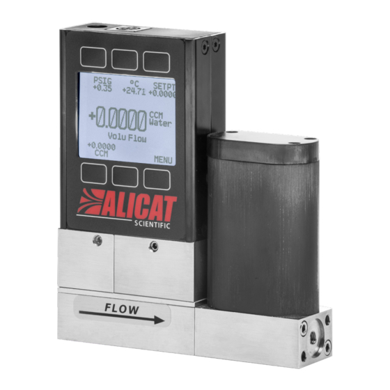
Getting Started Getting to Know Your Liquid Flow Controller The Liquid Flow Controller Display The figure to the right identifies the various features of the flow meter display. Highlights pressure in the center of the device. Highlights temperature in the center of the device ... -
Page 7: Device Ports
Device Ports Your flow controller has been shipped with plastic plugs fitted into its ports. To lessen the chance of contaminating the flow stream, do not remove these plugs until you are ready to install the device. Standard liquid flow controllers have female inlet and outlet ports. Welded VCR® and other specialty fittings may have male connections. -
Page 8: Power And Signal Connections
Power and Signal Connections Power can be supplied to your controller through either the power jack or the multi-pin connector on top of your device. ✓ Note: Power requirements vary based on analog configuration and valve type. Please reference the associated specification sheet at alicat.com/specs for power requirements. -
Page 9: Displaying Live Flow Data
Displaying Live Flow Data Main Display The main display has three primary functions: • Displaying live temperature, pressure, and flow data • Changing the flow or pressure control setpoint (page • Accessing the main menu ( MENU ) or the optional totalizer ( NEXT (page This screen displays live data for all flow parameters simultaneously. -
Page 10: Option: Collecting Totalized Flow Data
Option: Collecting Totalized Flow Data MAIN DISPLAY → NEXT (totalizer menu) The optional flow totalizer displays the total amount of mass or volume that has flowed through the instrument since its last reset, similar to a gasoline pump. It also enables batch dispensing (page 10). -
Page 11: Pausing Or Canceling A Batch
Pausing or Canceling a Batch 1. To stop flow while a batch is in progress, set the flow setpoint to zero by pressing SETPT → CLEAR → SET within the totalizer menu. This will not stop the timer. Resume flow with a non-zero set point. 2. -
Page 12: Control
Control Changing the Setpoint SETPT or MENU CONTROL Setpt: → → The setpoint selection screen indicates the engineering units and maximum allowable setpoint (e.g., LPM: +10.000 Max CLEAR To cancel a setpoint, press , then Adjusting Setpoint with an IPC For controllers ordered with a potentiometer control knob (IPC), the setpoint source must be set to analog for the controller to receive setpoint commands from the IPC (“Changing Between Setpoint Sources”... -
Page 13: Control Loop
Over a serial connection, requesting a setpoint outside the limit will be rejected and an error will be returned. When using an analog setpoint signal, setpoints that are outside of the setpoint limits are treated as if they were at the nearest limit. -
Page 14: Troubleshooting Valve Performance With Pid Tuning
Troubleshooting Valve Performance with PID Tuning The following issues can often be resolved by adjusting the PID gain values for your liquid flow controller. Fast oscillation around the setpoint • PD: Reduce the P gain in decrements of 10%. • PD²I: Increase the P gain in increments of 10%, and then adjust the I gain to fine-tune. Overshot setpoint •... -
Page 15: Setpoint Ramping
Setpoint Ramping Setpoint ramping regulates how quickly the controller will reach the flow or pressure setpoint. It is often used to prevent bursts of pressure or flow from damaging delicate instruments when starting a process. To activate setpoint ramping, you will set a maximum ramp rate and configure when to enable the ramping function. Setting the Ramp Rate Ramp •... -
Page 16: Device Information
Device Information ABOUT menu ( MENU → ABOUT ) contains useful information for setup, configuration, and troubleshooting. Basic Device Information ABOUT → About Device This includes information on the following: • MODEL : Device model SERIAL NO • : Serial number •... -
Page 17: Setup
Setup Sensor Setup MENU → SETUP → Sensor Choosing Engineering Units SETUP → Sensor → Engineering Units Changing device engineering units alters both the display and the data frame. Choose the parameter whose unit you want to change, and then select your desired engineering unit, confirming the change on the last screen. Flow and Pressure Averaging SETUP →... -
Page 18: Baud Rate
Baud Rate SETUP → RS-232 Serial or RS-485 Serial → Baud Rate Baud rate is the speed at which digital devices transfer information. The flow controller has a default baud rate of 19200 baud (bits per second). If your computer or software uses a different baud rate, you must change the flow controller’s baud rate in the BAUD menu to ensure they match. -
Page 19: Serial Communication
Serial Communication Connecting your device to a computer allows you to log the data that it generates. The device communicates digitally through its communications connector and cable using a real or virtual COM port on your computer. This section of the manual shows you how to operate the flow controller using AsCii commands. -
Page 20: Streaming Mode
Streaming Mode In streaming mode, your device automatically sends a line of live data at regular intervals. Only one unit on a given COM port may be in streaming mode at a time. To put your device into streaming mode, type: [unit ID]@=@8 Begin streaming:... -
Page 21: Quick Command Guide
by 0. To calculate your intended setpoint, use the following formula: [desired setpoint] [device FS] Integer value = 64000 × ⁄ Example: A desired setpoint of +5.44 LPM on a 10-LPM liquid flow controller is calculated as 64000 × 5.44 ⁄ 10.00 = 34816. -
Page 22: Troubleshooting
Troubleshooting If you run into trouble with installation or operation, get in touch with support (page General Use Issue: My device does not turn on, or has trouble staying on. Action: Check power and ground connections. Please reference the technical specifications to ensure you have the proper power for your model. -
Page 23: Serial Communications
Issue: Can I put the flow controller on top of a vibrating device? Will it be accurate? Action: For small valve controllers, yes you can. The device is internally compensated for any changes in orientation; however, sensor noise will increase if the flow controller is vibrating. Large-valve controllers are not recommended for use on vibrating surfaces. - Page 24 Reference Information Engineering Units For more information on engineering units, see page Flow Units Temperature Units Label Notes Label Notes µL ∕m MicroLiter per minute* °C degrees Celsius mL ∕s MilliLiter per second °F degrees Fahrenheit mL ∕m MilliLiter per minute Kelvin mL ∕h MilliLiter per hour...
- Page 25 Pinouts Check the calibration data sheet and pinout for your device. page 19 for additional important information about connecting your device to a computer for serial commands. Individual pinouts available at alicat.com/pinout. 8-Pin Mini-DIN (Default) Female Connector: Device Male Connector: Cable Pin Function Not connected Optional: 4–20 mA primary output signal...
- Page 26 9-Pin D-Sub Connector Pinouts Female Connector Male Connector DB9 (Female) DB9M (Male) DB9A / DB9K DB9R DB9T DB9U Current Out TX or B TX or B RX or A Analog Out 2 Analog Out Analog Out Analog Out Analog Out RX or A Power In Analog In...
- Page 27 15-Pin D-Sub Connector Pinouts Female Connector: Cable Male Connector: Device DB15 DB15A DB15B DB15H DB15K DB15O DB15S Ground Ground Ground Ground Ground Analog Out Analog Out Analog Out RX or A Analog Out Analog Out Ground Analog In Ground Analog Out Power In Ground Power In...
- Page 28 Geograaf 24 6921 EW Duiven The Netherlands +31 (0)26 203.1651 India india@alicat.com Halma India Pvt. Ltd. Plot No . A-147, Road No. 24, Next to Spraytech Circle opp. Metropolitan Company, Wagle Industrial Estate Thane-West Mahārāshtra 400 604 +91 022-41248010 China &...
Need help?
Do you have a question about the ALICAT LC Series and is the answer not in the manual?
Questions and answers