
Related Manuals for Halma MC Series


Summary of Contents for Halma MC Series
- Page 1 OPERATING MANUAL FOR MASS FLOW CONTROLLERS Models MC · MCD · MCE · MCQ · MCR · MCS · MCV · MCW...
- Page 2 +31 (0)26 203.1651 +1 888-290-6060 China & SE Asia India info-cn@alicat.com india@alicat.com alicat.com.cn Halma India Pvt. Ltd. 2nd Floor, Block 63, No. 421, Plot No . A-147, Road No. 24, Hong Cao Rd, Next to Spraytech Circle Shanghai 200233 opp. Metropolitan Company,...
-
Page 3: Introduction
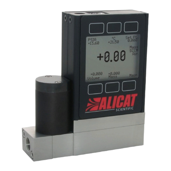
Introduction MCP-100SLPM Your new flow controller has a variety of innovative features: • High-accuracy performance for all your gases. Use your flow controller with any of the 98+ gases included with Gas Select™, page • Control pressure while monitoring flow rate. Set the closed loop control algorithm to pressure control, page... -
Page 4: Table Of Contents
Contents Introduction Setup Gas Selection Quick Start Guide Gas Select™ Getting Started Using COMPOSER™ Gas Mixes Creating New Mixes in COMPOSER™ Getting to Know Your Mass Flow Controller Viewing, Deleting, and Creating Similar Mixes The Flow Controller Display Sensor Setup Status Messages Choosing Engineering Units Mounting... -
Page 5: Quick Start Guide
Quick Start Guide Setup • Connect your flow controller. Ensure that flow will pass through your device in the same direction as the arrow on the This MC-1SLPM-D model mass flow body (usually left to right). flow controller is a typical unit. The flow body and the valve •... -
Page 6: Getting Started
Getting Started Getting to Know Your Mass Flow Controller The Flow Controller Display The figure to the right identifies the various features of the flow controller display. Highlights pressure in the center of the device. Highlights temperature in the center of the device ... -
Page 7: Device Ports
Device Ports Your controller has been shipped with plastic plugs fitted into its ports. To decrease the chance of contaminating the flow stream, do not remove these plugs until you are ready to install the device. Standard gas flow controllers have female inlet and outlet ports. VCR®-compatible and other specialty fittings may have male connections. -
Page 8: Mcv Controller Operating Notes
MCV Controller Operating Notes Alicat’s MCV mass flow controller is equipped with an integrated Swagelok® positive shutoff valve. This valve is normally closed, 60 120 Three-way but can be opened by supplying 60–120 PSIG of air pressure. PSIG solenoid valve The shut-off valve closes again when this pressure is reduced Pressure opens below 60 PSIG. -
Page 9: Power And Signal Connections
Power and Signal Connections Power can be supplied to your controller through either the power jack or the multi-pin connector on top of your device. ✓ Note: Power requirements vary based on analog configuration and valve type. Please reference the associated specification sheet at alicat.com/specs for power requirements. -
Page 10: Displaying Live Data
Displaying Live Data Main Display The main display has three primary functions: • Displaying live temperature, pressure, and flow data • Changing the flow or pressure control setpoint (page • Accessing the main menu ( MENU ) or the optional totalizer ( NEXT (page This screen displays live data for all flow parameters simultaneously. -
Page 11: Option: Color Tft Display
Option: Color TFT Display Instruments ordered with a color display are functionally the same as standard backlit monochrome instruments. The color enables additional on-screen information. Multi-Color Display Indicators • GREEN: Parameter labels and adjustments associated with the button directly above or below the label are presented in green. -
Page 12: Dispensing Gas In Batches
Dispensing Gas in Batches Batch dispensing allows you to choose a desired total volume to flow, after which the valve closes. You can repeat batches with a single button press. Starting batch dispensing BATCH 1. From the totalizer screen, press . -
Page 13: Control
Control Changing the Setpoint SETPT or MENU → CONTROL → Setpt: The control menu. The setpoint selection screen indicates the engineering units and maximum allowable SLPM: +10.000 Max CLEAR setpoint (e.g., ). To cancel a setpoint, press , then Adjusting Setpoint with an IPC For controllers ordered with a potentiometer control knob (IPC), the setpoint source must be set to analog for the controller to receive setpoint commands from the IPC (see “Changing Between Setpoint Sources”... -
Page 14: Establishing Setpoint Limits
Establishing Setpoint Limits CONTROL → Setpoint Setup → Setpoint Limits The setpoint limits menu configures upper and lower limits for selecting a flow or pressure control setpoint. By default, the controller will only be limited by its measuring range; however, more strict limits may be beneficial in certain critical applications. -
Page 15: Tuning The Pd²I Control Algorithm
Tuning the PD²I Control Algorithm The controller’s PD²I control algorithm (also called PDDI) is used to provide faster response, most commonly in dual-valve flow and pressure controllers. This algorithm uses typical PI terms and adds a squared derivative term (D): •... -
Page 16: Using A Control Deadband For Pressure Control
Using a Control Deadband for Pressure Control CONTROL → Control Loop → Control Deadband The control deadband is designed to minimize the amount of gas exhausted and improve stability. There is no active control within the deadband setting. ✓ Note: A control deadband cannot be set when the device is configured to control flow (the Control menu item within the control loop menu, see page 14). -
Page 17: Displaying Valve Drive Percentage
Displaying Valve Drive Percentage The valve drive is represented as a percentage of the amount of voltage driven to the valve. Percentages do not directly correlate with percentage open. Viewing the valve drive percentage is particularly helpful for troubleshooting. An increase in percentage over time likely indicates a clog in the system where more voltage is required to drive the valve to attain the same amount of flow. -
Page 18: Setup
Setup Gas Selection MENU → SETUP → Active Gas Gas Select™ In most cases, your flow controller was physically calibrated at the factory using air. Gas Select™ allows you to reconfigure the flow controller to flow a different gas without any need to send it back for a physical recalibration. -
Page 19: Creating New Mixes In Composer
Creating New Mixes in COMPOSER™ SETUP → Active Gas → COMPOSER Mixes → Create Mix Give the Mix a Short and Long Name . , - DOWN will change the character. Valid characters include A–Z, 0–9, punctuation ( CANCEL and space. exits to the mix settings menu. -
Page 20: Sensor Setup
Sensor Setup MENU → SETUP → Sensor Choosing Engineering Units SETUP → Sensor → Engineering Units Changing engineering units alters both the display and the data frame. Choose the parameter whose unit you want to change, and then choose an engineering unit, confirming the change on the last screen. -
Page 21: Configuring Serial Communications
Configuring Serial Communications MENU → SETUP → RS-232 Serial or RS-485 Serial You can operate the flow controller remotely via its data connection for easy streaming and logging of all data. Before connecting the flow controller to a computer, ensure that it is ready to communicate with your computer by checking the options in this menu. -
Page 22: Display Setup
Display Setup MENU → SETUP → Display The options in the display setup menu adjust the contrast/brightness of the display and enable screen rotation. Main Screen Options SETUP → Display → MAIN Screen • Any Key Press changes what happens when any of the parameter buttons on the main display (page 10) are pressed (pressure or temperature, for example). -
Page 23: Serial Communication
Serial Communication Connecting your device to a computer allows you to log the data that it generates. The device communicates digitally through its communications connector and cable using a real or virtual COM port on your computer. This section of the manual shows you how to operate the flow controller using ASCII commands. -
Page 24: Streaming Mode
Streaming Mode In streaming mode, your device automatically sends a line of live data at regular intervals. Only one unit on a given COM port may be in streaming mode at a time. To put your device into streaming mode, type: [unit ID]@=@... -
Page 25: Commanding A New Setpoint
Commanding a New Setpoint Before attempting to send a setpoint to your controller serially, confirm that its setpoint source is set to Serial/Front Panel (see page 13). There are two ways to command a new setpoint over a serial connection, as described below. In either of these methods, the data frame returns the new setpoint value when it has been accepted as a valid setpoint. -
Page 26: Quick Command Guide
Quick Command Guide Serial commands are not case-sensitive [unit ID]@=[desired ID] Change the unit ID: [unit ID]v Tare flow: Tare absolute pressure [unit ID]pc with barometer: (barometers are optional) [unit ID] Poll the live data frame: [unit ID]@=@... -
Page 27: Troubleshooting
Troubleshooting If you run into trouble with installation or operation, get in touch with support (page General Use Issue: My device does not turn on, or has trouble staying on. Action: Check power and ground connections. Please reference the technical specifications to ensure you have the proper power for your model. -
Page 28: Serial Communications
Issue: Can I put the flow controller on top of a vibrating device? Will it be accurate? Action: For small valve controllers, yes you can. The device is internally compensated for any changes in orientation; however, sensor noise will increase if the flow controller is vibrating. Large-valve controllers are not recommended for use on vibrating surfaces. -
Page 29: Reference Information
Reference Information Engineering Units For more information on engineering units, see page Pressure Units Flow Units Absolute or Volumetric Standard Normal Notes Barometric Gauge Notes µL ∕m SµL ∕m NµL ∕m Microliter per minute‡ Pascal mL ∕s SmL ∕s NmL ∕s Milliliter per second hPaA hPaG... -
Page 30: Gas List By Number
Gas List by Number To use any of these gases in your device, use Gas Select™ (page 18). Short Long Short Long Short Long Name Name Name Name Name Name Chloropentafluoroethane 173 HeOx80 80% O2, 20% He Air (Clean Dry) 101 R-115 (C2ClF5)2 ³... -
Page 31: Gas List By Category
Gas List by Category See previous page for Gas Select™ index numbers, or page 18 to configure these gases. Pure Non-Corrosive Gases Welding Gases Synthesis Gases Acetylene (C2H2) 40% H2, 29% CO, 20% CO2, 11% CH4 Air (clean, dry) 64% H2, 28% CO, 1.0% CO2, 7.0 CH4 Argon (Ar) C-10 70% H2, 4.0% CO, 25% CO2, 1.0% CH4... -
Page 32: Pinouts
Pinouts Check the calibration data sheet and pinout for your device. page 23 for additional important information about connecting your device to a computer for serial commands. Individual pinouts available at alicat.com/pinout. 8-Pin Mini-DIN (Default) Female Connector: Device Male Connector: Cable Pin Function Not Connected Optional: 4–20 mA primary output signal... -
Page 33: 9-Pin D-Sub Connector Common Pinouts
9-Pin D-Sub Connector Common Pinouts Female Connector Male Connector DB9 (F) DB9A DB9M (M) and DB9K DB9R DB9T DB9U DB9B DB9G DB9H DB9I DB9N Current Out TX or B TX or B RX or A Analog Out 2 RX or A TX or B Power In Analog Out 2 Analog Out... -
Page 34: M12 Connector Common Pinouts
M12 Connector Common Pinouts Pin M12 M12MD 0–5 Vdc Output Signal Optional: 1–5 or 0–10 Vdc Not Connected Optional: 4–20 mA primary output signal Power In Static 5.12 Vdc Optional: Secondary analog output (4–20 mA, 0–5 Vdc, 1–5 Vdc, 0–10 Vdc) or basic alarm Serial RS-232 RX signal Optional: RS-485 A Serial RS-232 RX Signal... - Page 35 2021.05.25 • REV. 4 • MASS FLOW CONTROLLER OPERATING MANUAL...
- Page 36 Main Display Main Menu page 10 page 10 ABOUT About Menu page 17 MENU CONTROL SETUP NEXT Setup page 18 Totalizer page 11 Gas Select™ page 18 Active Control page 13 Sensor Setup page 20 Setpoint page 13 Sensor Serial Comm. page 21 Setpt Setpoint Setup...
Need help?
Do you have a question about the MC Series and is the answer not in the manual?
Questions and answers