
Related Manuals for Halma MC Series


Summary of Contents for Halma MC Series
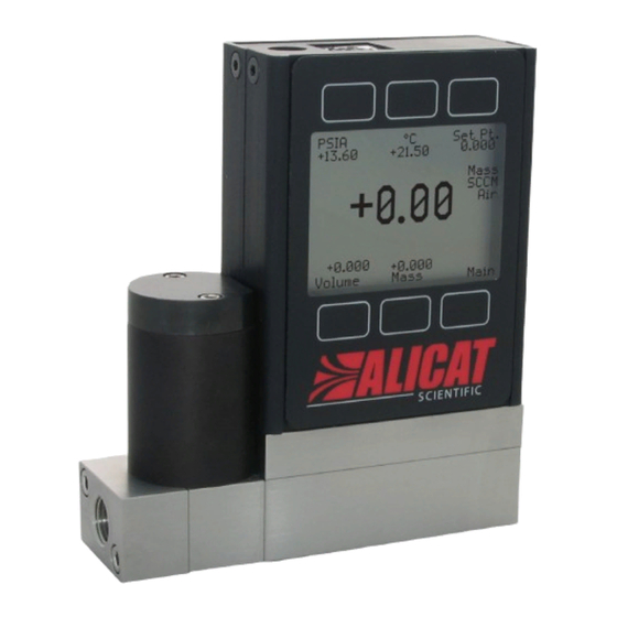
- Page 1 The Fastest Flow Controller Company in the World! OPERATING MANUAL MC · MCW · MCR · MCV...
- Page 2 Thank you for purchasing an Alicat flow controller. If you have any questions about operating it, or if something is not working as expected, please let us know. We are eager to help you in any way possible. Alicat Scientific, Inc. info@alicat.com •...
- Page 3 Introduction You’re busy, and the last thing you want to do is waste time wrestling with your flow controller. We’re here to make your life a little easier so you can do what you do best. It’s our pleasure to introduce you to your new Alicat: •...
-
Page 4: Table Of Contents
Contents Quick Start Guide Getting Started Getting to Know Your Alicat Connectors and Buttons The Flow Controller Display Status Messages Mounting Filters Device Ports Connecting Plumbing to Your Gas Flow Controller MCV Controller Operating Notes MCD Dual Valve Controller Operating Notes Power and Signal Connections Standard 8-Pin Mini-DIN Pinout Analog Signals... - Page 5 About Diagnostic Information Basic Configuration Menu Choosing Engineering Units from the Basic Configuration Serial Communication Establishing Communications Serial Terminal Application Polling Mode Streaming Mode Taring Collecting Flow Data Commanding a New Setpoint Sending Setpoints as Floating Point Numbers Sending Setpoints as Integers Using Gas Select™...
-
Page 6: Quick Start Guide
Quick Start Guide Setup • Connect your flow controller. Ensure that flow through your device will be in the same direction as the arrow on the flow body (usually left to right). • Tare your flow controller. Before you connect the flow meter, ensure that no air is flowing through the device and give it a zero setpoint for at least 2 seconds. -
Page 7: Getting Started
Connectors and Buttons The drawings below represent the default configuration of a standard Alicat mass flow controller (MC series) with an upstream valve. Your flow controller’s appearance and connections may differ, especially if it has been ordered with a large Rolamite valve or a downstream valve. -
Page 8: The Flow Controller Display
The Flow Controller Display The figure below identifies the various features of the flow controller display. Press the large button with the Alicat logo to toggle the backlight on and off. For more details, see the Menu Map on page 16 and the menu-by-menu descriptions that follow it. -
Page 9: Mounting
Mounting No straight runs of pipe are required upstream or downstream of the flow controller. Most Alicat flow controllers can be mounted in any position, including upside-down. MCS and MCRS series flow controllers use media-isolated sensors that must be tared after changing orientation. Caution: Flow controllers that use large Rolamite valves (MCR, MCRW, MCRQ, MCRS) should be mounted with their valve oriented vertically (right-side up). -
Page 10: Connecting Plumbing To Your Gas Flow Controller
Connecting Plumbing to Your Gas Flow Controller Your Alicat flow controller can measure and control flow generated by positive pressure and/or suction. Connect the controller so that the flow travels in the same direction as the flow arrow, usually from left to right as you look at the front of the device. -
Page 11: Mcv Controller Operating Notes
When the solenoid is returned to a relaxed state, the gas vents to atmosphere, allowing the shut-off valve to close. ✓ All standard MC-Series device features and functions are available on the MCV Series and operate in accordance with the standard MC Series operating instructions. 60 120 Three-way PSIG solenoid valve... -
Page 12: Mcd Dual Valve Controller Operating Notes
MCD Dual Valve Controller Operating Notes The MCD is a versatile Dual-Valve Mass Flow and Pressure Controller. It can be used to: • Measure mass flow and volumetric flow in both directions, plus absolute pressure and temperature. • Control mass or volumetric flow from a pressurized source or to vacuum. -
Page 13: Power And Signal Connections
Power and Signal Connections Power can be supplied to your controller through either the power jack or the multi-pin connector on top of your device. ✓ Small valve controller power jacks require a 12–24 Vdc power supply with a 2.1 mm female positive center plug capable of supplying at least 250 mA. -
Page 14: Analog Signals
Analog Signals Primary Analog Output Signal Most Alicat instruments include a primary analog output signal, which is linear over its entire range. For both standard 0–5 Vdc and optional 0–10 Vdc output signals, a zero flow condition is usually in the range of 0.010 Vdc. Zero flow for the optional 1–5 Vdc and 4–20 mA output signals is 1 Vdc and 4 mA, respectively. -
Page 15: Option: Color Tft Display
Option: Color TFT Display Instruments ordered with a color display function the same as standard backlit monochrome instruments, but color is used to provide additional on-screen information. Multi-Color Display Indicators • GREEN: Parameter labels and adjustments associated with the button directly above or below the label are presented in green. •... -
Page 16: Navigation And Customization
Navigation and Customization Start Here Main Display Flow Controller Menu Map SLPM PSIA SETPT TOTAL/ SETPT +15.44 +13.60 +24.38 +15.44 TIMER +15.44 M AVG +15.44 SL +15.44 SLPM +45.29 Optional Flow 2:56 h:m:s Mass Flow Totalizer +16.67 +15.44 TOTAL/ +14.71 MENU/ SLPM MENU... -
Page 17: Displaying Live Flow Data
Displaying Live Flow Data The Main Display has three primary functions: • Displaying live temperature, pressure, and flow data (see below) • Changing engineering units for temperature, pressure, and flow (page 18) • Changing the flow or pressure control setpoint (page 24) This screen displays live data for all flow parameters simultaneously. -
Page 18: Choosing Engineering Units
Choosing Engineering Units Press the button next to any of the four flow parameters twice to enter its unit selection menu. You can change units in two ways: DOWN Show abs pressure Button engineering units alter the display > Show gauge pressure Show baro pressure only, not the serial data: Set button eng units... -
Page 19: Option: Totalized Flow Data And Batch Dispensing
Option: Totalized Flow Data and Batch Dispensing Your flow controller may have an optional flow totalizer, which enables batch dispensing. The totalizer displays the total amount of mass or volume that has flowed through the instrument since its last reset, like a gasoline pump. Access TOTAL/MENU the totalizer screen by pressing on the Main Display. -
Page 20: Dispensing Gas In Batches
Dispensing Gas in Batches Batch dispensing allows you to choose a desired total volume to flow, after which the valve closes. You can repeat batches with a single button press. Totalizer – Batch Mode SETPT Displays the current setpoint. Flow stops as Batch dispensing can begin only soon as the batch when there is a non-zero setpoint. - Page 21 How to repeat a batch y press • For a new batch of identical size, simpl RESET . Flow begins immediately. • For a new batch of a different size, press BATCH , and then select the new batch size. Flow begins as soon as you press How to cancel a batch 1.
-
Page 22: Menu
Menu MENU Enter the menu system by pressing the button from the Main Display. ABOUT Enters the About Menu (page 32). TARES Enter the Tares Menu (page 22) CONTROL ABOUT TARES TARE TARE AUTO CONTROL Enters the Control FLOW PRESS TARE Menu (page 23). -
Page 23: Control Menus
Control Menus CONTROL ADV CONTROL menus allow you to command new setpoints, change the setpoint control loop, and adjust proportional integral and derivative (PID) control settings, among other options. → Menu Control SETPT RAMP Activates and SETPT Displays the current sets the speed of setpoint setpoint. -
Page 24: Changing The Setpoint
Changing the Setpoint Press the SETPT button from either the Main Display or the Control Menu MENU CONTROL ) to choose a new setpoint. The setpoint selection screen indicates the engineering units and maximum allowable setpoint (e.g., SLPM 20.00 Max ). -
Page 25: Establishing Setpoint Limits
Establishing Setpoint Limits The Setpoint Limits Menu lets you set up upper and lower limits for selecting a flow or pressure control setpoint. To access this menu, select → → → → MENU CONTROL ADV CONTROL CONTROL OPTS SETPT LIMITS •... -
Page 26: Using Setpoint Ramping
Using Setpoint Ramping Setpoint ramping regulates how quickly your mass flow controller will reach the requested flow or pressure setpoint. This feature is especially useful when you need to prevent sudden bursts of pressure or flow from hitting delicate instruments when you start up your process. To activate setpoint ramping, you need to set a maximum ramp rate, and you need to configure when to enable the ramping function. - Page 27 Enabling the Setpoint Ramping Function Your flow controller enables the ramping function independently for changes that require increases or decreases to achieve the new setpoint. For example, you can enable ramping up to a flow setpoint to prevent flow from building too quickly, but disable ramping down so that you can stop flow immediately.
-
Page 28: Limiting Flow Rate While Controlling Pressure
Limiting Flow Rate While Controlling Pressure When the control loop variable is set to control pressure, setpoint ramping regulates how quickly it reaches the pressure setpoint by limiting how quickly the measured pressure can change. This provides direct control of pressure. To limit flow rates directly while controlling pressure, set up flow limiting →... -
Page 29: Adjusting The Closed Loop Controller
Adjusting the Closed Loop Controller Your mass flow controller uses an electronic closed loop controller to deter- mine how to actuate its valve(s) in order to achieve the commanded setpoint. We have tuned these settings for your specific operating conditions, but changes to your process sometimes require on-site adjustments to maintain optimal control performance. - Page 30 Tuning the PD2I control algorithm Alicat’s PD2I control algorithm (also called PDDI) is used to provide faster response, most commonly in dual-valve flow and pressure controllers. This algorithm uses typical PI terms and adds a squared derivative term (D): • The larger the P gain, the more aggressively the controller will correct errors between the commanded setpoint and the measured process value.
-
Page 31: Using A Control Deadband For Mcds
Using a Control Deadband for MCDs The control deadband is designed for use with closed-volume pressure control applications to minimize the amount of gas exhausted. The deadband defines a region above and below the setpoint within which the process variable is permitted to deviate from the setpoint. Example: When controlling pressure in a closed volume with a setpoint of 30 psia, a deadband of ±1 psia would allow the absolute pressure to vary between 29 and 31 psia before actively controlling the valves to the setpoint. -
Page 32: About
About We hope you don’t run into trouble using your flow controller, but if you do, ABOUT menu contains information that can make the troubleshooting process easier. Select MFG INFO to look up Alicat’s phone number and web DEVICE INFO address. -
Page 33: Basic Configuration Menu
Basic Configuration Menu The Basic Configuration Menu contains options for choosing the gas calibration, device engineering units and STP/NTP mass flow references. → Menu Basic Configuration DEVICE UNITS Changes device engineering units for any parameter: GAS Enters Gas Select™ and Mass Flow - Volumetric Flow - COMPOSER™... - Page 34 Gas Select™ In most cases, your flow controller was physically calibrated on air at Alicat’s factory. Gas Select™ allows you to reconfigure the flow controller to flow a different gas without sending it back to Alicat for a physical recalibration. To use Gas Select™, simply choose a gas or gas mix from one of the listed categories.
- Page 35 Gas List Your Alicat is preloaded with gas properties data for the following gases: Pure Non-Corrosive Gases Stack/Flue Gas Mixes Acetylene (C2H2) 2.5% O2, 10.8% CO2, 85.7% N2, 1% Ar Air (Clean Dry) 2.9% O2, 14% CO2, 82.1% N2, 1% Ar Argon (Ar) 3.7% O2, 15% CO2, 80.3% N2, 1% Ar Isobutane (i-C4H10)
- Page 36 Using COMPOSER™ to Create Custom Gas Mix Compositions To remain accurate, your flow controller needs to know the viscosity of the gas you are flowing through it. The more closely you can define your actual gas composition, the more accurate your flow readings will be. Alicat’s COMPOSER™...
- Page 37 Adding a new COMPOSER™ mixed gas composition Generate and store a new COMPOSER™ mix in 3 easy steps. ✓ Note: You cannot save your mix until the total is 100%. Saved gas compositions can be deleted, but not modified. DOWN EDIT % DOWN NEXT...
- Page 38 Defining STP/NTP Reference Values Standardized flow rates are reported in “standard” or “normal” volumetric flow units that reference a given temperature and pressure combination. This reference is called an STP (standard temperature and pressure) or, typically in Europe, an NTP (normal temperature and pressure). →...
- Page 39 Advanced Setup The Advanced Setup Menu lets you configure the display, zero band, averaging (for flow and pressure), and serial communications. → Menu Advanced Setup SENSOR SETUP Enters the Sensor COMM SETUP Enters the Communications DISP SETUP Enters the Display Setup Menu (page 40).
- Page 40 Sensor Setup Sensor Setup Menu contains advanced settings that govern how the flow and pressure sensors report their data. → → Menu Advanced Setup Sensor Setup DISPLAY AS ZERO Defines the NUM OF DIGITS Sets the number deadband threshold under of significant digits to display which flow values are flow readings on-screen and...
- Page 41 Configuring Serial Communications You can operate the flow controller remotely via serial communication for easy streaming and logging of all data. Before connecting the flow controller to a computer, ensure that it is ready to communicate with your COMM SETUP computer by checking the options in the menu.
-
Page 42: Serial Communication
Serial Communication Connecting your flow controller to a computer allows you to log the data that it generates. The flow controller communicates digitally through its communications connector and cable using a real or virtual COM port on your computer. This section of the manual shows you how to operate the flow controller using ASCII commands. -
Page 43: Polling Mode
Polling Mode Your flow controller was shipped to you in polling mode with a unit ID of A, unless requested otherwise. Polling the flow controller returns a single line of data each time you request it. To poll your flow controller, simply enter its unit ID. -
Page 44: Taring
Taring Before collecting flow data, be sure to tare your flow controller. If auto-tare is enabled, this can be accomplished by provided a setpoint of 0 for at least 2 seconds. Manual taring can be accomplished serially through two separate commands. -
Page 45: Commanding A New Setpoint
Commanding a New Setpoint Before attempting to send setpoints to your mass flow controller serially, confirm that its setpoint source is set to Serial/Front Panel by selecting → → → MENU CONTROL ADV CONTROL SETPT SOURCE There are two ways to command a new setpoint over a serial connection, as described below. -
Page 46: Using Gas Select™ And Composer
Using Gas Select™ and COMPOSER™ To reconfigure your flow controller to flow a different gas, look up its Gas Number (see “Gas List” on page 52). Then type: [unit ID]g[Gas Number] Choose a gas: ag8 Example 1: (reconfigures to flow nitrogen) ag206... -
Page 47: Quick Command Guide
Quick Command Guide ✓ Note: Serial commands are not case-sensitive. For simplicity, we assume that the unit ID of the flow controller when not streaming is a in the listing that follows. a@=[desired unit ID] Change the unit ID: av Tare flow: Tare absolute pressure apc... -
Page 48: Troubleshooting
Troubleshooting If you run into any trouble with your Alicat’s installation or operation, please get in touch with us by phone, chat, or email. You’ll also find help on our website alicat.com and in the pages that follow. General Use Issue: My Alicat does not turn on, or has trouble staying on. - Page 49 Flow Readings Issue: The live flow readings won’t settle down. Action: The flow controller is very fast, so it can detect subtle variations in flow that may go unnoticed by your other flow devices. This sensitivity can help detect problems with pumps or flow controllers.
- Page 50 Issue: My controller does not agree with another mass flow meter I have in line. → → MENU BASIC CONFIG STP/NTP Action: Check the STP or NTP settings ( to ensure that your standardized temperature and pressure references match those of your other flow calibrator. Also check that your device’s Gas Select™...
-
Page 51: Maintenance
Maintenance Cleaning Your flow controller requires no periodic cleaning, provided that it has been flowing clean, dry gas. If necessary, the outside of the device can be cleaned with a soft dry cloth. Alicat also offers remote panels and ingress protection for some models used in hazardous or remote applications. -
Page 52: Gas List
Gas List Short Long Short Long Name Name Name Name Air (Clean Dry) Sulfur Dioxide C3H6 Propylene Argon 1Buten 1-Butylene2 Methane cButen Cis-Butene (cis-2-Butene) Carbon Monoxide iButen Isobutylene Carbon Dioxide tButen Trans-2-Butene C2H6 Ethane Carbonyl Sulfide Hydrogen Dimethylether (C2H6O) Helium SiH4 Silane Nitrogen... - Page 53 Short Long Short Long Name Name Name Name 183 HeNe-9 9% Ne, 91% He 148 Bio20M 20% CH4, 80% CO2 184 LG-9.4 9.4% CO2, 19.25% N2, 71.35% He 149 Bio25M 25% CH4, 75% CO2 185 SynG-1 40% H2, 29% CO, 20% CO2, 11% CH4 150 Bio30M 30% CH4, 70% CO2 186 SynG-2 64% H2, 28% CO, 1% CO2, 7% CH4 151 Bio35M 35% CH4, 65% CO2...
-
Page 54: Engineering Units
Engineering Units True Mass Flow Units Flow Units Label Notes Volumetric Std. Normal Notes milligram per uL ∕m SuL ∕m NuL ∕m microliter per minute mg ∕s second mL ∕s SmL ∕s NmL ∕s milliliter per second mg ∕m milligram per minute mL ∕m SmL ∕m NmL ∕m... -
Page 55: Pressure Units
Pressure Units Absolute or Barometric Gauge Notes pascal hPaA hPaG hectopascal kPaA kPaG kilopascal MPaA MPaG megapascal mbarA mbarG millibar barA barG g∕cm2A g∕cm2G gram force per square centimeter kg∕cmA kg∕cmG kilogram force per square centimeter PSIA PSIG pound force per square inch PSFA PSFG pound force per square foot... -
Page 56: Optional Pinouts
Optional Pinouts Additional Pinouts Individual pinouts available at www.alicat.com/pinout ✓ Due to variance in cable manufacturing, please identify proper wiring/pins via continuity check & color when using blunt cut multi-strand cables. Locking Industrial Connector Pinouts If your Alicat Instrument was ordered with a Six Pin Locking Industrial connection, please be sure to reference the following pinout diagram. -
Page 57: M12 Connector Pinouts
M12 Connector Pinouts If your Alicat Instrument was ordered with the M12 connection, please be sure to reference the following pin-out diagram. M12 Connector Male Pin Function 0–5 Vdc (or optional 0–10 Vdc) Output Signal Power In +24 VDC, 1 A recommended for most models Serial RS-232 RX / RS-485( −... -
Page 58: Pin D-Sub Common Pinouts
9 pin D-Sub Common Pinouts If your instrument was ordered with a DB9 connection, be sure to check the calibration label on the device or the calibration data sheet and reference the appropriate pinout diagram. Male Connector: Cable Female Connector: Device Common 9-pin D-Sub Pinouts DB9 (Female) DB9A /... -
Page 59: 15 Pin D-Sub Common Pinouts
15 pin D-Sub Common Pinouts If your instrument was ordered with a DB15 connection, be sure to check the calibration label on the device or the calibration data sheet and reference the appropriate pinout diagram. Male Connector: Cable Female Connector: Device Pin DB15 DB15A DB15B DB15H DB15K DB15O DB15S Key of Terms:... - Page 60 Additional Information for Alicat CSA and ATEX Approved Devices II 3 G EEx nA IIC T4 Class I, Div. 2 Group A, B, C and D T4 24 Vdc, 0.800A max Class I, Zone 2 AEx nA IIC T4 WARNINGS: EXPLOSION HAZARD –...
- Page 61 II 3 G EEx nA IIC T4 Class I, Div. 2 Group A, B, C and D T4 24 Vdc, 0.800A max Class I, Zone 2 AEx nA IIC T4 X – See manual for special conditions WARNINGS: EXPLOSION HAZARD – DO NOT DISCONNECT WHILE CIRCUIT IS LIVE UNLESS AREA IS KNOWN TO BE NON- HAZARDOUS.
- Page 62 Limited Lifetime Warranty Alicat Scientific, Inc. warrants to the original of Alicat’s rendering of technical advice in connec- purchaser (hereinafter referred to as “Buyer”) tion with Buyer’s order of the Products furnished that instruments manufactured by Alicat Scientific hereunder. (hereinafter referred to as “Product”) shall be free If Product becomes obsolete, Alicat Scientific, from defects in materials and workmanship for the at its own discretion, reserves the right to repair...
- Page 63 2020.02.05 • REV. 0...
- Page 64 Flow Controller Menu Map Start Here Main Display SLPM PSIA SETPT TOTAL/ SETPT +15.44 +13.60 +24.38 +15.44 TIMER +15.44 M AVG +15.44 SL +15.44 +45.29 SLPM Optional Flow 2:56 h:m:s Mass Flow Totalizer +16.67 +15.44 TOTAL/ +14.71 MENU/ SLPM MENU REMAIN RESET MAIN...
Need help?
Do you have a question about the MC Series and is the answer not in the manual?
Questions and answers