Table of Contents
Advertisement
Quick Links
Advertisement
Table of Contents

Related Manuals for Halma ALICAT SCIENTIFIC PC Series


Summary of Contents for Halma ALICAT SCIENTIFIC PC Series
- Page 1 OPERATING MANUAL FOR PRESSURE CONTROLLERS Models PC · PCS · PC3 · IVC...
- Page 2 +31 (0)26 203.1651 +1 888-290-6060 China & SE Asia India info-cn@alicat.com india@alicat.com alicat.com.cn Halma India Pvt. Ltd. 2nd Floor, Block 63, No. 421, Plot No . A-147, Road No. 24, Hong Cao Rd, Next to Spraytech Circle Shanghai 200233 opp. Metropolitan Company, Wagle Industrial Estate +86-21-60407398 ext.
-
Page 3: Introduction
Introduction Your pressure controller has many innovative features: • 1000 readings per second guarantees high resolution data, page PCP-5PSID • Backlit display with adjustable contrast is easy to read even in direct sunlight. In dimly lit areas, press the logo to turn on the backlight, page •... -
Page 4: Table Of Contents
Contents Introduction Serial Communication Modbus RTU Communication Quick Start Guide Establishing Communication Getting Started Polling Mode Streaming Mode Getting to Know Your Pressure Controller Taring The Pressure Controller Display Collecting Data Status Messages Mounting Commanding a New Setpoint Filters Sending Setpoints as Floating Point Numbers Quick Command Guide Device Ports Connecting Your Pressure Controller... -
Page 5: Quick Start Guide
Quick Start Guide Setup This is a typical gauge pressure configuration. • Connect your pressure controller. Ensure that flow will pass through your device in the same direction as the arrow on the flow body (usually left to right). • Choose your engineering units. You can choose the measurement units by selecting MAIN MENU →... -
Page 6: Getting Started
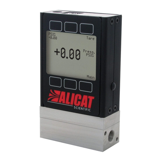
Getting Started Getting to Know Your Pressure Controller The Pressure Controller Display The figure below identifies the various features of the main pressure controller display. Highlights pressure in the center of the display. Tares the pressure (typically unavailable for abso- lute pressure devices) (page 11). -
Page 7: Device Ports
Device Ports Your pressure controller has been shipped with plastic plugs fitted into its ports. To decrease the chance of contaminating the flow stream, do not remove these plugs until you are ready to install the device. Standard pressure controllers have female inlet and outlet ports. VCR® and other specialty fittings may have male connections. -
Page 8: Forward (Downstream) Pressure Control
Applications Forward (Downstream) Pressure Control When the valve is located on the upstream side (direct control), the sensor will control pressure downstream. This configuration follows our standard pressure control algorithm. Note: the valve opens to increase pressure, and closes to decrease pressure. Example: Upstream Valve Gas Supply Pressure Regulator... -
Page 9: Remote-Sensing Controller
Remote-Sensing Controller PC3-Series models sense and control the pressure at some point in the system outside of the pressure controller itself. All PC-Series controllers can be ordered with an additional NPT port on the front, which is connected directly to the pressure sensor in the device. The pressure sensor is isolated from the flow path in this configuration. -
Page 10: Power And Signal Connections
Power and Signal Connections Power can be supplied to your controller through either the power jack or the multi-pin connector on top of your device. ✓ Note: Power requirements vary based on analog configuration and valve type. Please reference the associated specification sheet at alicat.com/specs for power requirements. -
Page 11: Displaying Live Data
Displaying Live Data Main Display The main display has four primary functions: • Displaying live pressure data • Setting the pressure controller’s setpoint • Taring the pressure (page • Accessing the main menu ( MENU Live data is measured 1000 times per second, and the LCD display is updated 10 times per second. -
Page 12: Control
Control Changing the Setpoint SETPT or MENU CONTROL Setpt: → → The setpoint selection screen indicates the engineering units and maximum allowable The control menu. PSIG: +10.000 Max CLEAR setpoint (e.g., ). To cancel a setpoint, press , then Adjusting Setpoint with an IPC For controllers ordered with a potentiometer control knob (IPC), the setpoint source must be set to analog for the controller to receive setpoint commands from the IPC (see “Changing Between Setpoint Sources”... -
Page 13: Establishing Setpoint Limits
Power-Up Setpoint with Ramping CONTROL → Setpoint Setup → Power Up Setpoint → Ramp Any setpoint ramp will always start from zero on power-up. Similar to the zero setpoint option (page 12), the device can either honor the ramp rate ( Honor from 0 ) or jump to setpoint Jump from 0... -
Page 14: Tuning The Pd²I Control Algorithm
Tuning the PD²I Control Algorithm The controller’s PD²I control algorithm (also called PDDI) is used to provide faster response, most commonly in dual-valve flow and pressure controllers. This algorithm uses typical PI terms and adds a squared derivative term (D): •... -
Page 15: Setpoint Ramping
Setpoint Ramping Setpoint ramping regulates how quickly the controller will reach the pressure setpoint. It is often used to prevent bursts of flow from damaging delicate instruments when starting a process. To activate setpoint ramping, you will set a maximum ramp rate and configure when to enable the ramping function. -
Page 16: Device Information
Device Information ABOUT menu ( MENU → ABOUT ) contains useful information for setup, configuration, and troubleshooting. Basic Device Information ABOUT → About Device This includes information on the following: • MODEL : Device model • SERIAL NO : Serial number The about menu. -
Page 17: Setup
Setup Sensor Setup MENU → SETUP → Sensor Choosing Engineering Units SETUP → Sensor → Engineering Units Changing device engineering units alters both the display and the data frame. Choose the parameter whose unit you want to change, and then select your desired engineering unit, The setup menu. -
Page 18: Configuring Serial Communications
Configuring Serial Communications MENU → SETUP → RS-232 Serial or RS-485 Serial You can operate the pressure controller remotely via its data connection for easy streaming and logging of all data. Before connecting the pressure controller to a computer, ensure that it is ready to communicate with your computer by checking the options in this menu. -
Page 19: Display Setup
Display Setup MENU → SETUP → Display The options in the display setup menu adjust the contrast/brightness of the display and enable screen rotation. Main Screen Options SETUP → Display → MAIN Screen • Any Key Press changes what happens when any of the parameter buttons on the main The display setup menu. -
Page 20: Serial Communication
Serial Communication Connecting your device to a computer allows you to log the data that it generates. The pressure controller communicates digitally through its communications connector and cable using a real or virtual COM port on your computer. This section of the manual shows you how to operate the pressure controller using ASCII commands. -
Page 21: Streaming Mode
Streaming Mode In streaming mode, your device automatically sends a line of live data at regular intervals. Only one unit on a COM port may be in streaming mode at a time. To put your pressure controller into streaming mode, type: [unit ID]@=@... -
Page 22: Commanding A New Setpoint
Commanding a New Setpoint Before attempting to send a setpoint to your controller serially, confirm that its setpoint source is set to Serial/Front Panel (page 12). There are two ways to command a new setpoint over a serial connection, as described below. In either of these methods, the data frame returns the new setpoint value when it has been accepted as a valid setpoint. - Page 23 Troubleshooting If you run into trouble with your device’s installation or operation, please get in touch with us by phone, chat, or email (page 2). You’ll also find help on our website, alicat.com/support, and in the pages that follow. General Use Issue: My device does not turn on or has trouble staying on.
- Page 24 Issue: My pressure controller disagrees with another device I have in line. Action: Pressure devices can normally be compared against one another provided there are no leaks between the two devices. Another possibility is an improper tare error (page 11). Issue: Can I use the controller with other gases or liquids? Action: Yes for gases, maybe for liquids.
- Page 25 Reference Information Engineering Units Pressure Units Absolute or Barometric Gauge Differential Notes Pascal hPaA hPaG hPaD Hectopascal kPaA kPaG kPaD Kilopascal MPaA MPaG MPaD Megapascal mbarA mbarG mbarD Millibar barA barG barD g∕cm2A g∕cm2G g∕cm2D Gram force per square centimeter† kg∕cm²A kg∕cm²G kg∕cm²D...
- Page 26 Pinouts Check the calibration data sheet and pinout for your device. page 20 for additional important information about connecting your device to a computer for serial commands. Individual pinouts available at alicat.com/pinout. 8-Pin Mini-DIN (Default) Female Connector: Device Male Connector: Cable Pin Function Not Connected Optional: 4–20 mA primary output signal...
- Page 27 9-Pin D-Sub Connector Pinouts Female Connector Male Connector (Female) DB9A / DB9M (Male) DB9K DB9R DB9T DB9U DB9G DB9H DB9I DB9N Current Out TX or B TX or B RX or A RX or A TX or B Power In Analog Out 2 Analog Out Analog Out...
- Page 28 M12 Connector Pinouts Pin M12 M12MD Not Connected 0–5 Vdc Output Signal Optional: 1–5 or 0–10 Vdc Optional: 4–20 mA primary output signal Static 5.12 Vdc Power In Optional: Secondary analog output (4–20 mA, 0–5 Vdc, 1–5 Vdc, 0–10 Vdc) or basic alarm Serial RS-232 RX signal Optional: RS-485 A Serial RS-232 RX Signal...
- Page 30 Geograaf 24 6921 EW Duiven The Netherlands +31 (0)26 203.1651 India india@alicat.com Halma India Pvt. Ltd. Plot No . A-147, Road No. 24, Next to Spraytech Circle opp. Metropolitan Company, Wagle Industrial Estate Thane-West Mahārāshtra 400 604 +91 022-41248010 China &...
Need help?
Do you have a question about the ALICAT SCIENTIFIC PC Series and is the answer not in the manual?
Questions and answers