Table of Contents
Advertisement
Quick Links
Quick Start
Overview
f
WARNING!
Read all warnings, cautions, notes and installation instructions before installing or servicing this equipment.
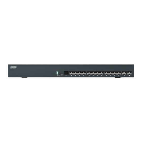
This quick start describes how to install, configure, and troubleshoot the NetVanta 1760-12F, a Multi-Gigabit fiber aggregation switch that includes 12 multi-
rate SFP+ ports (1G/2.5G/5G/10G) and 2 multi-rate SFP28 ports (1G/2.5G/5G/10G/25G). Figures 1 and 2 show the Front and Rear Panel layouts of the
switch.
■
"Installing the Switch"
on page 2
■
"Supplying Power to the Switch"
■
"Connecting to the Switch"
■
"Understanding the Status LEDs"
■
"Resetting the Switch"
on page 7
■
"Troubleshooting the Switch"
■
"Product Specifications"
on page 8
Figure 1. Front Panel Layout
Figure 2. Rear Panel Layout
f
WARNING!
WARNING indicates a hazard which, if
not avoided, could result in death, injury
or serious property damage.
NetVanta 1760-12F
Multi-Gigabit Fiber Aggregation Switch
on page 3
on page 5
on page 7
on page 8
SYS
LED
Reset
Button
f
CAUTION!
CAUTION indicates a hazard which, if not
avoided, could result in service interruption,
damage to the equipment, or minor property
damage.
CONSOLE
Port
10G SFP+
Ports
Port Status (LAN)
AC Line: 100-240V 50-60 Hz
Power Connection
AC Power Supply
October 2021
617101763F1-13A
P/N: 17101763F1
25G SFP28
Ports
LEDs
Slot for Secondary
Hot-swappable
AC Power Supply
Sold Separately;
(PN 17101760PF1)
g
NOTE
NOTES inform the user of additional, but
important, information or features.
Advertisement
Table of Contents

Related Manuals for ADTRAN NetVanta 1760-12F


Summary of Contents for ADTRAN NetVanta 1760-12F
- Page 1 Read all warnings, cautions, notes and installation instructions before installing or servicing this equipment. This quick start describes how to install, configure, and troubleshoot the NetVanta 1760-12F, a Multi-Gigabit fiber aggregation switch that includes 12 multi- rate SFP+ ports (1G/2.5G/5G/10G) and 2 multi-rate SFP28 ports (1G/2.5G/5G/10G/25G). Figures 1 and 2 show the Front and Rear Panel layouts of the switch.
-
Page 2: Installing The Switch
CAUTION! The NetVanta 1760-12F is intended for indoor use only. Ethernet, PoE cables, and attached equipment are intended for use within the same building with equipotential bonding, and not intended to be placed in separate buildings or structures. Failure to deploy as described could result in permanent damage from lightning or other electrical events and voids the warranty. -
Page 3: Supplying Power To The Switch
NOTE Rack mount brackets are a default accessory with the unit; spare brackets can be ordered through ADTRAN, part number: 1700519F1. Figure 4. Attaching Brackets to the Rack Post Mounting the Switch on a Desk or Shelf To mount the switch on a desk or shelf, complete the following steps. - Page 4 NOTE For mission critical applications where downtime needs to be minimized, the NetVanta 1760-12F supports a hot-swappable redundant AC power supply to protect against a single power supply failure.The redundant power supply is not included in the base shipment of the NetVanta 1760-12F, but it can be ordered directly from ADTRAN (P/N 17101760PF1).
-
Page 5: Connecting To The Switch
This product is intended for use with a Class 1 Laser module that complies with FDA 21 CFR 1040.10, 1040.11 and IEC 60825-1. For continued compliance with the above standards, only approved Class 1 Laser modules from an ADTRAN approved vendor list (located on the ADTRAN website) should be installed in this product. - Page 6 c. Select Change adapter settings on the left of PC screen. NOTE Users can also skip Steps 1-2, by pressing WinKey+R and typing the ncpa.cpl command to get to Step 4 directly. ■ Right-click on your local adapter and select Properties. ■...
-
Page 7: Understanding The Status Leds
Understanding the Status LEDs The LEDs on the front panel provide you with switch status checking and monitoring. The following section describes the three types of LEDs. SYSTEM Status LED The SYSTEM Status LED indicates if the switch is powered up correctly or if a system alarm has been triggered for troubleshooting. Color State Description... -
Page 8: Troubleshooting The Switch
■ 2. This device must accept any interference received, including interference that may cause undesired operation. ■ Changes or modifications not expressly approved by ADTRAN could void the user's authority to operate this equipment. NOTE This equipment has been tested and found to comply with the limits for a Class A digital device, pursuant to part 15 of the FCC Rules. - Page 9 ADTRAN CUSTOMER CARE: Warranty: ADTRAN will replace or repair this product within the warranty period if it does not meet its published specifications or fails while in service. Warranty information can be From within the U.S. 1.888.423.8726 found online at www.adtran.com/warranty.
Need help?
Do you have a question about the NetVanta 1760-12F and is the answer not in the manual?
Questions and answers