Table of Contents
Advertisement
Quick Links
HYPONIC DRIVE®
《CAUTION》
■Gearmotors and reducers should be handled, installed, and maintained by trained technicians.
Carefully read the instruction manual before use.
■A copy of this instruction manual should be sent to the actual user.
■This instruction manual should be retained by the user for future reference.
Instruction Manual
No.NM2201E-6
Advertisement
Table of Contents

Related Manuals for Sumitomo Drive Technologies HYPONIC DRIVE


Summary of Contents for Sumitomo Drive Technologies HYPONIC DRIVE
- Page 1 HYPONIC DRIVE® 《CAUTION》 ■Gearmotors and reducers should be handled, installed, and maintained by trained technicians. Carefully read the instruction manual before use. ■A copy of this instruction manual should be sent to the actual user. ■This instruction manual should be retained by the user for future reference. Instruction Manual No.NM2201E-6...
- Page 2 Safety and Other Precautions G Carefully read this maintenance manual and all accompanying documents before use (installation, operation, maintenance, inspection, etc.). Thoroughly understand the machine, information about safety, and all precautions for correct operation. Retain this manual for future reference. G Pay close attention to the "DANGER"...
-
Page 3: Table Of Contents
How to Refer to the Maintenance Manual G This maintenance manual is common for Hyponic drives, gearmotors with brake (Brake motors). The symbols shown below appear in the upper right corner of each page to indicate COMMON the classification. Read the applicable pages. On pages, these symbols identify distinctions between gearmotors and reducers. -
Page 4: Inspection Upon Delivery
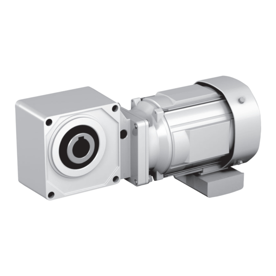
COMMON 1.Inspection Upon Delivery 1. Inspection Upon Delivery CAUTION G Unpack the unit after verifying that it is positioned right side up; otherwise, injury may result. G Verify that the unit received is in fact the one you ordered. Installing the wrong unit may result in personal injury or equipment damage. - Page 5 COMMON 1.Inspection Upon Delivery 1–2) Lubrication Method COMMON All models of Hyponic drives, are grease-lubricated. They are grease-packed when shipped from our factory and arrive ready to operate. 1–3) Nomenclature of Gearmotor Respective codes and Hyponic nomenclature are shown below. Please verify that the type of gearmotor you received conforms to what you ordered.
- Page 6 1.Inspection Upon Delivery 1–4) Spec cord of Gearmotor Respective codes and motor nomenclature are shown below. Please verify that the gearmotor type you received conforms to what you ordered. Notes : Because the spec cord is displayed when the customer directs it, it mighe not be writen in the rating plate and statemen of delivery.
- Page 7 COMMON 1.Inspection Upon Delivery 1–5) Type of Motor Respective codes and motor nomenclature are shown below. Please verify that the gearmotor type you received conforms to what you ordered. Product Standards • Regulations Single phase IEC Efficiency Standards Blank Three phase Blank Other types of motors Driving power Type of casing...
-
Page 8: Storage
COMMON 2.Storage 3.Transport 2. Storage When storing Hyponic drives for any extended period of time, consider the following important points: 2–1) Storage Location Store the unit in a clean, dry place indoors. · Avoid storage outdoors or in places with humidity, dust, sudden temperature changes or corrosive gas. -
Page 9: Installation
COMMON 4. Installation 4. Installation DANGER G Do not use a standard unit in an explosive atmosphere (which is likely to be filled with explosive gas or steam). Under such conditions, an explosion-proof motor should be used; otherwise, electric shock, personal injury, fire, explosion, or damage to the equipment may result. - Page 10 COMMON 4. Installation · Units made to special specifications are necessary for installation under conditions other than the above. · Units made according to the outdoor, explosion-proof or other specifications can be used under the specified conditions without any problem. ·...
- Page 11 COMMON 4. Installation Fig.2 Jig a………Spacer c………Nut b………Thrust Bearing d………Bolt The hollow shaft is made according to the tolerances of JIS H8. If you experience impact or notice a large radial load with the hollow shaft, further tighten the fitting between the hollow shaft and the driven shaft.
- Page 12 COMMON 4. Installation (c–1) How to set a torque arm (03#, 07#, 17#, 1010#) Mount a torque arm on the driven machine side of the Drive casing. Use hexagon socket head bolts for mounting. (See Table 3 for bolt sizes.) Torque arm anti-rotation stopper should be designed so as to allow movement of the torque arm to make sure that the contact surface between the Drive and shaft are free from excess force.
- Page 13 COMMON 4. Installation (a–2) How to set the shaft (1110#-1640#) Apply molybdenum disulfide grease to the surface of a driven shaft and the inner surface of a hollow shaft. Then insert the Drive into the driven shaft. If the fitting is too tight, lightly knock the end face of a hollow output shaft with a wooden hammer for smooth insertion.
- Page 14 COMMON 4. Installation Method to avoid the drive from slipping reactor to a driven machine (Fig.13–15) Stopper ring End plate Setting bolt Spacer Set screw Fig.13 Fixed by stopping shaft Fig.14 Fixed by spacer Fig.15 Fixed by set screw (c–2) How to set a torque arm (1110#-1640#) Mount a torque arm on the driven machine side of the Drive casing.
- Page 15 When installing the Drive, pay attention to the alignment between the Drive and shaft to be driven so that the Drive is free from excess force. Bearing unit Bearing unit HYPONIC DRIVE HYPONIC DRIVE hollow shaft type hollow shaft type...
-
Page 16: Coupling With Other Machines
COMMON 5. Coupling with Other Machines 5. Coupling with Other Machines CAUTION G Confirm the rotation direction before coupling the unit with the driven machine. Incorrect rotation direction may cause personal injury or damage to the equipment. G When operating the gearmotor alone (uncoupled), remove the key that is temporarily attached to the output shaft;... - Page 17 COMMON 5. Coupling with Other Machines 5–1) Confirming Rotation Direction Figure 19–21 shows the rotation direction of the output shaft when wires are connected as shown in Fig. 28–32 on page24–34. Fig.19 Rotation direction of slow speed shaft (RNYM Series) Frame size Reduction ratio 03#,07#...
- Page 18 COMMON 5. Coupling with Other Machines Fig.20 Rotation direction of slow speed shaft (RNFM Series) Frame size Reduction ratio 01#,03#,05#,07# 5, 80, 100, 120, 160, 200, 240 7.5, 10, 12, 15, 20, 25, 30, 40, 50, 60 15#,17# 5, 7.5, 10, 12, 80, 100, 120, 150, 200, 240 15, 20, 25, 30, 40, 50, 60 190# 7.5, 10, 15, 20, 30, 40, 50, 60 10, 15, 20, 25, 30, 40, 50, 60 80, 100, 120 10, 15, 20, 25, 30 40, 50, 60 150, 200, 240 270# 5, 7.5, 10, 15, 20 80, 100, 120 10, 15, 20, 25, 30 40, 50, 60 150, 200, 240 370# 5, 7.5, 10, 15, 20 80, 100, 120 10, 15, 20, 25, 30 40, 50, 60 150, 200, 240 470#...
- Page 19 COMMON 5. Coupling with Other Machines Fig.21 Rotation direction of slow speed shaft (RNHM Series) Frame size Reduction ratio 190# 7.5, 10, 15, 20, 30, 40, 50, 60 10, 15, 20, 25, 30, 40, 50, 60 80, 100, 120 10, 15, 20, 25, 30 40, 50, 60 150, 200, 240 270# 5, 7.5, 10, 15, 20 80, 100, 120 10, 15, 20, 25, 30 40, 50, 60 150, 200, 240 370# 5, 7.5, 10, 15, 20 80, 100, 120 10, 12, 15, 20, 25, 30 40, 50, 60 150, 200, 240 470# 5, 7.5, 10, 15, 20 80, 100, 120 53#,54# 10, 15, 20, 30 40, 50, 60, 80 150, 200, 240...
- Page 20 COMMON 5. Coupling with Other Machines 5–2) Coupling Installation · When installing a coupling, do not impact or apply excessive Connecting Shaft device thrust load to the shaft; otherwise, the bearing may be damaged. · Thermal shrinking or end cap screws are recommended for mounting (Fig.22).
-
Page 21: Wiring
COMMON 6. Wiring 6. Wiring I Wiring for SUMITOMO standard motor is shown below. Refer to the respective instruction manual when using another manufacturer,s motor. DANGER G Do not handle the unit when cables are live. Be sure to turn off the power; otherwise, electric shock may result. - Page 22 COMMON 6. Wiring CAUTION G When wiring, follow the facility s electrical codes and extension regulations; otherwise, burning, electric shock, injury, or fire may result. G The motor is not equipped with a protective device. However, it is compulsory to install an overload protector according to facility electrical codes.
- Page 23 COMMON 6. Wiring · Long cables cause voltage to drop. Select cables with appropriate diameter so that the voltage drop will be less than 2%. · After wiring outdoor and explosion-proof type motors , check that terminal box mounting bolts are not loose, and correctly attach the terminal box cover. 6–1) Attaching/Detaching The Terminal Box Cover (1) Detaching As shown in Fig.
- Page 24 COMMON 6. Wiring 6–3) Protection Coordination (1) Use a molded case circuit breaker for protection against short circuit. (2) Use an overload protection device that protects the unit against asurge of electric current exceeding that shown on the rating plate. (3) For an explosion-proof type motor , use an overload protector that can protect the unit...
- Page 25 6. Wiring 6–5) Motor (without brake) Connection Fig.28 shows the 3-phase motor, 3-phase high efficiency motor, 3-phase inverter motor (without brake) connection and the standard specifications for terminal codes. Fig.28-a In a case of three lead wires 3-phase motor, 3-phase high efficiency motor 3-phase inverter motor 15 –...
- Page 26 6. Wiring Fig.29 shows the Single-phase motor, Single-phase reversible motor (without brake) connection and the standard specifications. Fig.29-a In a case of capacitor run type 15W-90W 100V Class 200V Class White Black Blue White Black Brown Motor Motor Turn the switch SW to change the current to the opposite direction. (When instant switching is required, use a reversible motor.) MC: Electromagnetic contactor These should be OLR: Overload relay or...
- Page 27 6. Wiring Fig.29-b In a case of capacitor start and capacitor-run type 0.1kW-0.4kW 100V Class 200V Class Motor Motor Motor These should be MC: Electromagnetic contactor furnished by the OLR: Overload relay or thermal relay customer. Rotation shifting switch · Connection to Z1 and Z2 shall be exchanged with each other when reverse rotation is necessary if the motor is provided only for rotation in one direction.
- Page 28 6. Wiring 6–6) Motor with brake Connection Fig.30 shows the 3-phase motor, 3-phase high efficiency motor with brake connection and the standard specifications for terminal codes. Fig.30-a For operating in one directions (In a case of three lead wires) Brake type : SB-004 Brake type : MB-003-005 Rectifier 1 2 4...
- Page 29 6. Wiring Fig.30-b For operating in one directions (In a case of six lead wires) Brake type : FB-15B1 Brake type : FB-15B1 ―△ Connection Direct Starting Star (Wye)-Delta R S T △ 1 2 3 4 1 2 3 4 V1 W1 V2 W2 U2 Motor Rectifier...
- Page 30 6. Wiring Fig.30-c For operating in both directions (In a case of three lead wires) Brake type : SB-004 Brake type : MB-003-005 Rectifier 1 2 4 Red White Black Yel l o w Yel l o w Red White Black Yel l o w Yel l o w Motor Brake...
- Page 31 6. Wiring Fig.30-d For operating in both directions (In a case of six lead wires) Brake type : FB-15B1 Brake type : FB-15B1 ―△) Connection Direct Starting Star (Wye)-Delta ( R S T △ 1 2 3 4 1 2 3 4 V1 W1 V2 W2 U2 Motor Rectifier...
- Page 32 6. Wiring Fig.31 shows the Inverter motor with brake connection and the standard specifications for terminal codes. Fig.31-a For inverter driven (In a case of three lead wires) Brake type : Brake type : FB-1D-10B1 FB-02A1-05A1 Inverter Inverter 1 2 3 4 Motor Rectifier Brake Motor Rectifier Brake...
- Page 33 6. Wiring Fig.32 shows the Single-phase motor with brake connection and the standard specifications. Fig.32-a-1 For operating in one directions (In a case of capacitor run type 15W-90W) Brake type : SB-004 100V 200V Rectifier Rectifier 1 2 4 1 2 4 White Black Brown Yellow Yellow White...
- Page 34 6. Wiring Fig.32-a-2 For operating in one directions (In a case of capacitor start and capacitor-run type 0.1kW-0.4kW) Brake type : FB-01A1-02A1 100V 200V Brake Rectifier Brake Rectifier Motor Motor Brake Brake Rectifier Rectifier Motor Motor Brake type : FB-1D 100V 200V Note : Connection to Z1 and Z2 shall be...
- Page 35 6. Wiring Fig.32-b-1 For operating in both directions (In a case of capacitor start and capacitor-run type 0.1kW-0.4kW) Brake type : FB-01A1-02A1 100V 200V Control panel Control panel 1 2 4 1 2 4 Rectifier Brake Rectifier Brake Motor Motor Terminal box Terminal box Control panel Control panel 1 2 4 1 2 4 Rectifier Brake Rectifier Brake Motor Motor...
- Page 36 6. Wiring Table 9 Varistor (VR) Capacity Input power AC200V–230V AC380V–460V Rated voltage of varistor AC260V–AC300V AC510V Voltage of varistor 430V–470V 820V SB-004, FB-01A1, 02A1, 0.25Watt or more 0.4Watt or more 05A1 Rated power Brake type FB-1D 0.4Watt or more 0.6Watt or more of varistor FB-2D, 3D, 5B, 8B...
-
Page 37: Operation
COMMON 7. Operation 7. Operation DANGER G Do not approach or touch rotating parts (output shaft, etc.) during operation; loose clothing may become caught in these rotating parts and cause serious injury or death. G When the power supply is interrupted, be sure to turn off the power switch. Unexpected resumption of power may cause electric shock, personal injury, or damage to the equipment. - Page 38 COMMON 7. Operation Table 10 Items to check during initial start - up and break - in period (1) Is the housing deformed because the installation surface is not flat ? Is abnormal (2) Is insufficient rigidity of the installation base generating excessive noise ? sound or (3) Is the shaft center aligned with the driven machine ? vibration generated ?
-
Page 39: Daily Inspection And Maintenance
COMMON 8. Daily Inspection and Maintenance 8. Daily Inspection and Maintenance DANGER G Do not handle the unit when cables are live. Be sure to turn off the power; otherwise, electric shock may result. G Do not approach or touch any rotating parts (output shaft, etc.) during maintenance or inspection of the unit;... - Page 40 COMMON 8. Daily Inspection and Maintenance To ensure proper and continued optimum operation, use Table 11 to perform daily inspections. Table 11 Daily Inspection Inspection item Details of inspection Is the current below the rated current shown on the rating plate ? Electric current Noise Is there abnormal sound ? Is there sudden change in sound ?
-
Page 41: Brake Maintenance
9. Brake Maintenance 9. Brake Maintenance I This section discusses the operation and maintenance of the sumitomo brake . (When using another manufacturer s brake , please refer to their maintenance manual.) I Refer to Brake operation manual (Cat.No.MM0202E) for FB-01A1, 02A1, 05A1, 1D, 2D, 3D, 5B, 8B,10B1 and 15B1 outdoor type. - Page 42 9. Brake Maintenance 9–1) Construction and Operation Figs. 33–42 show the construction of the brake. A spring is used for braking operation (nonexcitation operation type). Part name Brake restraining bolt Stationary Armature plate Lining with fan Setting bolt Retaning ring Cover Torque spring Fig.33...
- Page 43 9. Brake Maintenance Part name Brake lining Armature plate Rectifier Leaf spring Torque spring Stationary Fan set bolt Cover Fan (provided for single-phase 60,90W) Boss Boss setting bolt Brake restraining bolt Fixed plate Fig.35 MB-003, 005 Part name Brake lining Armature plate Cover Leaf spring...
- Page 44 9. Brake Maintenance Part name Stationary core 10 9 Release fitting Manual release prevention spacer Brake release bolt Spacer Gap adjusting shim Assembly bolt Brake lining Leaf spring Boss Shaft retaining C-ring Fan set bolt Cover Fixed plate Armature plate Spring Electromagnetic coil 19 20...
- Page 45 9. Brake Maintenance Part name Stationary core Release fitting Stud bolt Adjusting washer Manual release prevention spacer Brake release bolt Spring washer Gap adjusting nut Brake lining Boss Shaft retaining C-ring Cover Spring pin Leaf spring Fixed plate Armature core Spring Electromagnetic coil 19 20...
- Page 46 9. Brake Maintenance Part name Stationary core 11 10 Release fitting Stud bolt Adjusting washer Manual release prevention spacer Brake release bolt Spring washer Gap adjusting nut Brake lining Boss Shaft retaining C-ring Cover Fan set bolt Leaf spring Fixed plate Armature core Spring Electromagnetic coil...
- Page 47 9. Brake Maintenance 9–2) Manual Release Operation of Brake (FB-1D–15B1, FB-01A1–05A1 are options.) To manually release the brake without turning on the power, operate the brake release device as follows: (1) Remove the brake release bolts arranged diagonal to each other, and remove the spacer.
- Page 48 9. Brake Maintenance 9–4) Gap Adjustment When the gap nears the limit shown in Table 12 on page 39, follow these steps to, adjust the gap. (Gap of MB-003, 005 can not be adjusted.) [SB–004] (See Fig.33, 34 on page 41) (1) Remove cover 7.
- Page 49 9. Brake Maintenance [FB–2D] (See Fig.39 on page 43) (1) Remove assemble bolt 4 and manual release prevention spacer 3. (2) Remove cover !3 . (3) Remove fan set bolt !2 , and remove fan !4 . (4) Loosen assembly bolt 7, and remove spacer 5, gap adjusting shim 6, assembly bolt 7, and fixed plate !5 together as a set.
- Page 50 9. Brake Maintenance [FB–5B, 8B, 10B1 and 15B1] (See Fig.38 on page 41, Fig. 42 on page 45) (1) Remove assemble bolt 6 and manual release prevention spacer 5. (2) Remove cover !2 . (3) Insert the feeler gauge between stationary core 1 and armature core !7 , and turn clockwise the gap adjusting nut 8 attached to the end of stud bolt 3.
-
Page 51: Troubleshooting
COMMON 10. Troubleshooting 10. Troubleshooting · If any abnormality is found in the gearmotor, refer to Table 14 below and take appropriate measures as soon as possible. If the abnormality cannot be eliminated, contact our nearest agent, dealer or sales office. Table 14 Troubleshooting Type of Trouble Cause... - Page 52 COMMON 10. Troubleshooting Table 14 Troubleshooting Type of Trouble Cause Remedy Ooze of lubricating grease from Wipe up grease or replace an oil Ooze of grease from an oil an oil seal at an early stage of seal when grease leakage cannot seal.
-
Page 53: Construction Drawings
COMMON 11. Construction Drawings 11. Construction Drawings Fig.44 RNFM0025-03L-240 Fig.45 RNYM0025-03-240 Part name Part name Part name Hypoid gear Gear Rotor core Output shaft Pinion shaft Rotor conductor short circuit ring Oil seal Gear Stator windings Casing Pinion shaft End bracket Cover Hypoid pinion shaft Bearing metal... - Page 54 COMMON 11. Construction Drawings Fig.46 RNFM1-50R-120 Fig.47 RNYM1-1530-120 Part name Part name Part name Hypoid gear Gear Rotor conductor short circuit ring Output shaft Pinion shaft Oil seal Hypoid pinion shaft Fan cover Case (1) Motor frame End bracket Case (2) Stationary core Bearing metal Gear...
-
Page 55: Warranty
COMMON 12. Warranty 12. Warranty The scope of our warranty for our products is limited to the range of our manufacture. Warranty (period and contents ) The warranty period for the Products shall be 18 months after the commencement of Warranty delivery or 18 months after the shipment of the Products from the seller,s works or 12 Period... - Page 56 Worldwide Locations U.S.A France Singapore Sumitomo Machinery Corporation of America SM-Cyclo France SAS (SMFR) Sumitomo (SHI) Cyclo Drive Asia Pacific Pte. (SMA) Ltd. (SCA) 8 Avenue Christian Doppler, 77700 Serris, France 4200 Holland Blvd. Chesapeake,VA 23323,U.S.A. 15 Kwong Min Road, Singapore 628718 TEL (33)164171717 FAX (33)164171718 TEL (65)6591-7800...
Need help?
Do you have a question about the HYPONIC DRIVE and is the answer not in the manual?
Questions and answers