
Related Manuals for Aaeon AGD-315D


Summary of Contents for Aaeon AGD-315D
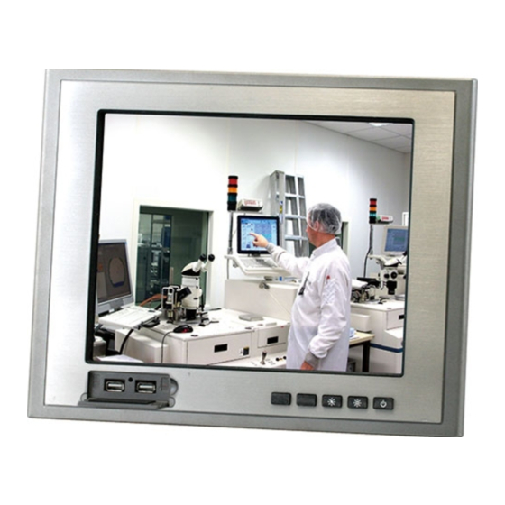
- Page 1 L C D D i s p l a y A G D - 3 1 5 D AGD-315D 15” XGA Rugged Touch Display On Screen Display Control IP-65 Front Bezel 5-wire Resistive Touch Screen AGD-315D Manual 2 June 22, 2015...
- Page 2 AAEON, assumes no liabilities resulting from errors or omissions in this document, or from the use of the information contained herein. AAEON reserves the right to make changes in the product design without notice to its users.
- Page 3 L C D D i s p l a y A G D - 3 1 5 D Acknowledgments ® ® Intel is registered trademarks of Intel Corporation. IBM, PC/AT, PS/2 are trademarks of International Business Machines Corporation. ®...
- Page 4 The LCD monitor comes with the following standard parts shown as below. Check and make sure they are included and in good condition. If anything is missing or damaged, contact the dealer immediately. AGD-315D Utility CD-ROM Contains User’s Manual (in PDF format), Drivers and Utilities ...
- Page 5 L C D D i s p l a y A G D - 3 1 5 D Safety & Warranty 1. Read these safety instructions carefully. 2. Keep this user's manual for later reference. 3. Disconnect this equipment from any AC outlet before cleaning. Do not use liquid or spray detergents for cleaning.
- Page 6 L C D D i s p l a y A G D - 3 1 5 D 14. If any of the following situations arises, get the equipment checked by service personnel: a. The power cord or plug is damaged. b.
- Page 7 L C D D i s p l a y A G D - 3 1 5 D Below Table for China RoHS Requirements 产品中有毒有害物质或元素名称及含量 AAEON Display 有毒有害物质或元素 部件名称 铅 汞 镉 六价铬 多溴联苯 多溴二苯醚 (Pb) (Hg) (Cd) (Cr(VI)) (PBB) (PBDE) 印刷电路板...
-
Page 8: Table Of Contents
L C D D i s p l a y A G D - 3 1 5 D Contents Chapter 1 General Information 1.1 Introduction ..............1-2 1.2 Features ..............1-3 1.3 General Specification ..........1-4 1.4 Dimension ..............1-6 1.5 Waterproof Sponge Position ........ - Page 9 L C D D i s p l a y A G D - 3 1 5 D 3.4 Contrast/ Brightness- Submenu........ 3-5 3.5 Geometry Menu............3-6 3.6 Color Temperature- Submenu OSD Main Menu: Push The MENU Keys.............. 3-7 3.7 RGB Color- Submenu.
-
Page 10: Chapter 1 General Information
L C D D i s p l a y A G D - 3 1 5 D Chapter General Information Chapter 1 General Information... -
Page 11: Introduction
Users may refer to the AAEON.com for the latest version of this document. Chapter 1 General Information... -
Page 12: Features
L C D D i s p l a y A G D - 3 1 5 D 1.2 Features 15” XGA (1024 x 768) TFT LCD Display Wide Temperature Operation (0 ~ 55°C) Front USB Ports for Easy Access ... -
Page 13: General Specification
OSD (On Screen Display) on the front cover Control Power Supply External power adapter Dimension AGD-315D 15.35” (W) x 12.74”(H) x 4.91”(D) (390mm x 323.5mm x 124.7mm) Cutout Size 14.8”(W) x 12.03”(H) (376mm x 305.5mm) 9 lb (4.1 Kg) ... - Page 14 L C D D i s p l a y A G D - 3 1 5 D 2048 x 2048 Resolution 88 ± 2% (Pure) Light transmission RS-232 & USB interface (optional) Controller Environmental 32°F~ 131°F (0°C to 55°C) Operating temperature ...
-
Page 15: Dimension
L C D D i s p l a y A G D - 3 1 5 D 1.4 Dimension Chapter 1 General Information... - Page 16 L C D D i s p l a y A G D - 3 1 5 D Chapter 1 General Information...
-
Page 17: Waterproof Sponge Position
L C D D i s p l a y A G D - 3 1 5 D 1.5 Waterproof Sponge Position Inside sponge: Tear off the protection paper on the self-adhesive side of the inside sponge. Stick the sponge on the recessed area of the Aluminum bezel or customer’s own bezel. -
Page 18: Chapter 2 Hardware Installation
L C D D i s p l a y A G D - 3 1 5 D Chapter Hardware Installation Chapter 2 Hardware Installation... -
Page 19: Before Unpacking
L C D D i s p l a y A G D - 3 1 5 D 2.1 Before Unpacking It is very important to place the LCD Display in a suitable environment. The surface for placing the LCD Display should be stable and level. -
Page 20: Connecting Power
L C D D i s p l a y A G D - 3 1 5 D 2.2 Connecting Power To power on the LCD Display, use the provided AC-DC adapter and the power cord to connect to the power output socket of the monitor. Fasten the connector securely. -
Page 21: Connecting To The Computer
L C D D i s p l a y A G D - 3 1 5 D 2.3 Connecting to the Computer Turn off the computer and the LCD Display before connecting. Use the Monitor-to-PC VGA、DVI cable to connect the LCD Display to your computer. -
Page 22: Vga Port Connector
L C D D i s p l a y A G D - 3 1 5 D 2.4 VGA Port Connector This DB-15 connector can be connected to the system via the external 15-pin DB-15 connector through the I/O from this unit. Signal Signal Green... -
Page 23: Dvi Port Connector
L C D D i s p l a y A G D - 3 1 5 D 2.5 DVI Port Connector Connecting a standard DVI-D connector through I/O port of this unit. This connector supports digital signals only Signal Signal N.C. -
Page 24: Serial Port Connector For Touch Screen
L C D D i s p l a y A G D - 3 1 5 D 2.6 Serial Port Connector For Touch Screen This pin definition of the connector will be referred when a touch screen has been installed. It must be connected to the RS-232 port of the PC. -
Page 25: Mini Usb Connector For Touch Screen
L C D D i s p l a y A G D - 3 1 5 D 2.7 Mini USB Connector For Touch Screen This pin definition of the connector will be referred when a touch screen has been installed. It must be connected to the Mini USB port of the PC. -
Page 26: Panel Mounting
L C D D i s p l a y A G D - 3 1 5 D 2.8 Panel Mounting To mount the panel onto a wall, you will need screws along the mounting brackets, which are packed in the accessory box. Follow the steps below: Step 1: Insert the screw through the mounting bracket. - Page 27 L C D D i s p l a y A G D - 3 1 5 D Complete Illustration 2-10 Chapter 2 Hardware Installation...
-
Page 28: Easy Stand, Swing-Arm Mounting
Easy Stand The brackets of easy stand are attached to the rear of AGD-315D. First of all, loosen the screw of point A. Then, unscrew the screw of point B. Pull down the bracket and use the screw got from point A to fasten the bracket in point B. -
Page 29: Vesa Wall Mounting
L C D D i s p l a y A G D - 3 1 5 D 2.10 VESA Wall Mounting Mounting the LCD Display with UL Listed Wallmount Bracket only. The LCD Display can be mounted on a monitor arm or wallmount plate. - Page 30 L C D D i s p l a y A G D - 3 1 5 D VESA Mounting Holes To mount the LCD Display onto a monitor arm or wallmount plate, please follow the steps below. Step 1: Line up the threaded holes on the monitor rear panel with the screw holes on the monitor arm or wallmount plate.
-
Page 31: Chapter 3 On Screen Display Control
L C D D i s p l a y A G D - 3 1 5 D Chapter On Screen Display Control Chapter 3 On Screen Display Control 3-1... -
Page 32: On Screen Display (Osd) Board Description
L C D D i s p l a y A G D - 3 1 5 D 3.1 On Screen Display (OSD) Board Description Buttons Description Power Turn the monitor power ON or OFF. Activate the OSD menu. Menu / Enter ... -
Page 33: Osd Main Menu: Push The Menu Keys
L C D D i s p l a y A G D - 3 1 5 D 3.2 OSD Main Menu: Push The MENU Keys Available Key Functions Power On/Off the LCD Monitor Return to last menu Selected to confirm Increase the gauge value of the selected option Decrease the gauge value of the selected option Chapter 3 AMI BIOS Setup 3-3... -
Page 34: Select Input Source
L C D D i s p l a y A G D - 3 1 5 D 3.3 Select Input Source • Available Key Functions Power On/Off the LCD Monitor Return to last menu Selected to confirm Increase the gauge value of the selected option Decrease the gauge value of the selected option Chapter 3 On Screen Display Control 3-4... -
Page 35: Contrast/ Brightness- Submenu
L C D D i s p l a y A G D - 3 1 5 D 3.4 Contrast/ Brightness- Submenu Available Key Functions Power On/Off the LCD Monitor Return to last menu Selected to confirm Increase the gauge value of the selected option Decrease the gauge value of the selected option Chapter 3 AMI BIOS Setup 3-5... -
Page 36: Geometry Menu
L C D D i s p l a y A G D - 3 1 5 D 3.5 Geometry Menu Available Key Functions Power On/Off the LCD Monitor Return to last menu Selected to confirm Increase the gauge value of the selected option Decrease the gauge value of the selected option Chapter 3 On Screen Display Control 3-6... - Page 37 L C D D i s p l a y A G D - 3 1 5 D 3.6 Color Temperature- Submenu Available Key Functions Power On/Off the LCD Monitor Return to last menu Selected to confirm Increase the gauge value of the selected option Decrease the gauge value of the selected option Chapter 3 AMI BIOS Setup 3-7...
-
Page 38: Rgb Color- Submenu
L C D D i s p l a y A G D - 3 1 5 D 3.7 RGB Color- Submenu Available Key Functions Power On/Off the LCD Monitor Return to last menu Selected to confirm Increase the gauge value of the selected option Decrease the gauge value of the selected option Chapter 3 On Screen Display Control 3-8... -
Page 39: Language- Submenu
L C D D i s p l a y A G D - 3 1 5 D 3.8 Language- Submenu Available Key Functions Power On/Off the LCD Monitor Return to last menu Selected to confirm Increase the gauge value of the selected option Decrease the gauge value of the selected option Chapter 3 AMI BIOS Setup 3-9... -
Page 40: Auto Config- Submenu
L C D D i s p l a y A G D - 3 1 5 D 3.9 Auto Config- Submenu Available Key Functions Power On/Off the LCD Monitor Return to last menu Selected to confirm Increase the gauge value of the selected option Decrease the gauge value of the selected option Chapter 3 On Screen Display Control 3-10... -
Page 41: Mode Resolution- Submenu Chapter
L C D D i s p l a y A G D - 3 1 5 D 3.10 Mode Resolution- Submenu Available Key Functions Power On/Off the LCD Monitor Return to last menu Selected to confirm Increase the gauge value of the selected option Decrease the gauge value of the selected option Chapter 3 AMI BIOS Setup 3-11... -
Page 42: Exit Menu- Submenu
L C D D i s p l a y A G D - 3 1 5 D 3.11 Exit Menu- Submenu Available Key Functions Power On/Off the LCD Monitor Return to last menu Selected to confirm Increase the gauge value of the selected option Decrease the gauge value of the selected option Chapter 3 On Screen Display Control 3-12... -
Page 43: Chapter 4 Touch Screen Driver Installation
L C D D i s p l a y A G D - 3 1 5 D Chapter Touch Screen Driver Installation Chapter 4 Touch Screen Driver Installation... -
Page 44: Introduction
L C D D i s p l a y A G D - 3 1 5 D 4.1 Introduction The optional AGD-315D Series touch screen uses 5-wire resistive technology to provide more accurate sensing capacity than other technologies. The touch screen is specially designed for tough industrial environments, and has been approved by FCC Class A standards. - Page 45 L C D D i s p l a y A G D - 3 1 5 D Serial Interface • EIA 232E (Serial RS-232), DCE configuration. 8 Data Bits, 1 Stop Bit, No Parity, Full Duplex. • Hardware handshaking: RTS/CTS. •...
- Page 46 L C D D i s p l a y A G D - 3 1 5 D Operating Modes Full Touch Smart Set protocol. Emulation of E281A-4002 protocol can be selected by Smart Set command. Initial/ Stream/ Un touch/ Z-axis Enable Modes. Touch Resolution: 2048 x 2048, size independent.
-
Page 47: Resistive Touch Screen Driver Installation
L C D D i s p l a y A G D - 3 1 5 D 4.2 Resistive Touch screen Driver Installation Hardware Touch screen controllers must be configured for the driver prior to installation. EETI typically ships controllers in a default setup that is compatible with this driver. - Page 48 L C D D i s p l a y A G D - 3 1 5 D HID drivers that provide low-level support for EETI touch screen controller. An EETI touch monitor with a USB touch screen controller installed will provide the following limited operation with these native HID drivers.
-
Page 49: Installing Driver For Windows
L C D D i s p l a y A G D - 3 1 5 D ® ® 4.3 Installing Driver for Windows XP/ Windows 7 / Linux ® ® The touch screen has drivers for Windows XP、 Windows 7 and Linux . - Page 50 L C D D i s p l a y A G D - 3 1 5 D 2. Click the “Next” button on the screen 3. Click on the “Finish” button and restart your system Single monitor, Serial Port controller The driver files will install automatically.
- Page 51 L C D D i s p l a y A G D - 3 1 5 D 1. Executing eGalax on Desktop 2. Recognition devices choose to run calibration immediately Chapter 4 Driver Installation...
- Page 52 L C D D i s p l a y A G D - 3 1 5 D 3. Choose Tools to calibrate 4. Click on 4 Points Calibration to execute calibration Note: If the alignments do not match display by 4 Points Calibration, please use 9 Ports or more to calibrate.
- Page 53 L C D D i s p l a y A G D - 3 1 5 D ® For Windows 7 OS please execute: CD-ROM: \\TouchScreen-DRV\eGalax Touch \Win 7 \Setup.exe 1. Click on the “Next” button 2. Click on the “Next” button 4-11 Chapter 4 Driver Installation...
- Page 54 L C D D i s p l a y A G D - 3 1 5 D 3. Tick “None” if the system did not start 4 points calibrating after reboot. Click on the “Next” button. 4. Tick “Support Multi-Monitor System,” and click on the “Next” button 4-12 Chapter 4 Touch Screen Driver Installation...
- Page 55 L C D D i s p l a y A G D - 3 1 5 D 5. Select Destination Folder, and click on the “Next” button 6. Click on the “Next” button Single monitor, Serial Port controller The driver files will install automatically. When the "Setup Complete"...
- Page 56 L C D D i s p l a y A G D - 3 1 5 D 1. Executing eGalax on Desktop 2. Recognition devices choose to run calibration immediately 4-14 Chapter 4 Touch Screen Driver Installation...
- Page 57 L C D D i s p l a y A G D - 3 1 5 D 3. Choose Tools to run calibration 4. Click on 4 Points Calibration to execute calibration Note: If the alignments do not match display by 4 Points Calibration, please use 9 Ports or more to calibrate.
- Page 58 L C D D i s p l a y A G D - 3 1 5 D For Linux Fedora 14 kernel 2.6.35.6-45.fc14 OS please execute: CD-ROM: \\TouchScreen-DRV\eGalax Touch \Linux\eGalaxTouch 32 1. Open System Input Command (su) and System Password 2.
- Page 59 L C D D i s p l a y A G D - 3 1 5 D 3. Input command ( cp /root/xorg.conf.new /etc/X11/xorg.conf) 4. Load Linux Folder Touch Driver 4-17 Chapter 4 Driver Installation...
- Page 60 L C D D i s p l a y A G D - 3 1 5 D 5. Executive Touch Driver 6. Which interface controller do you use? 4-18 Chapter 4 Touch Screen Driver Installation...
- Page 61 L C D D i s p l a y A G D - 3 1 5 D 7. Select the “ 3 ” USB interface. (Select the USB interface and press “Enter” key of the keyboard to start the installation) 8.
- Page 62 L C D D i s p l a y A G D - 3 1 5 D 9. Reboot the system to activate the changes 10. Select the X86 Folder (Because Linux is 32 bit) 4-20 Chapter 4 Touch Screen Driver Installation...
- Page 63 L C D D i s p l a y A G D - 3 1 5 D 11. Select “eGalax Touch32_Version1.1-2.6X” Folder 12. Select “eGalax Touch32” Folder 4-21 Chapter 4 Driver Installation...
- Page 64 L C D D i s p l a y A G D - 3 1 5 D 13. Click on the “eGalax Touch” to calibrate immediately 14. Choose “Tool” to calibrate 4-22 Chapter 4 Touch Screen Driver Installation...
- Page 65 L C D D i s p l a y A G D - 3 1 5 D 15. Execute 4 Points Calibration Note: If the alignments do not match display by 4 Points Calibration, please use 9 Ports or more to calibrate. 16.
- Page 66 L C D D i s p l a y A G D - 3 1 5 D 17. If you are going to replace the Interface, please remove the old Touch Driver (Input command: sh setup.sh uninstall) 18. Reboot the system 4-24 Chapter 4 Touch Screen Driver Installation...
Need help?
Do you have a question about the AGD-315D and is the answer not in the manual?
Questions and answers