
Related Manuals for A.H. Systems AK-18G


Summary of Contents for A.H. Systems AK-18G
- Page 1 A.H. Systems AK-18G Antenna Kit AK-18G Antenna Kit Operation Manual © A.H. Systems inc. – May 2014 REV C...
-
Page 2: Table Of Contents
A.H. Systems AK-18G Antenna Kit TABLE OF CONTENTS WARRANTY INTRODUCTION GENERAL INFORMATION OPTIONAL EQUIPMENT FORMULAS MAINTENANCE © A.H. Systems inc. – May 2014 REV C... -
Page 3: Warranty
A.H. Systems AK-18G Antenna Kit WARRANTY INFORMATION A.H. Systems Inc., warrants that our Antennas, Sensors and Probes will be free from defects in materials and workmanship for a period of three (3) years. All other products delivered under contract will be warranted for a period of two (2) years. Damage caused by excessive signals at the product's input is not covered under the warranty. -
Page 4: Introduction
Up to 18 GHz 3.5 dB @ 18 GHz OPTIONAL EQUIPMENT Gain / Attenuation 20 MHz – 18 GHz PAM-0118 33 dB SAC-18G-0.5 Up to 18 GHz 1.5 dB @ 18 GHz © A.H. Systems inc. – May 2014 REV C... -
Page 5: General Information
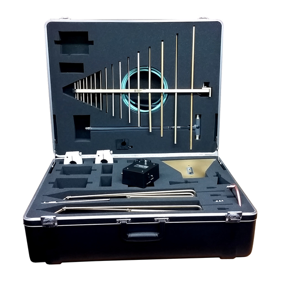
GENERAL DESCRIPTION The A.H. Systems AK-18G antenna kit series consist of five E-field antennas, one magnetic loop antenna, and two current probes. Each of the antennas and probes are provided with calibrations when connected to a 50-ohm input receiver or spectrum analyzer. - Page 6 EUT to measure magnetic radiation. Connect the antenna via a cable to a receiver with either a 50 ohm input or high impedance (10 K ohm or greater) input. Calibrations for both inputs are provided. © A.H. Systems inc. – May 2014 REV C...
-
Page 7: Optional Equipment
The preamplifier will increase the system sensitivity 37 dB and is recommend for the SAS-510-2, SAS-530,542 and SAS-571. An optional short length cable (SAC- 18G-0.5), is required to connect the preamplifier to any 50-ohm receiver or spectrum analyzer. © A.H. Systems inc. – May 2014 REV C... - Page 8 VSWR, and high frequency capabilities, the Low- Loss cables can be made to your specified length and delivered in two days. The 1/2 meter SAC-18G-0.5 has a typical attenuation of 1.0 dB at 18GHz. © A.H. Systems inc. – May 2014 REV C...
-
Page 9: Formulas
Transfer Impedance: -2.76 dB ohms Cable Loss: 0.1dB Receiver Reading: -33.0dBuV dBA = dBV (from Receiver) - Transfer Impedance (dB) - cable Loss (dB) dBA = -33.0 (-2.76) - 0.1 dBA = -30.14 © A.H. Systems inc. – May 2014 REV C... -
Page 10: Maintenance
To ensure reliable and repeatable long-term performance, annual re-calibration of your antennas, preamplifiers and current probes by A.H. Systems experienced technicians is recommended. Our staff can calibrate almost any type or brand of antenna. For more information about our calibration services or to place an order for antenna calibration visit our website at http://www.AHSystems.com or call 1(818) 998-0223.
Need help?
Do you have a question about the AK-18G and is the answer not in the manual?
Questions and answers