Table of Contents
Advertisement
Quick Links
Advertisement
Table of Contents

Related Manuals for Funktion-one F1201


Summary of Contents for Funktion-one F1201
-
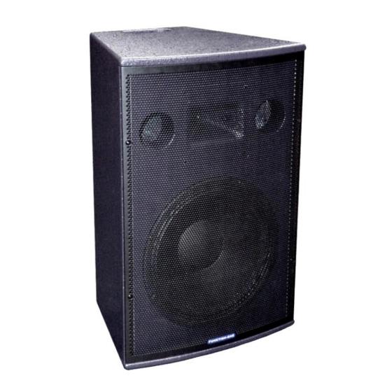
Page 1: F1201 User Guide
F1201 User Guide www.funktion-one.com © Funktion One Research Limited 2013... -
Page 2: Table Of Contents
Contents F1201 User Guide ..........................1 Thank you ..........................2 Receiving and unpacking ......................3 Handling ............................ 4 Introduction ..........................4 Features ............................... 4 Specifications ............................... 5 Safety first ..........................6 Mechanical safety ............................6 Electrical and fire safety ..........................7 Hearing safety .............................. -
Page 3: Receiving And Unpacking
We know that you’ll be eager to install your F1201 system and get it up and running immediately, but reading this user guide will help you to achieve the best performance - just as Funktion One intended. -
Page 4: Handling
The F1201 works as a stand-alone PA or for use in small clubs and bars, and is ideally suited for use with BR218, Infrabass 218 or F121 bass enclosures where low bass extension is needed. -
Page 5: Specifications
2 x M10 yoke mounting bushes (one per side) 9 x M10 top, bottom, side and rear bushes 4 x M8 wall bracket bushes Weight: 18kg (39lb) Dimensions Fig 4.2-1 F1201 dimensions (In millimetres and feet & inches) www.funktion-one.com © Funktion One Research Limited 2013... -
Page 6: Safety First
See section 6.3 Pole mounting Make sure your pole mount is compatible with the F1201’s 35mm pole socket and is a snug fit. Always check the stand manufacturer’s specifications Make sure that the pole mount stand will support the weight of the loudspeaker. Again, check the stand manufacturer’s specifications... -
Page 7: Electrical And Fire Safety
There are no user-serviceable parts inside your F1201 system. Do not dismantle the unit F1201’s are not designed for use in damp conditions and should not be exposed to water Hearing safety Enjoy your system responsibly Funktion One loudspeaker systems are designed to provide extensive audience coverage at low distortion and are capable of producing very high near-field sound pressure levels. -
Page 8: Coverage
Fig 6.1-1 On-axis vs 45° horizontal off-axis response The F1201 has been designed to work well as a stand-alone system without off-axis room colouration. Multiple F1201s may be splayed 30-45° axis-to-axis horizontally or 15-22° axis-to-axis vertically for wide coverage applications. The lower splay angle gives extra summation between the cabinets in each case. -
Page 9: Placement
Even if the room has good acoustical properties, your audience will enjoy far better sound quality if the system is aiming towards them. Mounting your F1201 systems 2.8 – 3.3m above the floor and aiming them towards head height about 2/3rds across the audience will provide smooth coverage without over-exciting the room. - Page 10 Multiple F1201s may be used to concentrate coverage into a specific area. This will provide audience members with a pleasant, enveloping experience. Minimising difficult room effects Fig 6.2-4 Raising and tilting F1201s for more concentrated central coverage in difficult acoustics www.funktion-one.com © Funktion One Research Limited 2013...
- Page 11 Horizontal aiming Stereo set-ups Fig 6.2-5 Poor horizontal aiming Avoid aiming your F1201 straight out as this can increase side wall effects and will cause coverage gaps in between the loudspeakers. Fig 6.2-6 Improved horizontal aiming Even if the room has good acoustical properties, your audience will enjoy far better sound quality if the system is toed in towards them rather than reflecting off the side walls.
- Page 12 The best way to ensure the widest possible stereo listening area is to aim your left and right F1201 systems, both horizontally and vertically, so that their on-axis lines cross over at ear height at approximately 2/3 the distance to the rear of the audience.
- Page 13 Multiple loudspeaker systems Where multiple loudspeakers are to be used to concentrate coverage into a specific area, your F1201’s 90° horizontal coverage allows simple four-corner set-ups for foreground music coverage. Fig 6.2-8 4-speaker set-up Generally speaking, every time you double the number of loudspeakers at equal distances from you, you’ll increase sound pressure level by between 3 and 6dB.
- Page 14 (Distance in metres from Main F1201 – Distance in metres from Delay F1201) x 2.91 Imperial: (Distance in feet from Main F1201 – Distance in feet from Delay F1201) x 0.887 (Hint: If you don’t have a calculator, the multipliers may be rounded to 3.0 for metric or 0.9 for imperial) ...
-
Page 15: Wall Mounting And Yoke Accessories
Wall bracket Fig 6.3-1 WME-100 wall mounting bracket (all dimensions in mm) The optional WME-100 wall mounting bracket allows your F1201 to be mounted on a wall and aimed accurately. and 2 The wall mounting plate may be removed and sent to site for pre-installation if required. - Page 16 The speaker mounting plate is attached to your F1201 with the M8 hex-head bolts, flat washers and spring washers provided.
- Page 17 (Side view) (View from above) Fig 6.3-6 Maximum tilt and swivel angles (F1201 mounted vertically) (Side view) (View from above) Fig 6.3-7 Maximum tilt and swivel angles (F1201 mounted horizontally) www.funktion-one.com...
- Page 18 YF1201 vertical yoke The optional YF1201-K1 vertical yoke kit allows you to fly your F1201 from a truss or 51mm barrel via a standard half-coupler using the main fixing hole. The yoke also has a 7mm safety wire attachment hole.
- Page 19 YF1201 vertical yoke dimensions (millimetres and feet & inches) YH1201 horizontal yoke A horizontal yoke kit is also available. It comes complete with pivot plates that bolt to the F1201’s “top” ° and “bottom” M10 mounting bushes. This yoke also has a 7mm safety point and allows for a full 360 enclosure rotation.
-
Page 20: Connectors And Pin-Outs
Your F1201’s rear NL4 connectors will accept either NL2 or NL4 connector types The following illustrations show the cable connector pin views looking towards the rear of the loudspeaker - as they would be seen if the cable plugs were plugged into the F1201 with their covers removed. -
Page 21: Loudspeaker Polarity
It is usually fairly easy to ensure that your loudspeakers are wired to the same polarity if all your loudspeakers are being driven via identical signal paths and equipment. Simply check that the same www.funktion-one.com © Funktion One Research Limited 2013... - Page 22 Common sense, then, suggests that, as long as we’re using polarity-matched microphones and well- documented signal paths, why not maintain absolute polarity – if only for consistency? www.funktion-one.com © Funktion One Research Limited 2013...
-
Page 23: Loudspeaker Cables
F1201 half-space, 1/3 octave impedance (ohms) vs frequency (Hz) The F1201 impedance curve presents an easy load for power amplifiers – even where pairs of F1201s are connected in parallel. Note that low frequency impedance characteristics may vary slightly with local boundary conditions www.funktion-one.com... -
Page 24: Amplifier Considerations
Recommended range = 350W - 1400W into 8Ω, 700W – 2800W into 4Ω or 1400W – 5600W into 2Ω Most amplifiers are rated into 8 ohms (1 x F1201) and 4 ohms (2 x F1201s in parallel) Amplifiers with a genuine 2 ohm specification can power up to 4 x F1201s in parallel – but remember to use thicker cable when connecting multiple loudspeakers in parallel. -
Page 25: Simple System Patches With External Control
2-channel 8 ohm patch using Funktion One E45 power amplifier Fig 9.3-2 2-channel 4 ohm patch using Funktion One E45 power amplifier 4-channel 8 ohm patches with external control Fig 9.3-3 4-channel 8 ohm patch using Funktion One F60Q power amplifier www.funktion-one.com © Funktion One Research Limited 2013... -
Page 26: Xo Series Loudspeaker Management Patches
2-channel 8 ohm patch using Funktion One XO2 controller and E45 amp (2 x 2-way + 2 x mono configuration shown) Fig 9.4-2 2-channel 4 ohm patch using Funktion One XO2 controller and E45 amp (2 x 2-way + 2 x mono configuration shown) www.funktion-one.com © Funktion One Research Limited 2013... - Page 27 (4 x 2-way configuration shown) 4-channel 4 ohm patches with XO4/4A loudspeaker management system Fig 9.4-4 4-channel 4 ohm patch using Funktion One XO4A controller and F60Q amp (4 x 2-way configuration shown) www.funktion-one.com © Funktion One Research Limited 2013...
-
Page 28: Combining With Bass Systems
Combining with bass systems Your F1201 system may be combined with a variety of Funktion One bass systems for extra low frequency extension and headroom. Suitable systems include – but are certainly not restricted to – the... - Page 29 The F215 has a sensitivity figure of 105dBspl (1W/1m). Fig 10-4 F215 MkII dimensions (in millimetres and feet & inches) Please see www.funktion-one.com/products/ (and scroll down) for further information on the complete range of Funktion One bass systems. www.funktion-one.com © Funktion One Research Limited 2013...
-
Page 30: Bass To Mid-High Alignment
Low pass filter up to 160Hz* 24dB/oct Linkwitz-Riley Linkwitz-Riley *The final crossover frequency setting will depend on boundary condition and headroom requirements. Note that the higher the crossover frequency the harder the bass and the less stressed the F1201. For suggested limiter settings see Section... - Page 31 If you’re working with imperial measurements, the physical offset in feet should be multiplied by 0.887 to get the required delay in milliseconds. In the above example, the F1201 enclosure is 4ft 6” closer to the audience. Sound travels 1ft in approximately 0.887 milliseconds so the required delay is 4.5 x 0.887 = 3.99ms.
- Page 32 The further the bass enclosure is placed from the wall, the more the reflected sound will be out of time with the direct sound. This can cause cancellation (reduction in level) due to the phase difference. www.funktion-one.com © Funktion One Research Limited 2013...
- Page 33 (blue). If the reflected bass arrives within ⅓ of a wavelength for frequencies up to the bass-F1201 crossover frequency, then the direct and reflected levels will add – albeit with an overall phase lag.
-
Page 34: Limiters
(red) at the crossover frequency resulting in an overall 60 phase lag (black).The F1201 system would need to be realigned with the bass system by applying a small extra delay to create a matching phase lag through the crossover region. -
Page 35: Xo Series Limiters With 32Db Amplifiers
If you’re using power amplifiers such as the Funktion One E45 (PRC set to 0dB, gain set to 32dB) or the Funktion One F60Q (pre-set to 32dB), set your loudspeaker management system output limiters as shown on the next page. www.funktion-one.com © Funktion One Research Limited 2013... -
Page 36: Limiter Settings Vs Amplifier Gain
36dB (x 63.1) -1dBu 37dB (x 70.8) -2dBu 38dB (x 79.4) -3dBu 39dB (x 89.1) -4dBu 40dB (x 100) -5dBu Amplifier limiter settings for F1201 systems (limits long-term dissipation to approx 1.5dB below AES rating) www.funktion-one.com © Funktion One Research Limited 2013... -
Page 37: Limiter Settings Vs Amplifier Sensitivity
Controller Clip limiter settings (if fitted) – to go with the above long-term limiter settings Notes These settings will limit the amplifier’s long-term output to 1dB below your F1201’s power rating Check that the main output limiter settings are preventing continuous clipping by testing the controller/amplifier combination at high signal levels off-load (i.e. - Page 38 Lower impedance continuous power figures often underestimate an amplifier’s dynamic performance due to loading effects Always check limiter threshold operation with the power amplifier off-load. See previous page. www.funktion-one.com © Funktion One Research Limited 2013...
-
Page 39: Appendix A - Clipping
The blue positive and negative shaded areas represent the power the signal would cause to be dissipated in a load – usually a loudspeaker voice coil. Here’s the same signal amplified beyond the available “headroom” – i.e. beyond the clip level... Signal amplified beyond clip level www.funktion-one.com © Funktion One Research Limited 2013... - Page 40 (multiples of the fundamental frequencies, also known as overtones) in a variety of amplitude and phase relationships. Spectrum analysers can be used to show this. In the screen shot below, an unclipped pure tone (approximately 1kHz) can be seen as a single frequency line. www.funktion-one.com © Funktion One Research Limited 2013...
- Page 41 You can also avoid clipping your signals at source by setting your console and effects system “gain structure” carefully. See Appendix B... www.funktion-one.com © Funktion One Research Limited 2013...
-
Page 42: Appendix B - Gain Structure
If your operating signal levels are just right, you won’t run out of headroom, clip or run out of digits – even on musical peaks. And you’ll still run well above the analogue noise floor and stay clear of the digital mush. www.funktion-one.com © Funktion One Research Limited 2013... - Page 43 Professional live sound meters calibrated with respect to “Full Scale” (dBFS) Too low (-28dBFS) Too high (-3dBFS) Just right (-18dBFS) Peak-hold option Wasting dynamic range Peaks could be clipped Noise-free without clipping May not be true peak www.funktion-one.com © Funktion One Research Limited 2013...
- Page 44 /600 and you’ll get a milliwatt. Too low (-10VU = 28dB below clip) Too high Just right (0VU = 18dB below clip) Wasting dynamic range Peaks could be heavily clipped Noise-free without clipping www.funktion-one.com © Funktion One Research Limited 2013...
- Page 45 83dBspl but this isn’t relevant for live sound use. A K-meter’s main advantage in live sound applications is its accurate indication of levels with reference to full scale. Sondris Meter Spectrafoo meter (Set to K-20) (Set to K-14) www.funktion-one.com © Funktion One Research Limited 2013...
- Page 46 With your outboard equipment’s input gain set to a nominal level (about 1o’clock if it’s an analogue knob), set the relevant insert send control on your console so that your outboard gear’s general level is indicating around 18dB below its own maximum (usually -18dBFS on digital gear). www.funktion-one.com © Funktion One Research Limited 2013...
- Page 47 The suggestions assume the user or installer is familiar with the basic mixer functions Initial input-output calibration Ensure that all inserts or effect loops are switched out (bypassed) before initially setting your gain structure! See Outboards effects set-up later... www.funktion-one.com © Funktion One Research Limited 2013...
- Page 48 11 for further information on system patching, limiter settings, amplifier gains etc. Keep this configuration – with your system controllers or power amplifiers still muted – and use it to set up your inserts and loops for outboard effects www.funktion-one.com © Funktion One Research Limited 2013...
- Page 49 (Make sure the LOOP SWAP button is not pressed – FX Loop 1 should follow A – and make sure the X-Fade control has not been switched off) Press the input channel strip X-FADE A and set the A-B cross-fader to A www.funktion-one.com © Funktion One Research Limited 2013...
- Page 50 Again, a little experimentation may be required. If necessary, finely adjust the FF-4000’s FX1 Trim (effects return level) to balance the Fx Mix Direct vs Wet levels whilst swapping the FX Mix control between Dry and Wet. www.funktion-one.com © Funktion One Research Limited 2013...
-
Page 51: Appendix C - Maximum Spl
And loudspeakers’ maximum power ratings have been standardised since the Audio Engineering Society (AES) published the original recommendations, AES2-1984, several decades ago. This was revised in 2003 and is still commonly used. www.funktion-one.com © Funktion One Research Limited 2013... - Page 52 AES2-1984 (r2003) recommendations mention distortion measurements being made at 10% of www.funktion-one.com © Funktion One Research Limited 2013...
- Page 53 Manufacturers who state peak spl may have added 6dB to figures calculated using their driver suppliers AES power ratings. Manufacturers who state “half space” or “2 ” conditions may have added a further 6dB to their ∏ figures. www.funktion-one.com © Funktion One Research Limited 2013...
- Page 54 The most common set-up is where the loudspeaker is mounted in half space – typically in a pit facing upwards so that its baffle (not its grille) is flush with the ground. The measurement microphone is placed above the loudspeaker – usually on the acoustical crossover axis. www.funktion-one.com © Funktion One Research Limited 2013...
- Page 55 Beware products with impressive maximum spl and AES power rating figures but no mention of distortion. Power hungry and loudspeakers doesn’t necessarily equate with musicality and projection. www.funktion-one.com © Funktion One Research Limited 2013...
- Page 56 But they can also be used to provide a more acceptable spectral balance when the system is being driven hard. Go to www.funktion-one.com/settings/ for further information. Most maximum spl figures are calculated from driver sensitivities and AES power ratings so limiters don’t really feature in the arithmetic.
Need help?
Do you have a question about the F1201 and is the answer not in the manual?
Questions and answers