
Related Manuals for VEMAG HP10E


Summary of Contents for VEMAG HP10E
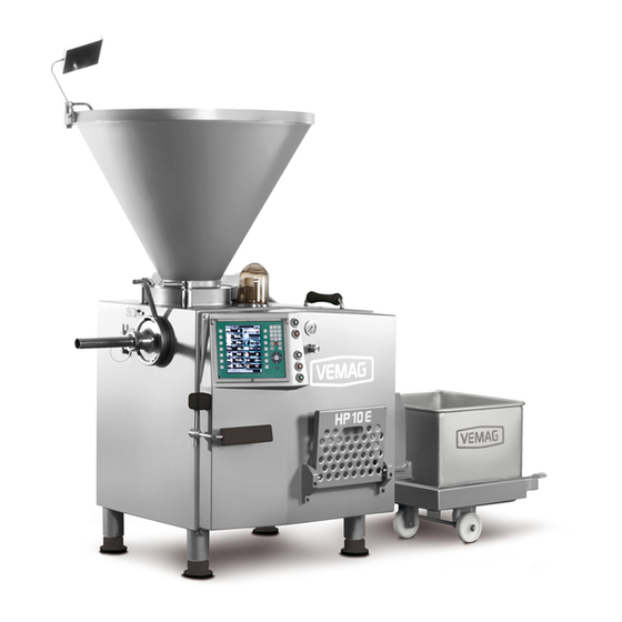
- Page 1 Vacuum filler HP10E - Dairy design (from 168.1004) HP12E - Dairy design (from 168.5003) HP15E - Dairy design (from 168.2010) HP20E - Dairy design (from 168.3009) Operating instructions...
- Page 2 We reserve the right to make technical modifications Issue: 04/13 Version: 2.4 EN (Original operating instructions) Software Version: 00.03.505 © VEMAG Maschinenbau GmbH • Postfach 1620 • D-27266 Verden Phone: +49 42 31 77 70 • Fax: +49 42 31 77 72 41 E-Mail: e-mail@vemag.de http://www.vemag.de...
- Page 3 HP10E / HP12E / HP15E / HP20E - Dairy design Index Index Declaration of conformity 0. Foreword 1. Safety instructions 1.1 Sphere of application 1.2 Use in accordance with purpose 1.3 Explanation of symbols 1.4 General safety instructions 1.5 Special safety instructions 2.
- Page 4 Index HP10E / HP12E / HP15E / HP20E - Dairy design 6.6.2 Start/stop methods 6-24 6.6.2.1 Knee I 6-24 6.6.2.2 Knee II 6-24 6.6.2.3 Remote end 6-24 6.6.2.4 Remote stop 6-24 6.6.2.5 Remote II 6-24 6.6.3 Basic parameters 6-25 6.6.3.1 Weight 6-25 6.6.3.2 First portion...
- Page 5 HP10E / HP12E / HP15E / HP20E - Dairy design Index Working with the minced meat line and forming machine 6-48 6.6.4.43 Weight groups 6-48 6.6.4.44 Group position 6-48 6.6.4.45 Group portions 6-49 6.6.4.46 Group pause 6-49 6.6.4.47 Belt control (analog output 1) 6-50 6.6.4.48 Belt control (analog output 2)
- Page 6 Index HP10E / HP12E / HP15E / HP20E - Dairy design 8.8 Six-monthly maintenance 8-15 8.8.1 Feed unit seals 8-15 8.8.2 Vacuum pump 8-15 8.9 Annual maintenance 8-16 8.9.1 Feed unit drive and feed unit seals 8-16 8.9.2 Vacuum pump 8-16 8.10 Biennial maintenance...
- Page 7 HP10E / HP12E / HP15E / HP20E - Dairy design Declaration of conformity Declaration of conformity reflecting the intention of EC Machinery Directive 2006/42/EC, Annex IIA VEMAG Maschinenbau GmbH Weserstraße 32 27283 Verden (Aller) hereby declare that the Continuous vacuum filler...
- Page 9 The machine is available as: • HP10E / HP12E / HP15E / HP20E in the form of a portioning machine Operating and maintenance instructions for any attachments (optional) can be found in the appropriate separate operating instructions.
- Page 10 0. Foreword HP10E / HP12E / HP15E / HP20E - Dairy design © VEMAG 2013...
- Page 11 1.1 Sphere of application The machine is available as: • HP10E / HP12E / HP15E / HP20E in the form of a portioning machine It can also be fitted with special attachments (optional). 1.2 Use in accordance with purpose The HP10E / HP12E / HP15E / HP20E continuous vacuum filler is desi- gned and built for filling and portioning viscous products.Other products...
- Page 12 1. Safety instructions HP10E / HP12E / HP15E / HP20E - Dairy design 1.3 Explanation of symbols The following symbols appear in these operating instructions, indicating residual hazards when operating the machine or referring the reader to other important information.
- Page 13 HP10E / HP12E / HP15E / HP20E - Dairy design 1. Safety instructions 1.4 General safety instructions • Any person working on or with the machine must have read and un- derstood these operating instructions, in particular the safety instruc- tions.
- Page 14 1. Safety instructions HP10E / HP12E / HP15E / HP20E - Dairy design 1.5 Special safety instructions Danger! To prevent injury, switch off the machine before any work (assembly, dis- mantling, cleaning, maintenance, repair). Then switch off the main switch to disconnect the machine from the mains.
- Page 15 HP10E / HP12E / HP15E / HP20E - Dairy design 2. Description 2. Description 2.1 Overview HP10E / HP12E / HP15E / HP20E Hopper Vacuum pot Vacuum display Vacuum control valve Control panel Adjustable feet Step Knee lever Locking nut...
- Page 16 2. Description HP10E / HP12E / HP15E / HP20E - Dairy design 2.2.2 Feed screw The product is compressed in the hopper by the feed screw (1) and fed to the thread of the double screws with the aid of the vacuum. Spiral stopper (2) improves product feed.
- Page 17 HP10E / HP12E / HP15E / HP20E - Dairy design 2. Description 2.2.4 Filling horn holder The machine is fitted with a filling horn holder (1) at the outlet as standard and this is locked at the outlet by the locking nut (2). Further attachments (optional) can be connected to the filling horn holder.
- Page 18 2. Description HP10E / HP12E / HP15E / HP20E - Dairy design 2.2.5 Controls The controls on the rear of the machine are protected by a cover (1) which is latched with the aid of a toggle (2). Cover Toggle Fig.
- Page 19 HP10E / HP12E / HP15E / HP20E - Dairy design 2. Description The following controls are arranged on the control panel on the front of the machine next to the portioning computer: • ON switch (1) • OFF switch (2) •...
- Page 20 2. Description HP10E / HP12E / HP15E / HP20E - Dairy design 2.2.6 Knee lever The filling process is switched on and off using the knee lever. It can be adjusted to suit the height and location of the operator.
- Page 21 HP10E / HP12E / HP15E / HP20E - Dairy design 3. Installation and commissioning 3. Installation and commissioning 3.1 Transporting the machine The machine may only be transported using suitable lifting trucks or fork- lift trucks with a capacity of at least 1,500 kg. If at all possible, move the fork-lift/lifting truck under the machine from the outlet side.
- Page 22 3. Installation and commissioning HP10E / HP12E / HP15E / HP20E - Dairy design • Drive the lifting truck / fork-lift truck in under the machine so that fork (1) is located precisely centrally between the feet. Warning! Place planks (2) between the fork and the machine to prevent the machi- ne slipping during transportation.
- Page 23 HP10E / HP12E / HP15E / HP20E - Dairy design 3. Installation and commissioning 3.2 Setting up the machine The machine must stand firmly on all four feet at all times and be as level as possible. There may only be a slight inclination (max. 2°) in the direc- tion of the outlet side to encourage water to drain off after cleaning.
- Page 24 3. Installation and commissioning HP10E / HP12E / HP15E / HP20E - Dairy design 3.3 Electrical connection Danger! To prevent injury (electric shock), the electrical connection may be made only by authorised specialist staff or specialist companies. • Inside the machine housing, connect the machine to the main switch (1) of the machine using four-core cable with 3 x phase and 1 x earth wire.
- Page 25 HP10E / HP12E / HP15E / HP20E - Dairy design 3. Installation and commissioning 3.4 Checking direction of rotation Warning! To avoid damage to the machine, the machine may not be operated for more than 10 seconds in the wrong direction of rotation.
- Page 26 3. Installation and commissioning HP10E / HP12E / HP15E / HP20E - Dairy design © VEMAG 2013...
- Page 27 HP10E / HP12E / HP15E / HP20E - Dairy design 4. Setting up 4. Setting up 4.1 General information • To set up the machine, select a double screw housing, the double screws to suit the product to be processed and the required accesso- ries.
- Page 28 4. Setting up HP10E / HP12E / HP15E / HP20E - Dairy design A pin (1) under the coupling pins (2) in the feed cylinder centres the dou- ble screw housing which has the appropriate bore on its end face.
- Page 29 HP10E / HP12E / HP15E / HP20E - Dairy design 4. Setting up 4.3 Fitting the double screws • Inspect the double screws for residual product prior to assembly. • Bring the slots of coupling claws (1) into the correct position in relation to the coupling pins in the feed cylinder by turning the double screws (2) in opposite directions.
- Page 30 4. Setting up HP10E / HP12E / HP15E / HP20E - Dairy design 4.4 Fitting the filling horn holder • Inspect the locking ring and the threads for residual product prior to assembly. • Adjust locking nut (1) so that the handle is between the 10 and 11 o’clock position and insert filling horn holder (2).
- Page 31 HP10E / HP12E / HP15E / HP20E - Dairy design 4. Setting up 4.5 Setting the vacuum 4.5.1 Filling liquid products • Set the vacuum down for filling liquid products. Warning! Before processing any liquid product, check whether the vacuum has been set down.
- Page 32 4. Setting up HP10E / HP12E / HP15E / HP20E - Dairy design 4.6 Fitting the scraper A scraper can be fitted to the hopper for product which sticks to the wall of the hopper. Danger! There is a risk of crushing when fitting and removing the scraper. To prevent injury, proceed extremely carefully when fitting and dismantling the part.
- Page 33 HP10E / HP12E / HP15E / HP20E - Dairy design 4. Setting up 4.7 Adjusting the knee lever The knee lever can be adjusted in terms of height (H), angle (W) and projection (A) to suit the height and location of the operator.
- Page 34 4. Setting up HP10E / HP12E / HP15E / HP20E - Dairy design © VEMAG 2013...
- Page 35 HP10E / HP12E / HP15E / HP20E - Dairy design 5. Operation 5. Operation 5.1 Working with the machine To start production with the machine, proceed as follows: • Set up the machine for the product to be filled. Section 4 •...
- Page 36 5. Operation HP10E / HP12E / HP15E / HP20E - Dairy design • Use the portioning computer to select a filling program and check whether the double screws are correctly selected in the portioning computer. Section 6 • Set the vacuum required for the product to be filled at the vacuum control valve.
- Page 37 HP10E / HP12E / HP15E / HP20E - Dairy design 5. Operation 5.2 Working with provisional drive Should the portioning computer of the machine fail, it is possible to conti- nue operating the machine using provisional drive. In this mode, you can run the machine hopper empty at approx.
- Page 38 5. Operation HP10E / HP12E / HP15E / HP20E - Dairy design © VEMAG 2013...
- Page 39 HP10E / HP12E / HP15E / HP20E - Dairy design 6. Graphical control 6. Graphical control This section introduces the individual controls of the graphical control system. • How is the control panel arranged? • How is the screen arranged? •...
- Page 40 6. Graphical control HP10E / HP12E / HP15E / HP20E - Dairy design Function keys Colour screen Keypad © VEMAG 2013...
- Page 41 HP10E / HP12E / HP15E / HP20E - Dairy design 6. Graphical control 6.1 Control panel The colour screen and the keys are integrated in the green control panel. The screen is divided into various fields. Section 6.2 There are seven function keys to both the left and the right of the screen which you use to activate the associated area of the screen.
- Page 42 6. Graphical control HP10E / HP12E / HP15E / HP20E - Dairy design Header Mode group Program Mode View Product name Start/stop method Parameters Parameters Footer © VEMAG 2013...
- Page 43 HP10E / HP12E / HP15E / HP20E - Dairy design 6. Graphical control 6.2 Screen The screen is divided into five different areas: • Header • Program and mode (mode group, mode, view, start/stop method) • Parameters on the left-hand side of the screen •...
- Page 44 6. Graphical control HP10E / HP12E / HP15E / HP20E - Dairy design Numerical keypad Key C (Cancel) Padlock key Screen up/down keys Plus/minus keys Cursor keys Enter key © VEMAG 2013...
- Page 45 HP10E / HP12E / HP15E / HP20E - Dairy design 6. Graphical control 6.3 Keypad 6.3.1 Numerical keypad Numerical values are entered using the numerical keypad. Every value entered must be confirmed with Enter. 6.3.2 Key C (Cancel) Key C (Cancel) performs the following functions: •...
- Page 46 6. Graphical control HP10E / HP12E / HP15E / HP20E - Dairy design 6.4 Status and error messages The footer displays status and error messages. You can use the arrow keys in the footer to scroll through the last 100 messages. To do this, you need to activate the footer using the cursor keys.
- Page 47 HP10E / HP12E / HP15E / HP20E - Dairy design 6. Graphical control 6.5 Principles of operation This section covers the principles of operating the portioning computer. • How are programs selected and edited? • How are programs imported and exported with the aid of a USB stick? •...
- Page 48 6. Graphical control HP10E / HP12E / HP15E / HP20E - Dairy design Program number Product name Program list with action buttons 6-10 © VEMAG 2013...
- Page 49 HP10E / HP12E / HP15E / HP20E - Dairy design 6. Graphical control 6.5.1 Select and edit programs In the Program field you can select, edit, copy and delete filling programs and also enter product names for the individual programs.
- Page 50 6. Graphical control HP10E / HP12E / HP15E / HP20E - Dairy design USB stick plugged in detected Load recipes 6-12 © VEMAG 2013...
- Page 51 HP10E / HP12E / HP15E / HP20E - Dairy design 6. Graphical control 6.5.2 Importing and exporting programs using a USB stick You can import and export filling programs using a USB stick. The USB stick is plugged into the rear of the control board.
- Page 52 6. Graphical control HP10E / HP12E / HP15E / HP20E - Dairy design Mode group Mode View 6-14 © VEMAG 2013...
- Page 53 HP10E / HP12E / HP15E / HP20E - Dairy design 6. Graphical control 6.5.3 Select mode group, mode and view In the Operating mode field you can select mode group and mode and set the view required for each application. The modes which can be selected are determined by the machine type and the machine configuration.
- Page 54 6. Graphical control HP10E / HP12E / HP15E / HP20E - Dairy design Start/stop method Attachment / Optional Attachment 6-16 © VEMAG 2013...
- Page 55 HP10E / HP12E / HP15E / HP20E - Dairy design 6. Graphical control 6.5.4 Select start/stop method In the Start/stop method field you can select the start/stop method and the attachments used. • Press the Start/stop method key. • Select the Start/stop method field using the cursor key.
- Page 56 6. Graphical control HP10E / HP12E / HP15E / HP20E - Dairy design 6-18 © VEMAG 2013...
- Page 57 HP10E / HP12E / HP15E / HP20E - Dairy design 6. Graphical control 6.5.5 Make settings (language, date/time, password) You can select various settings in the View field. • Press the Operating mode function key. • Select the View field using the bottom cursor key.
- Page 58 6. Graphical control HP10E / HP12E / HP15E / HP20E - Dairy design 6-20 © VEMAG 2013...
- Page 59 HP10E / HP12E / HP15E / HP20E - Dairy design 6. Graphical control 6.5.6 Set up userkey Access to certain functions can be blocked with the aid of the userkey. The userkey has five different user types: • Program locking (switch programs, enter weight corrections and per- form a linking horn test) •...
- Page 60 6. Graphical control HP10E / HP12E / HP15E / HP20E - Dairy design 6-22 © VEMAG 2013...
- Page 61 HP10E / HP12E / HP15E / HP20E - Dairy design 6. Graphical control 6.6. Mode groups, modes, start/stop methods and parameters This section introduces the various mode groups, modes, start/stop methods and parameters. • What mode groups are there? •...
- Page 62 6. Graphical control HP10E / HP12E / HP15E / HP20E - Dairy design 6.6.1 Mode groups, modes and views Use the Operating mode function key to select the mode group, mode and view. You can set the mode groups and modes in the Service area.
- Page 63 HP10E / HP12E / HP15E / HP20E - Dairy design 6. Graphical control 6.6.3 Basic parameters The basic parameters are displayed on the left-hand side of the screen. These parameters are required for the majority of applications. The parameters cannot be scrolled.
- Page 64 6. Graphical control HP10E / HP12E / HP15E / HP20E - Dairy design 6.6.3.2 First portion Display: First portion Unit: Gramme [g] Resolution: 0.1 g/1 g Setting range: 0 – 999 g Application: Portioning programs (not for weight groups, “Continuous”...
- Page 65 HP10E / HP12E / HP15E / HP20E - Dairy design 6. Graphical control 6.6.3.4 Pause Display: Pause Unit: Milliseconds [ms] Resolution: 1 ms Setting range: 0 – 9,999 ms / -1 = single portions Application: Portioning programs (not for “LPG” or “Continuous” modes) •...
- Page 66 6. Graphical control HP10E / HP12E / HP15E / HP20E - Dairy design 6.6.3.6 Speed Display: Speed Unit: Per cent [%] Resolution: 0.1 % Setting range: 0 – 100 % Application: All applications (not for pressure control) • Enter speed.
- Page 67 HP10E / HP12E / HP15E / HP20E - Dairy design 6. Graphical control 6.6.3.7 Individual speed Display: Individual speed Unit: Per cent [%] Resolution: 0,1 % Setting range: 25.0 – 75.0 % Application: Double outlet • Enter speed. • Press Enter.
- Page 68 6. Graphical control HP10E / HP12E / HP15E / HP20E - Dairy design 6.6.3.10 Portions per minute Display: Portions per minute Unit: Number Resolution: Setting range: 1.0 – speed limit Application: Cutter / continuous cutter / continuous PPM • Enter the portions per minute.
- Page 69 HP10E / HP12E / HP15E / HP20E - Dairy design 6. Graphical control 6.6.4 Supplementary parameters The supplementary parameters are displayed on the right-hand side of the screen. These parameters can be summarized in parameter sets for your applications. It is possible to scroll through the parameters.
- Page 70 6. Graphical control HP10E / HP12E / HP15E / HP20E - Dairy design 6.6.4.4 Link offset/clip offset/knife offset (minced meat line) Display: Twist delay / Clip offset / Knife offset Unit: Milliseconds [ms] Resolution: 1 ms Setting range: -3,000 – +3,000 ms (default for linking = -25,...
- Page 71 HP10E / HP12E / HP15E / HP20E - Dairy design 6. Graphical control 6.6.4.6 Select pumping system Display: Pumping system Selection: Rotary vane pump type (e.g. 10-rotor) Application: Fillers with rotary vane pump • Enter rotary vane pump type. •...
- Page 72 6. Graphical control HP10E / HP12E / HP15E / HP20E - Dairy design 6.6.4.9 Metal detection Display: Metal detection Selection: Off / Manual / Reject system Unit: Gramme [g] / Milliseconds [ms] / Speed [%] Resolution: 1 g / 1 ms / 1 % Setting range: 1 –...
- Page 73 HP10E / HP12E / HP15E / HP20E - Dairy design 6. Graphical control 6.6.4.11 Synchronizing the machine using an external signal Display: Portions per signals Selection: Off / Number Unit: Number Resolution: Setting range: 1 – 999,999 Application: Continuous mode and portioning controlled by machine downstream (optional) •...
- Page 74 6. Graphical control HP10E / HP12E / HP15E / HP20E - Dairy design Working with sausage lines 6.6.4.13 Product type Display: Product type Selection: Cooked sausage / Fresh sausage Application: LPG 208, LPG 209 • Enter product type • Press Enter.
- Page 75 HP10E / HP12E / HP15E / HP20E - Dairy design 6. Graphical control 6.6.4.16 Remaining portions Display: Remaining portions Unit: Portion Resolution: Setting range: 0 – 50 / -1 = Off Application: LPG 208, LPG 209, FSL 210, FSL 211 •...
- Page 76 6. Graphical control HP10E / HP12E / HP15E / HP20E - Dairy design 6.6.4.18 Calibre and sausage length Display: Calibre / Sausage length Unit: Millimeter [mm] Resolution: 1 mm Setting range: 14 – 40 mm (FSL 210) / 14 – 50 mm (FSL 211)
- Page 77 HP10E / HP12E / HP15E / HP20E - Dairy design 6. Graphical control 6.6.4.21 Conveyor belt calibre/discharge conveyor calibre Display: Conveyor belt calibre/discharge conveyor calibre Unit: Millimeter [mm] Resolution: 1 mm Setting range: dependent on calibre Application: FSL 210 / FSL 211 (conveyor belt calibre only) •...
- Page 78 6. Graphical control HP10E / HP12E / HP15E / HP20E - Dairy design Working with the hanging machine 6.6.4.24 Calibre and sausage length Display: Calibre / Sausage length Unit: Millimetre [mm] Resolution: 1 mm Setting range: 8 – 52 mm (depends on mode) / 1 – 32,000 mm...
- Page 79 HP10E / HP12E / HP15E / HP20E - Dairy design 6. Graphical control 6.6.4.27 Sausages on last hook Display: Sausages on last hook Unit: Number Resolution: Setting range: 1 – 50 Application: AH 204, AH 212 • Enter the number of sausages to hang on the last hook.
- Page 80 6. Graphical control HP10E / HP12E / HP15E / HP20E - Dairy design 6.6.4.29 Hooks per stick Display: Hooks per stick Unit: Number Resolution: Setting range: 1 - 55 (0 = Off) Application: AH 204, AH 212 • Enter the number of hooks which should be gathered on one smoke stick.
- Page 81 HP10E / HP12E / HP15E / HP20E - Dairy design 6. Graphical control 6.6.4.32 End of stick Display: End of stick Selection: Stop / filled portions / empty casing Unit: Number / Millimeter [mm] Resolution: 1 / 1 mm Setting range: 0 –...
- Page 82 6. Graphical control HP10E / HP12E / HP15E / HP20E - Dairy design 6.6.4.34 End of portioning (LPV 802 and DHV 841 only) Display: End of portioning Selection: Immediate / Even number Application: AH 204 (LPV 802 and DHV 841 only) •...
- Page 83 HP10E / HP12E / HP15E / HP20E - Dairy design 6. Graphical control 6.6.4.37 Last hook later Display: Last hook later Unit: Millisekunden [ms] Resolution: 1 ms Setting range: 0 – 999 ms Application: AH 204, AH 212 • Enter a delay for the last hook of any stick •...
- Page 84 6. Graphical control HP10E / HP12E / HP15E / HP20E - Dairy design Working with the automatic separation valve 6.6.4.38 Separation valve Display: Separation valve Selection: Off/In portion/Portion end/Line end/Line start/Group end Unit: Milliseconds [ms] Resolution: 1 ms Setting range: 0 –...
- Page 85 HP10E / HP12E / HP15E / HP20E - Dairy design 6. Graphical control 6.6.4.41 Separation valve open Display: Separation valve open Unit: Gramme [g] Resolution: Setting range: 0 – 5,000 g Application: “Continuous” mode • Enter the weight of the filling quantity for which the separation valve is to be open during straight filling.
- Page 86 6. Graphical control HP10E / HP12E / HP15E / HP20E - Dairy design Working with the minced meat line and forming machine 6.6.4.43 Weight groups Display: Weight groups Unit: Number Resolution: Setting range: 0 (=off) – 99 Application: Forming machine FM 250 (kebab production) •...
- Page 87 HP10E / HP12E / HP15E / HP20E - Dairy design 6. Graphical control 6.6.4.45 Group portions Display: Group portion Unit: Number of portions/gramme g Resolution: 1/0.1 g Setting range: 0 - 99/0.1 g - 60,000.0 g Application: Forming machine FM 250 (kebab production) •...
- Page 88 6. Graphical control HP10E / HP12E / HP15E / HP20E - Dairy design 6.6.4.47 Belt control (analog output 1) Display: Analog output 1 (general applications) / upper belt (forming machine 250) / feed belt (minced meat portioner MMP 220) Unit:...
- Page 89 HP10E / HP12E / HP15E / HP20E - Dairy design 6. Graphical control Working with the scale 6.6.4.49 Number of samples (VEMAG Scale 877) Display: Number of samples Unit: Number Resolution: Setting range: 1 – 99 Application: VEMAG scale 877 •...
- Page 90 6. Graphical control HP10E / HP12E / HP15E / HP20E - Dairy design Working with special devices 6.6.4.52 Casing pusher Display: Casing pusher Selection: Off / On Application: Automatic casing pusher (LPG 208, LPG 209) • Switch casing pusher on or off.
- Page 91 HP10E / HP12E / HP15E / HP20E - Dairy design 6. Graphical control 6.6.4.54 Type of special control Display: Special control Selection Off / Fill / Separate / Start instruction / Ready Application: Special controls using remote-P contact • Select special control.
- Page 92 6. Graphical control HP10E / HP12E / HP15E / HP20E - Dairy design 6.6.4.56 Knife (cutter) Display: Knife Selection: Portion end closed / Portion end open Application: Servo cutter 808 • Select whether the knife leaves the outlet open or closes it at the end of the portion.
- Page 93 HP10E / HP12E / HP15E / HP20E - Dairy design 6. Graphical control 6.6.4.58 Maximum temperature (temperature monitoring for the grinding system) Display: Temperature Unit: Degrees [°C] / Kilogram [kg] Resolution: 0.1 °C / 1 kg Setting range: Off / -19.9 °C – +31.0 °C / 1,0 kg - 99 kg...
- Page 94 6. Graphical control HP10E / HP12E / HP15E / HP20E - Dairy design 6.6.4.60 Hopper vacuum Display: Hopper vacuum Unit: Per cent [%] Resolution: Setting range: 5 – 98 % (control range +/- 1 to 10 %) Application: Vacuum hopper 149 •...
- Page 95 HP10E / HP12E / HP15E / HP20E - Dairy design 6. Graphical control 6.6.4.62 Hopper level (optional) Display: Hopper level Unit: Off / Automatic / Signal+Stop / Signal / Stop / Speed control Application: Monitoring level of hopper (optional) •...
- Page 96 6. Graphical control HP10E / HP12E / HP15E / HP20E - Dairy design 6.6.4.63 Speed limit Display: Speed limit Unit: Per cent [%] / portions per minute [p/min] Resolution: 0.1 % / 1 % / 1 Setting range:: 0 – 100 % / 1 - 999...
- Page 97 HP10E / HP12E / HP15E / HP20E - Dairy design 6. Graphical control © VEMAG 2013 6-59...
- Page 98 6. Graphical control HP10E / HP12E / HP15E / HP20E - Dairy design Operating mode group Operating mode Machine type / Can be combined option with Filling continuous Pressure control Double outlet Twist Twisting horn AH 204 / AH 212...
- Page 99 HP10E / HP12E / HP15E / HP20E - Dairy design 6. Graphical control 6.7 Configurations (operating mode settings) Different configurations can be selected, depending on operating mode group and operating mode. A grinder can be selected in all operating modes except for „Pressure control“.
- Page 100 6. Graphical control HP10E / HP12E / HP15E / HP20E - Dairy design 6-62 © VEMAG 2013...
- Page 101 HP10E / HP12E / HP15E / HP20E - Dairy design 6. Graphical control 6.8 Service This section describes the Service page to which there is general access. • What information is displayed? 6.8.1 Service pages On the Service pages you will find general information about the version of the terminal, the drive controllers and the filler.
- Page 102 6. Graphical control HP10E / HP12E / HP15E / HP20E - Dairy design 6.9 Messages 6.9.1 List of messages If a message should appear which is not included in the list below, please note the fault number and contact VEMAG Customer Service.
- Page 103 HP10E / HP12E / HP15E / HP20E - Dairy design 6. Graphical control Number Message Cause Remedy IO module A6 IO module A6 is not present or not Check that module A6 is firmly functioning properly. seated; replace the module if necessary.
- Page 104 6. Graphical control HP10E / HP12E / HP15E / HP20E - Dairy design Number Message Cause Remedy ********** too light Scale 877 The sample is min. 20 g To have the sample weight accepted, lighter than the set weight. place the sample on the scale again.
- Page 105 HP10E / HP12E / HP15E / HP20E - Dairy design 6. Graphical control Number Message Cause Remedy Machine parameters are Serious problem when loading Software update or reinstallation. missing machine parameters. Make a note of the error number and inform the VEMAG Customer Service team.
- Page 106 6. Graphical control HP10E / HP12E / HP15E / HP20E - Dairy design Number Message Cause Remedy Target position timeout The main drive has reached the Update is needed for the main target position but the „in position“ drive parameter set. Inform VE- signal has not been sent.
- Page 107 HP10E / HP12E / HP15E / HP20E - Dairy design 6. Graphical control Number Message Cause Remedy Jumper A-G is misplaced The jumper A-G is not permitted in Change the operating mode or in the remote control this operating mode.
- Page 108 6. Graphical control HP10E / HP12E / HP15E / HP20E - Dairy design Number Message Cause Remedy Weight/speed limits knife The value range for input depends offset on another parameter and vice versa. input limit reached The value range for input depends on another parameter and vice versa.
- Page 109 HP10E / HP12E / HP15E / HP20E - Dairy design 6. Graphical control Number Message Cause Remedy Perform maintenance! Indication that servicing is required Perform servicing in accordance on the machine. with the operating instructions. Maintenance acknowl- Maintenance reminder confirmed edged by user by user.
- Page 110 6. Graphical control HP10E / HP12E / HP15E / HP20E - Dairy design Number Message Cause Remedy Twist drive application Fault in the application module. Note the numbers of all current This fault occurs in combination faults and contact VEMAG Service.
- Page 111 HP10E / HP12E / HP15E / HP20E - Dairy design 6. Graphical control Number Message Cause Remedy External drive 1 timeout The reference movement of the Check the reference sensor and first drive of attachment 2 took too the application module. If there is long.
- Page 112 6. Graphical control HP10E / HP12E / HP15E / HP20E - Dairy design Number Message Cause Remedy 20006 Safety cover open (casing Casing pusher safety cover is pusher) open 20007 Safety cover open Casing magazine safety cover is open 20008...
- Page 113 HP10E / HP12E / HP15E / HP20E - Dairy design 6. Graphical control Number Message Cause Remedy 20202 Link point length (filling pause too short 20203 1st link point length (filling pause too short) 20204 Link point stretch (filling speed too high)
- Page 114 6. Graphical control HP10E / HP12E / HP15E / HP20E - Dairy design Number Message Cause Remedy 20225 Gripper swivel drive refe- Drive could not be referenced in rencing failed the specified time 20226 Casing applier drive refe- Drive could not be referenced in...
- Page 115 HP10E / HP12E / HP15E / HP20E - Dairy design 6. Graphical control Number Message Cause Remedy 50203 No hook detected 50204 Additional hooks not pos- Additional hooks > 0, but no full Set additional hooks to 0 or sible — group loading load detected.
- Page 116 6. Graphical control HP10E / HP12E / HP15E / HP20E - Dairy design Number Message Cause Remedy 50921 External drive 3 applica- There is a communication error Make a note of the numbers of all tion error between the application module errors displayed before this error of attachment 2 and A1 (PC).
- Page 117 HP10E / HP12E / HP15E / HP20E - Dairy design 7. Cleaning 7. Cleaning 7.1 General information The machine and any attachments and additional devices (optional) must be cleaned daily. Danger! To prevent injury, take the following measures before cleaning.
- Page 118 7. Cleaning HP10E / HP12E / HP15E / HP20E - Dairy design 7.2.2 Double screws • Once the filling horn holder is removed, the double screws can be removed by pulling them out horizontally, holding the screws steady with the other hand.
- Page 119 HP10E / HP12E / HP15E / HP20E - Dairy design 7. Cleaning • Twist the spindle in far enough for the extraction device to catch and pull the double screw housing a little way out of the feed cylinder. Fig. 7-4 Extraction device catching •...
- Page 120 7. Cleaning HP10E / HP12E / HP15E / HP20E - Dairy design • Pull the double screw housing right out of the feed cylinder by hand, holding the housing steady with the other hand. Fig. 7-6 Removing the double screw housing •...
- Page 121 HP10E / HP12E / HP15E / HP20E - Dairy design 7. Cleaning 7.2.4 Hopper Danger! There is a risk of crushing when fitting/removing the feed screw. To pre- vent injury, proceed extremely carefully when fitting and dismantling the part. •...
- Page 122 7. Cleaning HP10E / HP12E / HP15E / HP20E - Dairy design • Remove the sealing ring (1) from the hopper flange (2). Use the ap- propriate tool at the cleaning plug (3) to do this. Sealing ring Hopper flange Cleaning plug Fig.
- Page 123 HP10E / HP12E / HP15E / HP20E - Dairy design 7. Cleaning • Open the cover (1) of the hopper. Hold the cover firmly by the handles (2) as you do so. Cover Handle Fig. 7-10 Cover Warning! Proceed carefully when opening the cover to avoid any damages of the hopper.
- Page 124 7. Cleaning HP10E / HP12E / HP15E / HP20E - Dairy design 7.2.5 Scraper • Pull scraper (1) off retaining bolt (2) of the feed screw. Scraper Retaining bolt Fig. 7-11 Dismantling the scraper © VEMAG 2013...
- Page 125 HP10E / HP12E / HP15E / HP20E - Dairy design 7. Cleaning 7.2.6 Vacuum system • Remove the vacuum pot. • Take hold of the float valve on the valve body (1) and pull it off the intake pipe of the vacuum line in a horizontal direction.
- Page 126 7. Cleaning HP10E / HP12E / HP15E / HP20E - Dairy design Warning! Before cleaning, you must plug the cleaning plug onto the intake pipe of the vacuum line to protect the vacuum pump. Cleaning plug (1) is located behind the cover on the rear of the machine.
- Page 127 HP10E / HP12E / HP15E / HP20E - Dairy design 7. Cleaning 7.3 Cleaning the machine All product contact and incidental contact areas are ready to be cleaned and then inspected. Clean the machine housing, the hopper, the cover, the feed screw and all the parts which have been removed thoroughly with hot water and a brush or use low-pressure mechanical cleaning equipment (max.
- Page 128 7. Cleaning HP10E / HP12E / HP15E / HP20E - Dairy design 7.4 Cleaning schedule 7.4.1 General recommendations All information relates to single-shift operation. • Predominant use should be made of alkaline foam cleaning agents. • To remove mineral deposits such as limescale, use acid foam cleaning agents as required (usually 1x a week).
- Page 129 HP10E / HP12E / HP15E / HP20E - Dairy design 7. Cleaning Recommended cleaning agents: Europe Application Characteristics Clean Disinfect Foam Manual Rinse P3-steril Combined cleaning agent and disinfectant, slightly alkaline P3-topax 19 Quorum Foam cleaning agent, alkaline P3-topactive 200...
- Page 130 7. Cleaning HP10E / HP12E / HP15E / HP20E - Dairy design 7.4.3 Chlorine-containing alkaline cleaning agents Perform cleaning as follows: • Initial rinse with water to remove coarse dirt • Application of foam to the surfaces for cleaning using a 2 – 5 % soluti- on of P3-topax 66 (alkaline) or 2 –...
- Page 131 HP10E / HP12E / HP15E / HP20E - Dairy design 7. Cleaning 7.4.4 Specialist cleaning agent for machine interior Check inside the machine regularly for the build-up of germs and dirt. Clean the inside of the machine if the dirt is excessive.
- Page 132 7. Cleaning HP10E / HP12E / HP15E / HP20E - Dairy design 7.5 Lubrication and assembly • Thoroughly lubricate all dismantled, cleaned and dried parts (apart from vacuum system parts) with a corrosion-inhibiting oil which is safe for food use.
- Page 133 HP10E / HP12E / HP15E / HP20E - Dairy design 8. Maintenance 8. Maintenance 8.1 General information Apart from daily cleaning, the filler needs very little maintenance. The information below describes the maintenance work to be perfor- med by the owner of the machine. The types and quantities of lubricants required are listed in the appendix.
- Page 134 8. Maintenance HP10E / HP12E / HP15E / HP20E - Dairy design • Undo bottom assembly bolt (1) of the front door using spanner (2). Assembly bolt Spanner Fig. 8-2 Opening the front door • Swing open the front door.
- Page 135 HP10E / HP12E / HP15E / HP20E - Dairy design 8. Maintenance • Undo the assembly bolts (1) of the service hatch using screwdriver (2) to assist. Assembly bolt Screwdriver Fig. 8-4 Opening the service hatch • Swing open the service hatch.
- Page 136 8. Maintenance HP10E / HP12E / HP15E / HP20E - Dairy design • Carry out the necessary maintenance work according to the mainte- nance schedule. Section 8.4 • Clean the contact surfaces of the cover seals and lubricate lightly before re-fitting.
- Page 137 HP10E / HP12E / HP15E / HP20E - Dairy design 8. Maintenance 8.2 Grease gun The cartridges for the grease gun supplied are replaced as follows: • Pull piston rod (1) back firmly to the stop. • Unscrew the head of the grease gun (2) and pull out the empty cart- ridge.
- Page 138 8. Maintenance HP10E / HP12E / HP15E / HP20E - Dairy design 8.3 First-time maintenance work Perform the following maintenance work for the first time after the inter- vals given. After that, these measures should be effected in accordance with the maintenance schedule.
- Page 139 HP10E / HP12E / HP15E / HP20E - Dairy design 8. Maintenance 8.4 Maintenance schedule All information relates to single-shift operation. The portioning compu- ter shows the number of operating hours reached in each case. All the maintenance tasks included under one operating hours heading should be performed.
- Page 140 8. Maintenance HP10E / HP12E / HP15E / HP20E - Dairy design 8.5 Daily maintenance 8.5.1 Feed unit seals (lubrication) The feed unit seals must be lubricated daily every time they are cleaned. Use only high-performance grease which is safe for food use.
- Page 141 HP10E / HP12E / HP15E / HP20E - Dairy design 8. Maintenance • Guide the feed screw (1) into the hopper in such a way that the three sliding sleeves (2) are located behind the shoulder (3) of the hopper flange.
- Page 142 8. Maintenance HP10E / HP12E / HP15E / HP20E - Dairy design 8.5.2 Sliding ring (wear) The feed unit seals must be lubricated daily every time they are cleaned. Use only high-performance grease which is safe for food use. •...
- Page 143 Then remove the grease which has escaped. Lubricating nipple Relief bore Fig. 8-11 Lubricating the feed unit drive • If no grease at all escapes at the relief bore, inform VEMAG Customer Service and have the drive/bearing checked. © VEMAG 2013 8-11...
- Page 144 8. Maintenance HP10E / HP12E / HP15E / HP20E - Dairy design 8.6.2 Intake (air filter) There is an air filter in the service hatch on the rear which needs to be cleaned weekly. • Unlatch the toggle on the rear of the machine and open the cover completely.
- Page 145 HP10E / HP12E / HP15E / HP20E - Dairy design 8. Maintenance 8.6.3 Vacuum pump (air filter) An air filter is located in the intake line to the vacuum pump and this needs to be cleaned weekly. • Open the two locking clips (1) of the air filter and remove the filter cover (2).
- Page 146 8. Maintenance HP10E / HP12E / HP15E / HP20E - Dairy design 8.7 Monthly maintenance 8.7.1 Double screw drive (oil level and seals) The oil expansion reservoir of the double screw drive and its cover are attached in a bracket and connected to the double screw drive by a hose.
- Page 147 HP10E / HP12E / HP15E / HP20E - Dairy design 8. Maintenance 8.8 Six-monthly maintenance 8.8.1 Feed unit seals • Have the feed unit seals checked by VEMAG Customer Service. 8.8.2 Vacuum pump Operating instructions for vacuum pump © VEMAG 2013...
- Page 148 8. Maintenance HP10E / HP12E / HP15E / HP20E - Dairy design 8.9 Annual maintenance 8.9.1 Feed unit drive and feed unit seals • Have the feed unit checked by VEMAG Customer Service and the feed unit seals replaced. 8.9.2 Vacuum pump...
- Page 149 HP10E / HP12E / HP15E / HP20E - Dairy design 8. Maintenance • Undo the two hose clamps (1) and pull off the two hoses (2). Hose clamp Hose Fig. 8-17 Removing the vacuum pump • Undo the two assembly bolts (1) used to fix the vacuum pump to the base plate.
- Page 150 8. Maintenance HP10E / HP12E / HP15E / HP20E - Dairy design 8.10 Biennial maintenance 8.10.1 Double screw drive (oil change) The oil in the double screw drive should be changed every two years. • Open the service hatch on the right-hand side.
- Page 151 HP10E / HP12E / HP15E / HP20E - Dairy design 8. Maintenance 8.11 Three-yearly maintenance 8.11.1 Feed drive (oil change) The oil in the transmission of the feed drive needs to be changed every three years. • Unlatch the toggle on the rear of the machine and open the cover completely.
- Page 152 8. Maintenance HP10E / HP12E / HP15E / HP20E - Dairy design The oil must come up to the top check bore in the transmission housing of the transmission. • Remove sealing screw (1) from the top check bore. •...
- Page 153 HP10E / HP12E / HP15E / HP20E - Dairy design 9. Troubleshooting 9. Troubleshooting 9.1 General information Any attachments or additional devices (optional) which may be present should be disconnected from the filling machine for troubleshooting purposes. The relevant safety instructions must be followed. Possible faults, causes and the measures you need to take to remedy them are listed below.
- Page 154 9. Troubleshooting HP10E / HP12E / HP15E / HP20E - Dairy design Fault Cause Remedy Weight fluctuations. Unsuitable double screw. Check double screw, use 48 mm double screw pitch for portioning small portions. Double screw and double screw Measure double screw and double housing worn.
- Page 155 Please give the machine number in the event of any query to VEMAG Customer Service or its agents. You will find this on the rating plate on the rear of the filler. It is also embossed on the machine frame.
- Page 156 10. Appendix HP10E / HP12E / HP15E / HP20E - Dairy design 10.2 Technical data HP10E / HP12E / HP15E / HP20E HP10E HP12E HP15E HP20E Filling rate: bis 5,700 kg/h (double bis 3,600 kg/h (double bis 9,800 kg/h (double...
- Page 157 HP10E / HP12E / HP15E / HP20E - Dairy design 10. Appendix 10.3 Dimensional drawings HP10E / HP12E / HP15E / HP20E © VEMAG 2013 10-3...
- Page 158 10. Appendix HP10E / HP12E / HP15E / HP20E - Dairy design 10.4 Lubricants 10.4.1 Double screw drive Type of oil: transmission oil Oil capacity: approx. 3.0 l Viscosity class: ISO VG 100 to DIN 51519 Quality: C-LP to DIN 51502 Example: Fuchs Gearmaster SYN 100 (order no.
- Page 159 HP10E / HP12E / HP15E / HP20E - Dairy design 10. Appendix 10.5 Accessories 10.5.1 Miscellaneous accessories Component Order no. Filling horn holder 148315000 Filling horn nut for attaching filling horn 930100017 Blind plug double screw housing 920001010 Cleaning plug...
- Page 160 10. Appendix HP10E / HP12E / HP15E / HP20E - Dairy design 10.6 Disposal 10.6.1 General information The machine must be dismantled at the end of its service life and dispo- sed of properly in accordance with the applicable national environmental regulations.
- Page 161 ● Clean the fan cowlings, fan wheels, the ventilation grilles and cool- ● Check the level and the colour of the oil (i) ing fins No low level indication from the level switch (a), ... KC 0016 D VEMAG page 1 0870146800 / 100111...
- Page 162 Food applications (NSF H1); Remark VEMAG-part no. 1l-packaging: Nominal suction capacity m³/h 16 / 19 052.001.029 (50Hz/60Hz) Filling quantity, approx. [l] hPa (=mbar) Ultimate pressure abs. Motor nominal rating 0.55 (50Hz/60Hz) KC 0016 D VEMAG page 2 0870146800 / 100111...
- Page 163 -mark. Busch Produktions GmbH Schauinslandstr. 1 79689 Maulburg Germany declare that vacuum pumps KC 0016 D VEMAG in accordance with the European Directives: – “Machinery” 2006/42/EC, – “Electrical Equipment Designed for Use within Certain Voltage Limits” (so called “Low Voltage”) 2006/95/EC, –...
- Page 164 In order to exclude this possible cause: either temporarily disconnect the oil return line from its connection near the exhaust opening and close it squirt oil through the gas discharge (g) KC 0016 D VEMAG page 4 0870146800 / 100111...
- Page 165 Drain condensate regularly Condensate could not be compressed and thus broke a vane KC 0016 D VEMAG page 5 0870146800 / 100111...
- Page 166 Temperature of the inlet gas too high Observe the permitted temperatures for the inlet gas The exhaust filter is partially clogged Replace the exhaust filter Not enough oil in the reservoir Top up oil KC 0016 D VEMAG page 6 0870146800 / 100111...
- Page 167 The oil foams Mixing of incompatible oils Flush the vacuum pump Replace the exhaust filter Fill in new oil (Ú page 1: Maintenance) Make sure the proper oil is used for topping up KC 0016 D VEMAG page 7 0870146800 / 100111...
Need help?
Do you have a question about the HP10E and is the answer not in the manual?
Questions and answers