
Subscribe to Our Youtube Channel
Related Manuals for VEMAG ROBOT HP7C


Summary of Contents for VEMAG ROBOT HP7C
- Page 1 Vacuum filler ROBOT HP7C (from 146.0132) ROBOT HP10C (from 142.1543) ROBOT HP15C (from 143.1549) ROBOT HP17C (from 147.1552) Operating instructions...
- Page 2 We reserve the right to make technical modifications Issue: 02/06 Version: 1.2 EN © VEMAG Maschinenbau GmbH • Postfach 1620 • D-27266 Verden Phone: +49 42 31 77 70 • Fax: +49 42 31 77 72 41 e-mail: e-mail@vemag.de http://www.vemag.de...
- Page 3 1.2 Use in accordance with purpose 1.3 Explanation of symbols 1.4 General safety instructions 1.5 Special safety instructions 2. Description 2.1 Overview ROBOT HP7C / HP10C / HP15C / HP17C 2-1 2.2 Brief description 2.2.1 Hopper 2.2.2 Feed screw 2.2.3 Double screws 2.2.4 Filling horn holder...
- Page 4 Index ROBOT HP7C / HP10C / HP15C / HP17C 5. Operation 5.1 Working with the machine 5.2 Working with provisional drive 6. Cleaning 6.1 General information 6.2 Removing parts to be cleaned 6.2.1 Filling horn and filling horn holder 6.2.2 Linking horn (optional) 6.2.3 Linking gear (optional)
- Page 5 8.2 Troubleshooting table 9. Appendix 9.1 General information 9.2 Technical data ROBOT HP7C / HP10C / HP15C / HP17C 9.3 ROBOT HP7C / HP10C / HP15C / HP17C dimensional drawings 9.4 Vacuum system 9.5 Hydraulics plan 9.6 Electrical control panel 9.7 Power electronics...
- Page 6 Index ROBOT HP7C / HP10C / HP15C / HP17C © VEMAG 2004...
- Page 7 These operating instructions cover all the information required to operate the vacuum filler. Two versions of the machine are available: • ROBOT HP7C / HP10C / HP15C / HP17C in the form of a portioning machine • ROBOT HP7C / HP10C / HP15C / HP17C in the form of a portioning...
- Page 8 0. Foreword ROBOT HP7C / HP10C / HP15C / HP17C © VEMAG 2004...
- Page 9 1.1 Sphere of application Two versions of the continuous vacuum filler are available: • ROBOT HP7C / HP10C / HP15C / HP17C in the form of a portioning machine • ROBOT HP7C / HP10C / HP15C / HP17C in the form of a portioning and linking machine It can also be fitted with special attachments (optional).
- Page 10 1. Safety instructions ROBOT HP7C / HP10C / HP15C / HP17C 1.3 Explanation of symbols The following symbols appear in these operating instructions, indicating residual hazards when operating the machine or referring the reader to other important information. Danger! This warning symbol refers to important instructions which must be followed to prevent faulty operation which could pose a threat to human life or lead to injury.
- Page 11 Corrosion at the contacts can lead to switching errors. • It is prohibited to remove, switch off or override safety devices. In the event of damage to safety devices, inform VEMAG Customer Service immediately. • Warning signs on the machine may not be removed or painted over.
- Page 12 1. Safety instructions ROBOT HP7C / HP10C / HP15C / HP17C 1.5 Special safety instructions Danger! To prevent injury, switch off the machine before any work (assembly, dismantling, cleaning, maintenance, repair). Then switch off the main switch to disconnect the machine from the mains.
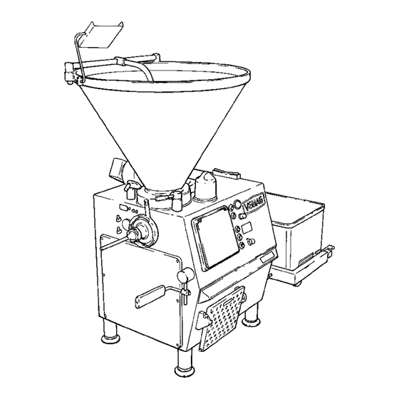
- Page 13 ROBOT HP7C / HP10C / HP15C / HP17C 2. Description 2. Description 2.1 Overview ROBOT HP7C / HP10C / HP15C / HP17C 1 Hopper 2 Vacuum pot 3 Vacuum display 4 Vacuum control valve 5 Trolley 6 Lifting/tipping device (optional)
- Page 14 2. Description ROBOT HP7C / HP10C / HP15C / HP17C 2.2.2 Feed screw The product is compressed in the hopper by the feed screw (1) and fed to the thread of the double screws with the aid of the vacuum. Spiral stopper (2) improves product feed.
- Page 15 ROBOT HP7C / HP10C / HP15C / HP17C 2. Description 2.2.4 Filling horn holder The machine is fitted with a filling horn holder (1) at the outlet as standard and this is locked at the outlet by the locking nut (2). The filling horn (3) is attached to the filling horn holder with the aid of the filling horn nut (4).
- Page 16 2. Description ROBOT HP7C / HP10C / HP15C / HP17C 2.2.6 Controls The main switch (1) which switches the power supply to the machine on and off can be found on the rear of the machine housing. Attachments and additional devices (optional) can be connected to the power supply of the machine via equipment socket (2).
- Page 17 ROBOT HP7C / HP10C / HP15C / HP17C 2. Description The following controls are arranged on the control panel on the front of the machine next to the portioning computer: • ON switch (1) • OFF switch (2) • UP key (3) for lifting/tipping device (optional) •...
- Page 18 2. Description ROBOT HP7C / HP10C / HP15C / HP17C STOP key (optional) This key stops the trolley hoist of the lifting/tipping device (optional). DOWN key (optional) This key lowers the trolley hoist of the lifting/tipping device (optional). The trolley hoist stops automatically as soon as the trolley is 500 mm above the ground.
- Page 19 ROBOT HP7C / HP10C / HP15C / HP17C 2. Description 2.2.7 Knee lever The filling process is switched on and off using the knee lever. It can be adjusted to suit the height and location of the operator. Section 4.9 2.2.8 Step...
- Page 20 2. Description ROBOT HP7C / HP10C / HP15C / HP17C © VEMAG 2004...
- Page 21 ROBOT HP7C / HP10C / HP15C / HP17C 3. Installation and commissioning 3. Installation and commissioning 3.1 Transporting the machine The machine may only be transported using suitable lifting trucks or fork- lift trucks with a capacity of at least 1,500 kg. If at all possible, move the fork-lift/lifting truck under the machine from the outlet side.
- Page 22 3. Installation and commissioning ROBOT HP7C / HP10C / HP15C / HP17C • Drive the lifting truck / fork-lift truck in under the machine so that fork (1) is located precisely centrally between the feet. Warning! Place planks (2) between the fork and the machine to prevent the machine slipping during transportation.
- Page 23 ROBOT HP7C / HP10C / HP15C / HP17C 3. Installation and commissioning 3.2 Setting up the machine The machine must stand firmly on all four feet at all times and be as level as possible. There may only be a slight inclination (max. 2°) in the direction of the outlet side to encourage water to drain off after cleaning.
- Page 24 3. Installation and commissioning ROBOT HP7C / HP10C / HP15C / HP17C 3.3 Electrical connection Danger! To prevent injury (electric shock), the electrical connection may be made only by authorised specialist staff or specialist companies. • Inside the machine housing, connect the machine to the main switch (1) of the machine using four-core cable with 3 x phase and 1 x earth wire.
- Page 25 ROBOT HP7C / HP10C / HP15C / HP17C 3. Installation and commissioning 3.4 Checking direction of rotation Warning! To avoid damage to the machine, the machine may not be operated for more than 10 seconds in the wrong direction of rotation.
- Page 26 3. Installation and commissioning ROBOT HP7C / HP10C / HP15C / HP17C 3.5 Levelling the lifting/tipping device (optional) The trolley hoist of the lifting/tipping device is set at the factory with the feet of the machine screwed in and on a level floor (outlet height 1,000 mm).
- Page 27 ROBOT HP7C / HP10C / HP15C / HP17C 3. Installation and commissioning • Undo the two top mounting bolts (1) on the back of drive hood (2) and tap the bolts to release the drive hood. Push the hood and its seal in the direction of the operator side until the pins (3) release the guide grooves and lift it off.
- Page 28 3. Installation and commissioning ROBOT HP7C / HP10C / HP15C / HP17C • Move the arm of the lifting/tipping device into the bottom end position using the DOWN key. Push a trolley into the trolley hoist to check the correct height of the trolley hoist and repeat setting if necessary.
- Page 29 ROBOT HP7C / HP10C / HP15C / HP17C 3. Installation and commissioning • Check that the trolley hoist is level using a spirit level, and push a trolley right into the trolley hoist. Warning! Check whether the locking lever (1) is properly locked and is holding the trolley securely in the trolley hoist.
- Page 30 3. Installation and commissioning ROBOT HP7C / HP10C / HP15C / HP17C 3-10 © VEMAG 2004...
- Page 31 ROBOT HP7C / HP10C / HP15C / HP17C 4. Setting up 4. Setting up 4.1 General information • To set up the machine, select a double screw housing, the double screws to suit the product to be processed and the required accessories.
- Page 32 4. Setting up ROBOT HP7C / HP10C / HP15C / HP17C A pin (1) under the coupling pins (2) in the feed cylinder centres the double screw housing which has the appropriate bore on its end face. The rear part of the housing of the two-part double screw housing likewise has a centring pin for centring the front part of the housing.
- Page 33 ROBOT HP7C / HP10C / HP15C / HP17C 4. Setting up 4.3 Fitting the double screws • Position the double screws (1) so that the screw marked left (”links”) is on the left-hand side and the front faces are flush.
- Page 34 4. Setting up ROBOT HP7C / HP10C / HP15C / HP17C 4.4 Fitting the filling horn • Adjust locking nut (1) so that the handle is between the 10 and 11 o’clock position and insert filling horn holder (2). •...
- Page 35 ROBOT HP7C / HP10C / HP15C / HP17C 4. Setting up 4.5 Locking the linking gear (optional) Danger! There is a risk of crushing when swivelling the linking gear in and out. To prevent injury, proceed extremely carefully when fitting and dismantling the part.
- Page 36 4. Setting up ROBOT HP7C / HP10C / HP15C / HP17C 4.6 Fitting the linking horn (optional) • Use a linking horn with the largest possible diameter and shortest possible length related to the size of the casing. • Fit lip seal (1) in linking horn (2) so that the lug of the lip seal is pointing forwards.
- Page 37 ROBOT HP7C / HP10C / HP15C / HP17C 4. Setting up • Insert linking horn (1) into linking head (2) and tighten linking nut (3) using universal spanner (4). Hold the linking head steady with the second universal spanner as you do so.
- Page 38 4. Setting up ROBOT HP7C / HP10C / HP15C / HP17C 4.7 Setting the vacuum 4.7.1 Filling raw and cooked sausage • Set the maximum vacuum for filling raw and cooked sausage. 4.7.2 Filling liquid product (e.g. liver sausage) •...
- Page 39 ROBOT HP7C / HP10C / HP15C / HP17C 4. Setting up 4.8 Fitting the scraper A scraper can be fitted to the hopper for product which sticks to the wall of the hopper. The scraper must be used when processing raw sausage.
- Page 40 4. Setting up ROBOT HP7C / HP10C / HP15C / HP17C 4.9 Adjusting the knee lever The knee lever can be adjusted in terms of height (H), angle (W) and projection (A) to suit the height and location of the operator.
- Page 41 ROBOT HP7C / HP10C / HP15C / HP17C 5. Operation 5. Operation 5.1 Working with the machine To start production with the machine, proceed as follows: • Set up the machine for the product to be filled Section 4 •...
- Page 42 5. Operation ROBOT HP7C / HP10C / HP15C / HP17C • Unlock the locking lever (1) with your foot and pull the trolley out of the trolley hoist. Locking lever Fig. 5-1 Trolley © VEMAG 2004...
- Page 43 ROBOT HP7C / HP10C / HP15C / HP17C 5. Operation • If you want to use the machine to link, test the relevant linking horn for concentricity with the aid of the respective program. Portioning computer user guide • Use the portioning computer to select a filling program and check whether the double screws are correctly selected in the portioning computer.
- Page 44 5. Operation ROBOT HP7C / HP10C / HP15C / HP17C 5.2 Working with provisional drive Should the portioning computer of the machine fail, it is possible to continue operating the machine using provisional drive. • Press the OFF key on the machine control panel.
- Page 45 ROBOT HP7C / HP10C / HP15C / HP17C 6. Cleaning 6. Cleaning 6.1 General information The machine and any attachments and additional devices (optional) must be cleaned daily. Danger! To prevent injury, take the following measures before cleaning. • Press the OFF key on the machine control panel.
- Page 46 6. Cleaning ROBOT HP7C / HP10C / HP15C / HP17C 6.2.2 Linking horn (optional) • Undo linking nut (1) with the universal spanner (2) and remove linking horn (3). Hold the linking head steady with the second universal spanner as you do so.
-
Page 47: Double Screws
ROBOT HP7C / HP10C / HP15C / HP17C 6. Cleaning 6.2.4 Double screws • Screw the screw extractor (1) into the threaded bore of the right-hand double screw and pull the double screws out of the double screw housing, holding the screws steady with the other hand. -
Page 48: Fig
6. Cleaning ROBOT HP7C / HP10C / HP15C / HP17C • Twist the spindle in far enough for the extraction device to catch and pull the double screw housing a little way out of the feed cylinder. Fig. 6-6 Extraction device catching •... - Page 49 You must check the seals of the double screw drive for traces of oil before cleaning. If traces of oil are present, the double screw drive must be overhauled or replaced. In this case inform VEMAG Customer Service. © VEMAG 2004...
- Page 50 6. Cleaning ROBOT HP7C / HP10C / HP15C / HP17C 6.2.6 Hopper Danger! There is a risk of crushing when fitting/removing the feed screw. To prevent injury, proceed extremely carefully when fitting and dismantling the part. • Unlock the two locking levers (1) on the hopper housing and carefully tip the hopper backwards.
- Page 51 ROBOT HP7C / HP10C / HP15C / HP17C 6. Cleaning • Remove the sealing ring (1) from the hopper insert (2). Use the appropriate tool at the cleaning plug (3) to do this. Sealing ring Hopper insert Cleaning plug Fig. 6-11 Feed unit seal 6.2.7 Scraper...
- Page 52 6. Cleaning ROBOT HP7C / HP10C / HP15C / HP17C 6.2.8 Vacuum system • Remove the vacuum pot. • Take hold of the float valve on the valve body (1) and pull it off the intake pipe of the vacuum line in a horizontal direction.
- Page 53 ROBOT HP7C / HP10C / HP15C / HP17C 6. Cleaning Warning! Before cleaning, you must plug the cleaning plug onto the intake pipe of the vacuum line to protect the vacuum pump. The cleaning plug (1) is located on the front of the machine.
- Page 54 6. Cleaning ROBOT HP7C / HP10C / HP15C / HP17C 6.3 Cleaning the machine Clean the machine housing, the hopper, the feed screw, the linking gear (optional) and all the parts which have been removed thoroughly with hot water and a brush and then dry them. The machine is suitable for cleaning with low-pressure cleaning equipment (max.
- Page 55 ROBOT HP7C / HP10C / HP15C / HP17C 6. Cleaning 6.4 Cleaning schedule All details refer to single-shift operation. Cleaning task Cleaning agent Process Equipment Notes Rough cleaning, • by hand, plastic spatula, Begin as soon removal of product mechanically...
- Page 56 6. Cleaning ROBOT HP7C / HP10C / HP15C / HP17C 6.5 Lubrication and assembly • Thoroughly lubricate all dismantled, cleaned and dried parts (apart from vacuum system parts) with a corrosion-inhibiting oil which is safe for food use. Section 9 •...
- Page 57 • Put housing cover back on. Regularly check the hydraulic system of the machine, including all pipe and hose lines, for damage or leaks. Inform VEMAG Customer Service if you find damage or leaks. Warning! DIN 20066 states that the service life of hose lines should not exceed six years.
- Page 58 7. Maintenance ROBOT HP7C / HP10C / HP15C / HP17C 7.2 Grease gun The cartridges for the grease gun supplied are replaced as follows: • Pull piston rod (1) back firmly to the stop. • Unscrew the head of the grease gun (2) and pull out the empty cartridge.
- Page 59 ROBOT HP7C / HP10C / HP15C / HP17C 7. Maintenance 7.4 Maintenance schedule All information relates to single-shift operation. The portioning computer shows the number of operating hours reached in each case. All the maintenance tasks included under one operating hours heading should be performed.
- Page 60 7. Maintenance ROBOT HP7C / HP10C / HP15C / HP17C 7.5 Daily maintenance 7.5.1 Feed unit seals (lubrication) The feed unit seals must be lubricated daily every time they are cleaned. Use only high-performance grease which is safe for food use.
- Page 61 ROBOT HP7C / HP10C / HP15C / HP17C 7. Maintenance • Guide the feed screw (1) into the hopper in such a way that the three sliding sleeves (2) are located behind the shoulder (3) of the hopper flange. •...
- Page 62 Then remove the grease which has escaped. Lubricating nipple Relief bore Fig. 7-4 Lubricating the feed unit drive • If no grease at all escapes at the relief bore, inform VEMAG Customer Service and have the drive/bearing checked. © VEMAG 2004...
- Page 63 ROBOT HP7C / HP10C / HP15C / HP17C 7. Maintenance 7.6.2 Vacuum pump (air filter and oil level) An air filter is located in the intake line to the vacuum pump and this needs to be cleaned weekly. • Remove the housing cover next to the main switch on the rear of the machine.
- Page 64 7. Maintenance ROBOT HP7C / HP10C / HP15C / HP17C The vacuum pump has a closed oil circuit. The oil reservoir is integral to the pump housing. There is a sight glass on each side of the pump for checking the oil level. The oil should reach at least the centre of the sight glass.
- Page 65 ROBOT HP7C / HP10C / HP15C / HP17C 7. Maintenance 7.7 Monthly maintenance 7.7.1 Hydraulic drive (oil level) The tank is underneath the hydraulic drive. There is a sight glass for checking oil level on the front of the tank. The oil should come at least to the centre of the sight glass.
- Page 66 • Attach the electrical case and re-fit the housing cover. Warning! Inform VEMAG Customer Service immediately if there is oil in the relief hose. The seals of the double screw drive must be replaced before production is resumed. 7-10...
- Page 67 ROBOT HP7C / HP10C / HP15C / HP17C 7. Maintenance 7.8 Quarterly maintenance 7.8.1 Vacuum pump (oil change, screens, gas ballast valve) Danger! To prevent injury (burns) do not carry out the following work with the pump still warm from operation, but wait until the pump has cooled down.
- Page 68 7. Maintenance ROBOT HP7C / HP10C / HP15C / HP17C • Undo the two hose clamps (1) and pull off the two hoses (2). Hose clamp Hose Fig. 7-10 Removing the vacuum pump • Undo the two assembly bolts (1) used to fix the vacuum pump to the base plate.
- Page 69 ROBOT HP7C / HP10C / HP15C / HP17C 7. Maintenance There is a drain screw on the side of the pump housing for draining off used oil. • Put the vacuum pump down so that a suitable container can be placed under drain screw (1).
- Page 70 7. Maintenance ROBOT HP7C / HP10C / HP15C / HP17C • Remove angled flange (1) and seal (2). • Take the valve guide, compression spring and valve disc out of the angled flange. • Clean screen (3) by blowing it out. If it is severely contaminated, replace •...
- Page 71 ROBOT HP7C / HP10C / HP15C / HP17C 7. Maintenance There are two screens in the blow-out cover of the deoiler side which have to be checked for contamination and cleaned. • Undo the two assembly bolts (1) and remove blow-out cover (2) and seal (3).
- Page 72 7. Maintenance ROBOT HP7C / HP10C / HP15C / HP17C There are two intake screens in the deoiler housing of the vacuum pump (intake and back-suction). The intake screens need to be checked for contamination and cleaned. • Undo banjo bolt (1) on each side of the deoiler housing and take it out of the opening together with sealing ring (2) and intake screen (3).
- Page 73 ROBOT HP7C / HP10C / HP15C / HP17C 7. Maintenance If the pump housing is very dirty, the gas ballast valve of the vacuum pump will need to be cleaned. • Undo screw (1) and take off cap (2). •...
- Page 74 7. Maintenance ROBOT HP7C / HP10C / HP15C / HP17C 7.9 Six-monthly maintenance 7.9.1 Feed unit seals • Have the feed unit seals checked by VEMAG Customer Service. 7-18 © VEMAG 2004...
- Page 75 ROBOT HP7C / HP10C / HP15C / HP17C 7. Maintenance 7.10 Annual maintenance 7.10.1 Hydraulic drive (oil change and filter cartridge) To change the hydraulic oil, the oil reservoir for the hydraulic drive is fitted with a drain hose, the free end of which is secured to a blind connector by a jubilee clip.
- Page 76 Then screw the screw cap back onto the filter • Re-fit the housing cover. 7.10.2 Feed unit drive and feed unit seals • Have the feed unit checked by VEMAG Customer Service and the feed unit seals replaced. 7-20 © VEMAG 2004...
- Page 77 ROBOT HP7C / HP10C / HP15C / HP17C 7. Maintenance 7.10.3 Vacuum pump (air de-oiling element) The vacuum pump air de-oiling element can become contaminated by particles of dirt in the air drawn in after a prolonged operating period. As it cannot be cleaned, the air de-oiling element has to be replaced.
- Page 78 • Attach the electrical case and re-fit the housing cover. Warning! Inform VEMAG Customer Service immediately if there is oil in the relief hose. The seals of the double screw drive must be replaced before production is resumed. 7-22...
- Page 79 ROBOT HP7C / HP10C / HP15C / HP17C 8. Troubleshooting 8. Troubleshooting 8.1 General information Any attachments or additional devices (optional) which may be present should be disconnected from the filling machine for troubleshooting purposes. The relevant safety instructions must be followed. Possible faults, causes and the measures you need to take to remedy them are listed below.
- Page 80 8. Troubleshooting ROBOT HP7C / HP10C / HP15C / HP17C Fault Cause Remedy Machine feeds continuously • Portioning computer or power • Have parts replaced by in portioning mode. electronics defective. electrician. Display does not light up. • Fuse F1/F8 defective.
- Page 81 ROBOT HP7C / HP10C / HP15C / HP17C 8. Troubleshooting Fault Cause Remedy Weight fluctuations. • Unsuitable double screw. • Check double screw, use 48 mm double screw pitch for portioning small portions. • Double screw and double screw • Measure double screw and housing worn.
- Page 82 8. Troubleshooting ROBOT HP7C / HP10C / HP15C / HP17C © VEMAG 2004...
- Page 83 Please give the machine number in the event of any query to VEMAG Customer Service or its agents. You will find this on the rating plate on the rear of the filler.
- Page 84 9. Appendix ROBOT HP7C / HP10C / HP15C / HP17C 9.2 Technical data ROBOT HP7C / HP10C / HP15C / HP17C Filling output HP7C: up to 3,800 kg/h (depends on feed element) HP10C: up to 5,800 kg/h (depends on feed element)
- Page 85 ROBOT HP7C / HP10C / HP15C / HP17C 9. Appendix 9.3 ROBOT HP7C / HP10C / HP15C / HP17C dimensional drawings max. A 250 l hopper350 l hopper 2505 2665 1340 1400 1935 2040 min. 2940 min. 3040 max. 2995 max.
- Page 86 9. Appendix ROBOT HP7C / HP10C / HP15C / HP17C 9.4 Vacuum system Vacuum pump Vacuum display Air filter in intake line Vacuum pot Intake line Float valve Vacuum control valve Exhaust air hose © VEMAG 2004...
- Page 87 ROBOT HP7C / HP10C / HP15C / HP17C 9. Appendix 9.5 Hydraulics plan Main drive Separate linking Lifting/tipping device Block back- suction Feed unit © VEMAG 2004...
- Page 88 9. Appendix ROBOT HP7C / HP10C / HP15C / HP17C 12, 23, 1, 2 1, 2 1, 2 1, 2 1, 2 1, 2 2, 3 21, 22 2, 3 2, 4 2, 4 19, 20 10-15 © VEMAG 2004...
- Page 89 ROBOT HP7C / HP10C / HP15C / HP17C 9. Appendix 9.6 Electrical control panel Fuse F10-F12, F20-F22 Fuse holder Fuse F23, F24 Fuse F31, F32 Rocker switch for emergency operation Wire resistor R3, R4 Terminal module compl. Bridge rectifier Capacitor Power supply compl.
- Page 90 9. Appendix ROBOT HP7C / HP10C / HP15C / HP17C 9.7 Power electronics Pressure measuring amplifier 25 Test key: feed unit 80 Plug for pressure sensor 26 LED: feed unit 125 Plug for valves 27 Test key: feed unit 125...
- Page 91 ROBOT HP7C / HP10C / HP15C / HP17C 9. Appendix 9.8 Lubricants 9.8.1 Double screw drive Type of oil: transmission oil Oil capacity: approx. 3.2 l Viscosity class: ISO VG 100 to DIN 51519 Quality: C-LP to DIN 51502 Example: Shell Omala oil 100 (order no.
- Page 92 9. Appendix ROBOT HP7C / HP10C / HP15C / HP17C 9.9 Accessories 9.9.1 Double screw selection The following double screws are recommended for setting up the filling machine as a function of the product to be processed. Type of double screw Application Order no.
- Page 93 ROBOT HP7C / HP10C / HP15C / HP17C 9. Appendix 9.9.2 Filling horn selection The following filling horns are available for straight filling. Horn dia. Filling horns Filling horns with ø to DIN 9798 crowned outlet 901.100.080 901.100.090 901.100.100 901.100.120 901.100.130...
- Page 94 9. Appendix ROBOT HP7C / HP10C / HP15C / HP17C 9.9.5 Tools The following tools are required for daily cleaning and for maintaining the machine. Tool Order no. Scope of supply Grease gun lubricating feed system 067.064.001 Grease gun hose lubricating feed system 067.064.002...
Need help?
Do you have a question about the ROBOT HP7C and is the answer not in the manual?
Questions and answers