KMC Controls rc allen instruments RCA 2610-P Series Installation & Operation Manual
Pitot-static electric digital horizon
Hide thumbs
Also See for rc allen instruments RCA 2610-P Series:
- Installation & operation manual (13 pages)
Table of Contents
Advertisement
Quick Links
ELECTRIC DIGITAL HORIZON
INSTALLATION/OPERATION GUIDE
KELLY MANUFACTURING COMPANY
555 SOUTH TOPEKA
WICHITA, KS 67202
F November
Rev
17, 2021
KMC PUBLICATION NO. 1401-6
RCA 2610-P SERIES
PITOT-STATIC
D I M
P I T
C H
S Y
N C
2 0
1 0
1 0
2 0
RCA 2610-3P (3 inch)
WITHOUT PITCH SYNC
D I
M
2 0
1 0
1 0
2 0
RCA 2610-3P-G (3 inch)
WITH PITCH SYNC
RCA 2610-2P (2 inch)
RCA 2610-2P-G (2-inch)
KMC
KELLY MANUFACTURING COMPANY
D I
M
2 0
1 0
1 0
2 0
D I
M
2 0
1 0
1 0
2 0
FAX (316) 265-6687
KELLYMFG.COM
(316) 265-6868
Advertisement
Table of Contents

Subscribe to Our Youtube Channel
Related Manuals for KMC Controls rc allen instruments RCA 2610-P Series


Summary of Contents for KMC Controls rc allen instruments RCA 2610-P Series
- Page 1 KMC PUBLICATION NO. 1401-6 KELLY MANUFACTURING COMPANY RCA 2610-P SERIES PITOT-STATIC ELECTRIC DIGITAL HORIZON INSTALLATION/OPERATION GUIDE WITH PITCH SYNC D I M P I T RCA 2610-3P (3 inch) RCA 2610-2P (2 inch) WITHOUT PITCH SYNC RCA 2610-3P-G (3 inch) RCA 2610-2P-G (2-inch) KELLY MANUFACTURING COMPANY (316) 265-6868...
-
Page 3: Table Of Contents
RCA2610-P Series Installation/Operation Guide KELLY MANUFACTURING COMPANY TABLE OF CONTENTS PAGE SECTION 1 INSTRUMENT DESCRIPTION General Description ..............2 Physical Description ..............2 Display Features ................5 1.4 Standard Configurations............... 6 Optional Features ................. 6 SECTION 2 INSTALLATION General Information ..............7 Handling .................. -
Page 4: Instrument Description
RCA2610-P Series Installation/Operation Guide KELLY MANUFACTURING COMPANY SECTION 1: INSTRUMENT DESCRIPTION 1.1 GENERAL DESCRIPTION An attitude indicator, also known as a gyro horizon or artificial horizon, is an instrument used in an aircraft to inform the pilot of the orientation of the airplane relative to the earth. It indicates pitch (fore and aft tilt) and bank (side to side tilt), and is a primary instru- ment for flight in instrument meteorological conditions. Attitude indicators also have significant applications under visual flight rules. -
Page 5: Figure 1.1, General Dimensions
RCA2610-P Series Installation/Operation Guide KELLY MANUFACTURING COMPANY PITOT PORT 3.37 0.08 1.22 0.40 1/8 NPT STATIC PORT PITCH SYNC 1/8 NPT 3.37 Ø 0.170 THRU (4 PLACES) P I T 1.237 (TYP) GROUND 2.474 9-32 VDC 3.17 (TYP) SPARE SPARE PANEL CUTOUT REAR MOUNTING RCA2610-3P... -
Page 6: Figure 1.2, General Dimensions (-G Models)
RCA2610-P Series Installation/Operation Guide KELLY MANUFACTURING COMPANY PITOT PORT 3.37 0.08 1.22 0.40 1/8 NPT STATIC PORT 1/8 NPT 3.37 Ø 0.170 THRU (4 PLACES) 1.237 (TYP) GROUND 2.474 9-32 VDC 3.17 (TYP) SPARE SPARE PANEL CUTOUT REAR MOUNTING RCA2610-3P-G STATIC PORT 0.12 1.22... -
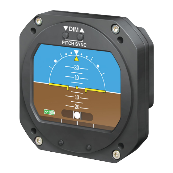
Page 7: Display Features
RCA2610-P Series Installation/Operation Guide KELLY MANUFACTURING COMPANY 1.3 DISPLAY FEATURES See Figure 1.2 below for typical display features. RCA2610-3P shown. 1 ROLL POINTER 2 ROLL DIAL PITCH DIAL PITCH SYNC SYMBOLIC 3 HORIZON LINE AIRPLANE 4 SLIP INDICATOR BATTERY 5 RATE OF TURN CHARGE INDICATOR Figure 1.3, Typical Display Features... -
Page 8: Standard Configurations
RCA2610-P Series Installation/Operation Guide KELLY MANUFACTURING COMPANY 1.4 STANDARD CONFIGURATIONS For all available options and configurations, refer to Table 1.2, below and Appendix C in back of manual. Panel Tilt Angle setting Set to customer requirements Mating Connector MS3116E8-4S or equivalent Color Scheme Standard Blue & Brown Display pointer style Fixed Power Failure Indication Flag All models Brightness Adjust All models Table 1.2, Standard Configurations... -
Page 9: Installation
RCA2610-P Series Installation/Operation Guide KELLY MANUFACTURING COMPANY SECTION 2, INSTALLATION 2.1 GENERAL INFORMATION The conditions and test required for the TSO approval of this article are minimum performance standards. It is the responsibility of those installing this article either on or within a specific type or class of aircraft to determine that the aircraft installation conditions are within the TSO standards. TSO articles must have a separate approval for installation in an aircraft. The article may be installed only if performed under 14CFR Part 43 or the applicable airworthiness requirements. -
Page 10: Operation
RCA2610-P Series Installation/Operation Guide KELLY MANUFACTURING COMPANY SECTION 3, OPERATION GUIDE 3.1 PRE-FLIGHT PROCEDURES During pre-flight procedures, the instrument must be provided with adequate electrical power under normal vibration conditions (engine running). A red “X” appears across the screen indicating that the instrument is booting up. When the X disappears, the instrument is ready. The startup process should be completed within three minutes. When applicable, check that the Battery Charge Status Indicator displays at least 50% charge to ensure a minimum of 30 minutes of battery operation in the event of a power failure. -
Page 11: In-Flight Procedures - Dimmer
RCA2610-P Series Installation/Operation Guide KELLY MANUFACTURING COMPANY 3.3 IN-FLIGHT PROCEDURES - DIMMER On startup, the RCA2610-P defaults at its maximum brightness. You may adjust the screen brightness at any time by pressing the DIMMER PUSH BUTTONS (DIM). Press and hold the DIM (▼) or BRIGHTEN (▲) PUSH BUTTON until you reach the desired setting and release, or tap each button for incremental steps (See figure 3.2 for dimming controls). On non-Pitch Sync models (-G models), pressing both buttons simultaneously will reset the brightness to maximum. WARNING On Pitch Sync models, pressing both buttons simultaneously will turn the PITCH SYNC feature on (as shown by the PITCH SYNC ‘ON’ INDICATOR). Press both buttons again to turn the PITCH SYNC off if it is not... -
Page 12: General Information
RCA2610-P Series Installation/Operation Guide KELLY MANUFACTURING COMPANY SECTION 4, GENERAL INFORMATION 4.1 Flight Testing and Adjustments After flight testing and evaluation, additional calibration my be required depending on the user’s application. Communicate flight test data with Kelly Manufacturing Company to determine appropriate adjustments. 4.2 Instrument Care The most easily damaged part of your instrument is the screen. Special care should be taken when cleaning the screen to prevent scratches and other damage. -
Page 13: Battery Replacement
RCA2610-P Series Installation/Operation Guide KELLY MANUFACTURING COMPANY 4.4 BATTERY REPLACEMENT When the “Chk Batt” warning appears on the screen, it indicates that either the battery failed the capacity test, there was a prob- lem with the capacity test, or the battery is inoperable. Before replacing the battery, perform another capacity test by completing steps 6 through 9 to re-test the battery. -
Page 14: Frequently Asked Questions (Faqs)
RCA2610-P Series Installation/Operation Guide KELLY MANUFACTURING COMPANY 4.5 FREQUENTLY ASKED QUESTIONS How long should my Digital Horizon last? There isn’t a good answer for this question. There are no moving parts in the RCA2610-P so there isn’t anything to wear out. The RCA 2610 should give hundreds of hours of trouble free operation. -
Page 15: Appendix Ado-160G Environmental Qualification Form
RCA2610-P Series Installation/Operation Guide KELLY MANUFACTURING COMPANY APPENDIX A Environmental Qualification: DO-160G Environmental Qualification Form NOMENCLATURE: ELECTRIC DIGITAL HORIZON MODEL NUMBER: RCA2610-series TSO NUMBER: C4c & C113a MANUFACTURERS SPECIFICATIONS: STP 1501 Rev. A (12/20/2016) MANUFACTURER: Kelly Manufacturing Company ADDRESS: 555 S. Topeka, Wichita, KS 67202 REVISION &... -
Page 16: Appendix Binstructions For Air Worthiness
RCA2610-P Series Installation/Operation Guide KELLY MANUFACTURING COMPANY APPENDIX B Instructions for Continued Airworthiness Equipment/Model Number: RCA2610 Series Equipment Descrip�on: Electric Digital Horizon 1. Description This document describes the necessary maintenance requirements and instruc�ons necessary to ensure the con�nued airworthiness of aircra�/rotorcra� with the RCA2610 Electric Digital Horizon installed. 2. -
Page 17: Appendix Ctable Of Part Numbers
RCA2610-P Series Installation/Operation Guide KELLY MANUFACTURING COMPANY APPENDIX C Table of Part Numbers Part Number Size Op�onal Features TSO Cer�fica�ons 102-0403-04-05 3 inch Pitch Sync TSO-C4c, TSO-C113a 102-0403-04-07 3 inch none TSO-C4c, TSO-C113a 102-0403-04-13 3 inch Pitch Sync, Ba�ery TSO-C4c, TSO-C113a 102-0403-04-15 3 inch Ba�ery... - Page 18 KMC PUBLICATION NO. 1401-6 KELLY MANUFACTURING COMPANY 555 S. TOPEKA WICHITA, KANSAS 67202 WWW.KELLYMFG.COM...
Need help?
Do you have a question about the rc allen instruments RCA 2610-P Series and is the answer not in the manual?
Questions and answers