Table of Contents
Advertisement
Quick Links
MODEL ET8415CR
Installation and Setup Instructions
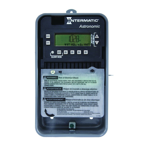
Description
This document explains the setup and configuration of the Intermatic ET8415 4-Circuit Electronic Astronomic
7-Day Time Switch. The ET8415 time switch automatically switches loads to a preset weekly schedule. The time
switch can support up to 28 fixed ON and 28 fixed OFF events (56 total) and up to four Astro events. Each event
can be applied to any combination of circuits and days.
The time switch features an LCD and panel-mounted control buttons to set, review, and monitor the time switch
functions, including enabling or disabling Daylight Saving Time (DST) and configuring DST switchover dates.
Follow these instructions to complete the installation and programming for the ET8415 time switch.
Federal Communications Commission (FCC) Notice for ET8415 Time Switch
This device complies with part 15 of the FCC rules. Operation of this device is subject to the following two conditions: (1) This device may
not cause harmful interference, and (2) This device must accept any interference, including interference that may cause undesired opera-
tion. This equipment has been tested and found to comply with the limits for a Class A digital device, pursuant to Part 15 of the FCC Rules.
These limits are designed to provide reasonable protection against harmful interference when the equipment is operated in a commercial
environment. This equipment generates, uses and radiates radio frequency energy and, if not installed and used in accordance with instruc-
tions, may cause harmful interference to radio communications. Operation of this equipment in a residential area is likely to cause harmful
interference that requires the user to correct at his or her own expense.
Installation
WARNING
•
Disconnect power at the circuit breaker(s) or disconnect switch(es) before installing or servicing.
•
More than one circuit breaker or disconnect switch may be required to de-energize the equipment before servicing.
•
Bonding between conduit connections is not automatic and must be provided as part of the installation.
•
Installation and/or wire must be in accordance with National and Local Electrical Code requirements.
•
Use #14 - #8 AWG wires, rated at least 90°C - COPPER conductors ONLY.
•
If the power disconnect point is out of sight, lock it in the OFF position and tag it to prevent unexpected application power.
•
Make sure there is not wire insulation under the terminal plate on the time switch connector. Firmly tighten terminal screws.
•
Replace plastic insulator covering terminals before powering ON.
•
KEEP DOOR CLOSED AT ALL TIMES when not servicing.
NOTICE
Do not touch the circuit board components. Contact with the circuit board components can create static discharge, which can damage the
microprocessor.
Follow these instructions to install the time switch.
1. Open the time switch enclosure door.
2. Press the catch at the top of the case and pull out the mechanism from the case.
3. Choose a knockout to remove from the enclosure.
NOTE: There are five 1/2 inch to 3/4 inch combination knockouts available. There are
two on the bottom of the enclosure, one on each side, and one on the rear.
4. Insert a flathead screwdriver into the slot of a 1/2 inch knockout and punch loose and
remove.
NOTE: If a 3/4 inch knockout is needed, remove the 1/2 inch knockout first, then the
outer ring. Smooth edge if necessary.
Risk of Fire or Electric Shock
Electronic 4 - Circuit Astronomic
7 - Day Time Switch
With Supercapacitor Carryover
Snap out catch
Snap out catch
Tilt top forward
Tilt top forward
Advertisement
Table of Contents

Related Manuals for Intermatic ET8415


Summary of Contents for Intermatic ET8415
- Page 1 This document explains the setup and configuration of the Intermatic ET8415 4-Circuit Electronic Astronomic 7-Day Time Switch. The ET8415 time switch automatically switches loads to a preset weekly schedule. The time switch can support up to 28 fixed ON and 28 fixed OFF events (56 total) and up to four Astro events. Each event can be applied to any combination of circuits and days.
- Page 2 5. Place the enclosure in the desired location, position at eye level, and provide space for the enclosure door to swing open fully. [219] [83] [145] In [mm] 6. Drill the holes and then clean out each hole. 7. Insert plastic anchors into the holes, if needed. IMPORTANT: If you are bringing power wires and wires for connecting applications through the back of the enclosure, connect the wires before mounting the enclosure.
- Page 3 Programming Overview Press MODE to scroll through the menus and program the current date, time, Astro zone, Astro events, and fixed events. Press + or - to configure the first part of a setting, such as MONTH. Press the ENTER/NEXT button to move to the next part of the setting, such as YEAR, and then press MODE to exit and move to the next menu.
- Page 4 Take one of these actions. If you select... Then... US2007 or MX1986, Go to step 10. Custom, Press ENTER/NEXT. The screen displays a flashing MAR and 2ND. Go to step 6. Press + or - to select a starting month for customized DST and press ENTER/NEXT. Press + or - to select a starting week (1st, 2nd, 3rd, 4th, or LST) and press ENTER/NEXT.
- Page 5 Setting Sunup and Sunset Times Multiple sunrise and sunset offsets can be configured for different areas in a facility. For example, a user can configure a sunrise offset for the lights in a parking lot to turn off one hour after normal sunrise. Follow this procedure to set sunup and sunset times.
- Page 6 Setting Fixed Timed Events Access the Fixed ON/OFF screen to set fixed switching times. Odd-numbered events are for ON switching and even-numbered events are for OFF switching. Follow these steps to set fixed time events. 1. Press MODE to scroll until SET FIXED ON@ appears on the screen. 2.
- Page 7 Resetting the Time Switch To perform a reset, press the reset button. The following occurs: • All display segments activate for one second, then the timer model number appears, followed by the firmware revision. • The current operational mode setting appears for the first two relays, followed by the current setting for the last two relays. •...
- Page 8 STATES DO NOT ALLOW LIMITATIONS ON THE DURATION OF AN IMPLIED WARRANTY, SO THE ABOVE LIMITATION MAY NOT APPLY TO YOU. This warranty service is available by either (a) returning the product to the dealer from whom the unit was purchased or (b) completing a warranty claim online at www.intermatic.com. This warranty is made by: Intermatic Incorporated, Customer Service 7777 Winn Rd., Spring Grove, Illinois 60081-9698.
Need help?
Do you have a question about the ET8415 and is the answer not in the manual?
Questions and answers