Table of Contents
Advertisement
Quick Links
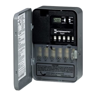
Electronic 7 - Day Time Switches
With 2 Independent Outputs and
Battery Powered Clock Operation
OWNER/INSTALLER INSTRUCTION MANUAL
ATTENTION: READ CAREFULLY BEFORE ATTEMPTING TO INSTALL YOUR INTERMATIC
TIME SWITCH. FAILURE TO COMPLY WITH INSTRUCTIONS COULD RESULT IN PERSONAL
INJURY AND/OR PROPERTY DAMAGE! RETAIN FOR FUTURE REFERENCE.
Description
The Intermatic Electronic 7-Day Time Switch automatically
switches 2 loads independently according to a preset weekly
schedule with to-the-minute accuracy. This time switch is
designed to directly switch resistive or inductive loads up to 30
amps at 24, 120 or 240 volts and to switch tungsten or ballast
loads up to the time switch rating. For use as a control timer in
applications requiring 7-day load control such as lighting,
heating, air conditioning systems, pumps, etcetera. Up to 20 (10
ON/10 OFF or any combination or 20 momentary pulse
operating) can be preset. These set points can be programmed
for any or all 7 days to provide for up to 140 set points or pulse
operations each week. Independent 2 load 7 day programming
provides complete flexibility for applications where load switching
differs each day of the week. The program can be overridden by
selecting the MANUAL position.
®
AM
ON
5:20
ET270 SERIES
INCLUDING MODELS:
ET279C (SPST each output)
Specifications
CLOCK VOLTAGE: 120 V.A.C., 60 Hz.
POWER CONSUMPTION: 5.0 Watts Max.
CONTACT CONFIGURATION: SPST for output 1 and 2
SWITCH RATING: (Per Pole)
•
30 Amps Inductive/Resistive, 24/120/240 V.A.C., 60 Hz.
•
20 Amps Resistive - 28 V.D.C.,
•
1 H.P. 120 V.A.C., 60 Hz.
•
2 H.P. 240 V.A.C., 60 Hz.
•
5 Amps Tungsten, 120/240 V.A.C., 60 Hz.
•
20 Amps Ballast 277 V.A.C., 60 Hz.
SET POINTS (EVENTS): 20 total for both outputs combined in
any combination (10 ON/10 OFF or any combination or 20
momentary pulse operations) daily.
Up to 140 (70 ON/70 OFF or any combination or 140 pulse
operations) weekly.
BATTERY POWERED CLOCK OPERATION: 3 Years minimum
(AA industrial grade alkaline supplied with time switch)
MIN. "ON" or "OFF" TIME: 1 minute.
MAX. "ON" or "OFF" TIME: 6 days 23 hours 59 minutes.
SHIPPING WEIGHT: 2..5 Lbs. (1.1 Kg)
CASE: Drawn steel; 7-3/4" (19.7 cm) high, 5" (12.7 cm)
wide, 3" (7.6 cm) deep; gray finish w/lockable spring hasp.
KNOCKOUTS: Combination 1/2 - 3/4" (one on back and
each side, two on bottom).
WIRE SIZE: AWG #10 through #18.
General Safety Information
WARNING:
Disconnect
all
servicing
this
time
switch
1.Follow all local electrical and safety codes, National
Electric Code (NEC), as well as Occupational Safety and
Health Act (OSHA).
2. If the power disconnect point is out of sight, lock it in the "OFF"
position and tag it to prevent unexpected application of power.
3. This time switch case must be grounded.
4. Do not exceed the maximum current carrying capacity of this
time switch.
5. Always replace the plastic insulator covering the terminal
before turning power "ON".
Installation
WARNING: DISCONNECT THE POWER TO THE TIME
SWITCH AND THE LOADS BEFORE INSTALLING THIS TIME
SWITCH.
1. Mount the time switch in the desired location using the three
mounting holes which are provided. Mount the time switch at
eye level, if possible, providing sufficient room to the left of the
120V Supply
power
before
installing
or
its
connected
loads.
or
Advertisement
Table of Contents

Related Manuals for Intermatic ET279C


Summary of Contents for Intermatic ET279C
-
Page 1: Specifications
With 2 Independent Outputs and Battery Powered Clock Operation OWNER/INSTALLER INSTRUCTION MANUAL ATTENTION: READ CAREFULLY BEFORE ATTEMPTING TO INSTALL YOUR INTERMATIC TIME SWITCH. FAILURE TO COMPLY WITH INSTRUCTIONS COULD RESULT IN PERSONAL INJURY AND/OR PROPERTY DAMAGE! RETAIN FOR FUTURE REFERENCE. - Page 2 enclosure for the cover to swing open fully. (See Figure #1 and Figure #2). The time switch mechanism does not need to be removed from the enclosure to mount the time switch since the top mounting hole is a slotted type mounting hole. Secure a screw or other fastener at eye level.
- Page 3 SWITCHING “ON” OR “OFF” SUN. MON. EVENT TIMES OPERATION Programming Steps Refer to programming instructions in this manual or the abbreviated instructions on time switch door label and note the following: • The slide switch located on the right side is used to select automatic operation (AUTO), manual operation (MANUAL) or to select programming (PROGRAM).
-
Page 4: Trouble Shooting
If within one (1) year from date of purchase, this product fails due to a defect in material or workmanship, Intermatic Incorporated will repair or replace, at its sole option, the unit free of charge. This warranty applies only to the original purchaser and is not transferable.
Need help?
Do you have a question about the ET279C and is the answer not in the manual?
Questions and answers