Advertisement
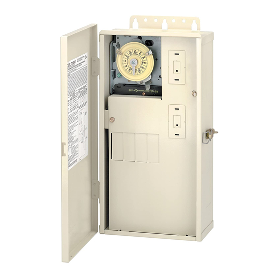
MODEL: T21004R
IN RAINPROOF (TYPE 3R) ENCLOSURE FOR INDOOR/OUTDOOR USE
60 AMP 120/240 VOLT OR 120/208 VOLT SINGLE PHASE, (THREE WIRE) AC
SUITABLE FOR SWIMMING POOL / SPA APPLICATIONS AND FOR DIRECT CONDUIT CONNECTION TO A WET-NICHE OR NO NICHE LUMINAIRE.
IMPORTANT:
The short circuit rating of this panel is 10000 symmetrical amperes.
680) or Canadian Electrical Code (including section 68) and local code requirements. This installation is subject to the approval
by the local inspection authority. The main lugs and neutral main are suitable for No. 14 to 2 AWG COPPER conductors. Use
No. 14 to 6 AWG COPPER conductors for branch circuit wiring. Follow gauge selection table and corresponding terminal screw
tightening torque requirements below. Install interchangeable circuit breakers with an interrupting current rating of 10000
symmetrical amperes, or higher. All circuit breakers in this control panel shall be of the same manufacturer and type. See list of
suitable types below. Follow manufacturers instructions for installing and testing of ground fault circuit breakers (GFCB) and
interrupters (GFCI). Install only LISTED receptacle(s) and/or wiring device(s) inside the enclosure. A LISTED wiring device may
be installed in the rectangular side knockout provided. When panel is outdoors, a LISTED rainproof cover must be installed over
the wiring device in the side knockouts. If this enclosure is used for direct conduit connection to a wet-niche or no niche
luminaire, one of the connection kits listed below in Note 5 must be used. This control should not be connected to any
equipment which would cause bodily injury or property damage should it be activated unexpectedly. After wiring, install front
panel over wiring compartment and close unused breaker openings with filler plates. KEEP DOOR CLOSED AT ALL TIMES.
SUITABLE LISTED BREAKERS
MANUFACTURER
SINGLE DOUBLE TWIN QUAD
CUTLER-HAMMER
BR
MURRY
MP-T
SIEMENS
QP
SQUARE D
HOM
THOMAS & BETTS
TB
NOTES:
1. Any Intermatic T100M or ET100CM series Time Switch, PF1000M
Series freeze protection or RC2000M Series air switch mechanism
may be installed in the bracket provided or in the event an existing
mechanism is replaced.
2. If this control panel requires bonding, attach a LISTED bonding
terminal of a suitable size using the mounting hole(s) provided on the
bottom of the enclosure (156T11047A may be ordered).
3. When a back-fed breaker is used in this control panel, order
22T904A to comply with NEC article 384-16 (g).
4. Wiring devices may be installed in this control panel (order 21T156A
(4) Standoffs for mounting).
5. The following kits are available to connect under water luminaires to this
enclosure:
1/2" non-metallic - order 156PA13713A
3/4" non-metallic - order 156PA13714A
1" non-metallic - order 156PA13715A
1/2" metallic - order 156PA14336A
TIME SWITCH RATINGS:
30 AMP. RESISTIVE, INDUCTIVE, TUNGSTEN OR 1000 VA PILOT DUTY -
120/208/240 VOLT A.C. 2 HP (24 FLA)-120 VOLT A.C.,
5 HP (28 FLA)-240 VOLT A.C.
CLOCK MOTOR: 208-277 VOLTS 60 HZ.
(To order clock motor replacement, specify part no. WG--on motor cover)
TIME SWITCH OPERATING INSTRUCTIONS
1. TO SET "ON" AND "OFF" TIMES:
Hold TRIPPERS against edge of CLOCK-DIAL, pointing to time (AM or PM)
when ON and OFF operations are desired. Tighten tripper screws firmly.
2. TO SET TIME-OF-DAY:
TIME
Pull CLOCK-DIAL outward. Turn in either direction
POINTER
and align the exact time-of-day on the CLOCK-DIAL
ON
(the time now, when switch is being put into opera-
TIME
TRIPPER
DIAL
tion) to the pointer.
• TO OPERATE SWITCH MANUALLY: Move MAN-
OFF
UAL-LEVER below left or right as indicated by
TRIPPER
arrows. This will not affect the next operation.
MANUAL
LEVER
• FOR MORE THAN ONE DAILY ON-OFF OPER-
ATION: Place additional tripper pairs on CLOCK-DIAL (order 156T1978A).
• IN CASE OF POWER FAILURE: Reset CLOCK-DIAL to proper time of day.
See step 2 above.
This control panel must be installed according to the National Electrical Code (including article
CIRCUIT BREAKER
BR
BRD
BRD
MP-T
MH-T MH-T
QP
QT
QT
HOM
HOMT HOMT
TB
TBBD TBBQ
-DO NOT MOVE POINTER-
CLASS CTL DISTRIBUTION /CONTROL
PANEL WITH TIME SWITCH
FILLER
PLATE
GFCB
WIRE SIZE CIRCUIT NEUTRAL NEUTRAL (CONTINUOUS CIRCUIT MAXIMUM
GFCB
BRFP
75˚C MIN BREAKER
MP-GT LX100FP
INSULATION RATING
QPF
QF3
AWG
14
----
HOMFP
12
GFB
FP-1C-TB
10
8
6
*
TORQUE CIRCUIT BREAKER LUGS TO VALUES SPECIFIED ON
CIRCUIT BREAKERS
I I N N T T E E R R M
SPRING GROVE ILLINOIS 60081-9698 158TP12178
WIRING INFORMATION - COPPER CONDUCTORS ONLY
TERMINAL TORQUE*
MAX MOTOR PURPOSE BRANCH
SUPPLY LINE AND
LOAD
MAIN
AND
DUTY)
LUGS
GROUND 120V. 240V.
AMP
LB-IN
LB-IN
HP
15
35
20
1/2
20
35
20
1
30
35
20
1 1/2
50
40
25
2
60
45
35
---
M A A T T I I C C I I N N C C O O R R P P O O R R A A T T E E D D
LR3730
UL 508
UL1563
GENERAL
GENERAL PURPOSE
BRANCH
CIRCUIT
BREAKER CURRENT
RATING
CAPACITY
HP
AMP
AMP
1
15
12
2
20
16
3
30
24
5
40
32
---
60
44
Advertisement
Table of Contents


Need help?
Do you have a question about the T21004R and is the answer not in the manual?
Questions and answers