Tripp Lite PDU40TDUAL Owner's Manual
Zero u dual independent power circuit
Hide thumbs
Also See for PDU40TDUAL:
- Owner's manual (16 pages) ,
- Technical application bulletin (8 pages) ,
- Owner's manual (8 pages)
Advertisement
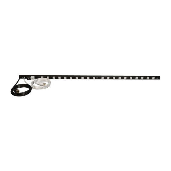
PDU40TDUAL
Zero U Dual Independent Power Circuit
Power Distribution Unit (PDU)
Important Safety Instructions
SAVE THESE INSTRUCTIONS
This manual contains instructions and warnings that should be followed
during the installation, operation, and storage of this product. Failure to
heed these instructions and warnings will void the product warranty.
Important Warnings
• The PDU provides convenient multiple outlets distributed across two independent power circuits, but it
DOES NOT provide surge or line noise protection for connected equipment.
• The PDU is designed for indoor use only in a controlled environment away from excess moisture,
temperature extremes, conductive contaminants, dust or direct sunlight.
• Do not connect the PDU to an ungrounded outlet or extension cords or adapters that eliminate the
connection to ground.
• The power requirement for each piece of equipment connected to the PDU must not exceed the
individual outlet's load rating.
• The total power requirement for equipment connected to each of the two independent power circuits
must not exceed the maximum load rating for that circuit.
• Do not drill into or attempt to open any part of the PDU housing. There are no user-serviceable parts inside.
• Do not attempt to modify the PDU, including the input plugs and power cables.
• Do not attempt to use the PDU if any part of it becomes damaged.
• Do not attempt to mount the PDU to an insecure or unstable surface.
• Never attempt to install electrical equipment during a thunderstorm.
• Use of this equipment in life support applications where failure of this equipment can reasonably be
expected to cause the failure of the life support equipment or to significantly affect its safety or
effectiveness is not recommended. Do not use this equipment in the presence of a flammable
anesthetic mixture with air, oxygen or nitrous oxide.
Installation
1B
1A
1C
1A
Zero U Rack Configuration (Mounting Clips). Attach the three mounting clips supplied with the PDU
to the rack enclosure using the included hardware. The mounting clips should be attached along a
vertical plane at equidistant points which approximately correspond to the center and ends of the PDU.
The exact mounting configuration may vary depending on the rack and enclosure. If possible, use pre-
existing mounting points within the enclosure. Using an assistant, place a rear corner of the PDU at an
inside edge of the mounting clips, pivot the PDU toward the alternate inside edge and snap into place.
1B
Zero U Rack Configuration (Mounting Buttons). To mount the PDU with the outlets facing inward,
align the mounting buttons on the rear of the PDU with the rack mounting slots and slide the PDU
into position. To mount the PDU with the outlets facing the rear of the rack enclosure, remove and
discard each of the screws that attach the mounting buttons to the PDU*. Attach each mounting
button to a mounting bracket using the included M3 screws, and then attach each mounting bracket
to the rear of the PDU (1 at the top, 1 at the middle, and 1 at the base) using the included M4
screws (where the mounting button would otherwise be placed). Position the PDU as desired in the
rack enclosure, align the buttons with the rack mounting slots, and slide the PDU into position.
* Three M3 screws are included with the mounting hardware and should be used to attach the
mounting button to the mounting bracket. The screw that was initially used to attach the mounting
button to the PDU should not be used to attach the mounting button to the mounting bracket or to
attach the mounting bracket to the PDU.
PDU40TDUAL
Unidad de distribución de potencia (PDU) con
Circuito de potencia dual independiente de cero U
Instrucciones de seguridad importantes
GUARDE ESTAS INSTRUCCIONES
Este manual contiene instrucciones y advertencias que deben seguirse
durante la instalación, operación y almacenamiento de este producto.
De no seguirlas, se anulará la garantía del producto.
Advertencias importantes
• La PDU proporciona cómodas salidas múltiples distribuidas a través de dos circuitos de potencia
independientes, pero NO proporciona protección contra sobretensión o ruido en la línea al equipo
conectado.
• La PDU está diseñada sólo para empleo en interiores en un ambiente controlado, lejos del exceso de
humedad, temperaturas extremas, contaminantes conductores, polvo o luz solar directa.
• No conecte la PDU a una salida sin conexión a tierra ni a cables de extensión o adaptadores que
eliminen la conexión a tierra.
• El requisito de potencia de cada equipo conectado a la PDU no debe exceder la capacidad de carga
individual de la salida.
• El requisito de potencia total para el equipo conectado a cada uno de los dos circuitos de potencia
independientes no debe exceder la máxima capacidad de carga para dicho circuito.
• No taladre ni trate de abrir ninguna parte de la cubierta de la PDU. No hay partes en su interior que
requieran mantenimiento por parte del usuario.
• No intente modificar la PDU, incluyendo los enchufes de entrada y los cables de alimentación.
• No intente usar la PDU si alguno de sus componentes está dañado.
• No intente montar la PDU en una superficie insegura o inestable.
• Nunca intente instalar equipos eléctricos durante una tormenta eléctrica.
• El uso de este equipo en aplicaciones de soporte de vida en donde la falla de este equipo pueda
razonablemente hacer suponer que causará fallas en el equipo de soporte de vida o afecte
significativamente su seguridad o efectividad, no está recomendado. No use este equipo en la
presencia de una mezcla anestésica inflamable con aire, oxigeno u óxido nitroso.
201105056 93-2533.indd 1
Owner's Manual
4
2
3
Copyright © 2011 Tripp Lite. All rights reserved.
Manual del propietario
Installation
(Continued)
1C
Wall or Under-Counter Configuration. Attach the three mounting clips supplied with the PDU to a
wall or similar flat, secure surface using the included hardware. The mounting clips should be
attached along a vertical or horizontal plane at equidistant points which approximately correspond
to the center and ends of the PDU. If possible, use pre-existing mounting points. Using an assistant,
place a rear corner of the PDU at an inside edge of the mounting clips, pivot the PDU toward the
alternate inside edge and snap into place. WARNING: Do not attempt to mount the PDU with
the outlets facing downward; the mounting clips are not designed to support the weight of
the PDU in that manner.
Note: Regardless of configuration, the user must determine the fitness of hardware and procedures
before mounting. The PDU and included hardware are designed for common rack and rack enclosure
types and may not be appropriate for all applications.
2
Attach each input plug of the PDU to a grounded outlet. The input plugs, power cords, breakers
and outlets are color-coded in black and gray to correspond to the two independent power circuits.
WARNING: Attach each input plug to a separate power circuit. Consult with the electrician
at the installation site if necessary.
3
Attach equipment to the PDU. Do not exceed the load rating for each circuit; distribute equipment
appropriately between the two circuits to obtain the maximum utility from the PDU.
4
Optional Installation. The PDU includes two adapters that convert the L5-20P input plugs to 5-20P
input plugs. Use both adapters, a single adapter or neither of the adapters. The adapters are optional;
the PDU will work properly without connecting the adapters. The adapters are not color-coded.
Features
1
2
1
NEMA L5-20P Input Plugs: The input plugs and associated power cords are color-coded to
correspond with each of the independent power circuits.
2
NEMA 5-20P Plug Adapters: The adapters convert the input plugs from NEMA L5-20P to NEMA
5-20P . The adapters are not color-coded.
3
Circuit Breakers: If the current drawn by the equipment connected to the corresponding independent power
circuit exceeds that circuit's Maximum Load Rating for longer than a few seconds, a circuit breaker will trip to
prevent possible damage. When a circuit breaker trips, its plunger will pop up. Disconnect excess equipment
from the affected circuit and allow the breaker to cool one minute before depressing the plunger to reset the
breaker. The circuit breakers are color-coded to correspond with each of the independent power circuits.
4
NEMA 5-15/20R Outlets: The outlets are color-coded to correspond with each of the independent
power circuits.
Limited Lifetime Warranty
Seller warrants this product, if used in accordance with all applicable instructions, to be free from original
defects in material and workmanship for its lifetime. If the product should prove defective in material or
workmanship within that period, Seller will repair or replace the product, at its sole discretion. Service
under this Warranty can only be obtained by Buyer delivering or shipping the product (with all shipping or
delivery charges prepaid) to: Tripp Lite, 1111 W. 35th Street, Chicago, IL 60609. Seller will pay return
shipping charges. Call Tripp Lite at (773) 869-1234 before sending any equipment back for repair.
THIS WARRANTY DOES NOT APPLY TO NORMAL WEAR OR TO DAMAGE RESULTING FROM ACCIDENT,
MISUSE, ABUSE OR NEGLECT. SELLER MAKES NO EXPRESS WARRANTIES OTHER THAN THE WARRANTY
EXPRESSLY SET FORTH HEREIN. EXCEPT TO THE EXTENT PROHIBITED BY APPLICABLE LAW, ALL IMPLIED
WARRANTIES, INCLUDING ALL WARRANTIES OF MERCHANTABILITY OR FITNESS, ARE LIMITED IN
DURATION TO THE WARRANTY PERIOD SET FORTH ABOVE; THIS WARRANTY EXPRESSLY EXCLUDES ALL
INCIDENTAL AND CONSEQUENTIAL DAMAGES. (Some states do not allow limitations on how long an
implied warranty lasts, and some states do not allow the exclusion or limitation of incidental or
consequential damages, so the above limitations or exclusions may not apply to you. This Warranty gives
you specific legal rights, and you may have other rights which vary from jurisdiction to jurisdiction).
WARNING: The individual user should take care to determine prior to use whether this device is suitable, adequate
or safe for the use intended. Since individual applications are subject to great variation, the manufacturer makes
no representation or warranty as to the suitability or fitness of these devices for any specific application.
WARRANTY REGISTRATION
Visit www.tripplite.com/warranty today to register the warranty for your new Tripp Lite product. You'll be automatically
entered into a drawing for a chance to win a FREE Tripp Lite product!*
* No purchase necessary. Void where prohibited. Some restrictions apply. See website for details.
Regulatory Compliance Identification Numbers
For the purpose of regulatory compliance certifications and identification, your Tripp Lite product has been assigned a
unique series number. The series number can be found on the product nameplate label, along with all required approval
markings and information. When requesting compliance information for this product, always refer to the series number.
The series number should not be confused with the marking name or model number of the product.
The policy of Tripp Lite is one of continuous improvement. Specifications are subject to change without notice.
Made in China.
Instalación
1B
1A
1C
1A
Configuración del rack (bastidor) de cero U (Sujetadores de Montaje). Fije los tres sujetadores
de montaje suministrados con la PDU a la caja del rack (bastidor) usando los materiales incluidos.
Los sujetadores de montaje deben fijarse a lo largo de un plano vertical en puntos equidistantes que
correspondan aproximadamente al centro y los extremos de la PDU. La exacta configuración de
montaje puede variar dependiendo del rack (bastidor) y la caja. Si es posible, use puntos de montaje
previamente existentes dentro de la caja. Con la ayuda de otra persona, coloque una esquina
posterior de la PDU en un borde interior de los sujetadores de montaje, gire la PDU hacia el borde
interior opuesto y colóquela a presión en su posición.
1B
Configuración para Rack en Cero U (Botones de Instalación). Para instalar el PDU con los
tomacorrientes viendo hacia adentro, alinee los botones de Instalación en la parte posterior del PDU con
las ranuras de Instalación del rack y deslice el PDU a su posición. Para instalar el PDU con los
tomacorrientes viendo hacia la parte posterior del gabinete del rack, quite y deseche cada uno de los
tornillos que sujetan los botones de Instalación del PDU*. Acople cada botón de Instalación a un soporte
de instalación usando los tornillos M3 incluidos y entonces, acople cada soporte de instalación a la parte
posterior del PDU (1 en la parte superior, 1 al centro y 1 en la base) usando los tornillos M4 incluidos (en
donde el botón de Instalación debería colocarse). Coloque el PDU como se desea en el gabinete del rack,
alinee los botones con las ranuras de Instalación del rack y deslice el PDU a su posición.
1111 W. 35th Street • Chicago, IL 60609 USA
(773) 869-1234 • www.tripplite.com
3
4
1111 W. 35th Street • Chicago, IL 60609 USA
(773) 869-1234 • www.tripplite.com
2
4
3
5/19/2011 9:07:19 AM
Advertisement
Table of Contents

Related Manuals for Tripp Lite PDU40TDUAL


Summary of Contents for Tripp Lite PDU40TDUAL
- Page 1 Warranty can only be obtained by Buyer delivering or shipping the product (with all shipping or delivery charges prepaid) to: Tripp Lite, 1111 W. 35th Street, Chicago, IL 60609. Seller will pay return Zero U Rack Configuration (Mounting Clips). Attach the three mounting clips supplied with the PDU shipping charges.
- Page 2 2. TRIPP LITE, se compromete a reparar, y en caso de que a su juicio no sea posible la reparación, a cambiar el equipo, así como las piezas y componentes defectuosos del mismo sin cargo alguno para el propietario durante el periodo de garantía, así...
Need help?
Do you have a question about the PDU40TDUAL and is the answer not in the manual?
Questions and answers