Table of Contents
Advertisement
Quick Links
Advertisement
Table of Contents

Related Manuals for ANTAIRA STE-708 Series


Summary of Contents for ANTAIRA STE-708 Series
- Page 1 Antaira Industrial Serial Device Server Series STE-7xx Series User Manual V 1.0 STE-708 & STE-716 Series 1U 19” Rackmount Industrial Serial Device Servers 8/16-Port Industrial RS232 and RS422/485 Serial Device Servers with Dual LAN User Manual Version 1.0...
- Page 2 Trademark Information Antaira is a registered trademark of Antaira Technologies, LLC, Microsoft Windows and the Windows logo are the trademarks of Microsoft Corp. NetWare is the registered trademark of Novell Inc. WMM and WPA are the registered trademarks of Wi-Fi Alliance.
- Page 3 STE-708A, STE-708A-EU STE-716A, STE-716A-EU STE-708A-48VDC STE-716A-48VDC STE-708Bi, STE-708Bi-EU STE-716Bi, STE-716Bi-EU STE-708Bi-48VDC STE-716Bi-48VDC This document is the current official release manual. Please check our website (www.antaira.com) for any updated manual or contact us by e-mail (support@antaira.com).
-
Page 4: Table Of Contents
Industrial Serial Device Server Series STE-7xx Series User Manual V 1.0 Table of Contents Preface ........................... 1 Overview ........................2 Product Overview ..........................2 Key Features ............................2 Getting Started ......................3 Model Comparison ..........................3 Inside the Package ..........................3 Panel Layout &... - Page 5 Industrial Serial Device Server Series STE-7xx Series User Manual V 1.0 5.5.3 E-mail Settings ......................... 25 Log Settings ............................27 5.6.1 System Log Settings......................... 27 5.6.2 COM Log Settings ........................27 5.6.3 Event Log ..........................28 5.6.4 COM Data Log .......................... 29 System Setup ............................
- Page 6 Industrial Serial Device Server Series STE-7xx Series User Manual V 1.0 Alert Settings ............................ 47 6.7.1 Configuring E-mail ........................47 6.7.2 Configuring Alert Event ......................48 System Configuration ........................49 6.8.1 Link State ..........................49 6.8.2 Time Settings ..........................50 6.8.3 Security Settings ........................
- Page 7 Industrial Serial Device Server Series STE-7xx Series User Manual V 1.0 8.2.4 Exceptions ..........................77 Using Serial/IP Port Monitor ......................83 8.3.1 Opening the Port Monitor ......................83 8.3.2 The Activity Panel ........................83 8.3.3 The Trace Panel ........................84 8.3.4 Serial/IP Advanced Settings ....................
-
Page 8: Preface
For any related problems, please contact Antaira Technologies for further assistance at (844) 268-2472. Supported Platform This manual is designed for the Antaira Technologies’ STE-708 & STE-716 series and that model only. Warranty Period 5-year limited warranty... -
Page 9: Overview
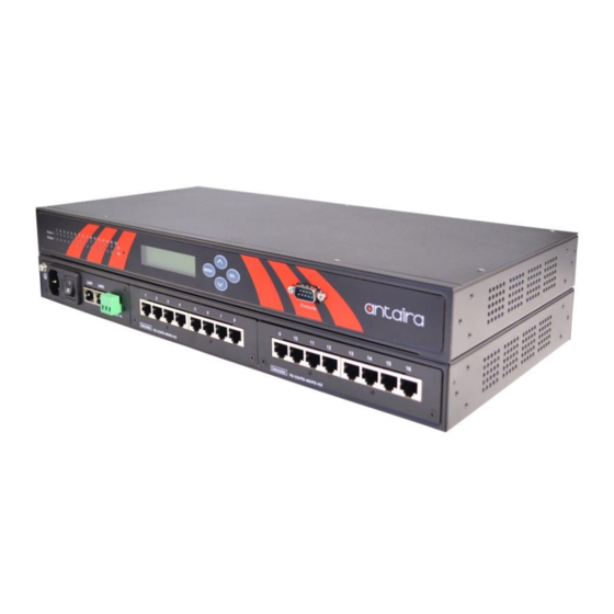
Overview 2.1 Product Overview Antaira Technologies’ new STE-708 and STE-716 series is either an 8 or 16-port industrial 1U 19” rackmount designed as an RS232 or RS422/485 serial device server. Each unit is built with dual LAN ports which allow users to set up a ring topology network for dual data redundancy applications. -
Page 10: Getting Started
Industrial Serial Device Server Series STE-7xx Series User Manual V 1.0 Getting Started 3.1 Model Comparison Model Description STE-708A 8-Port 1U Rackmount Industrial RS232 Serial Device Server, AC Input, US Plug STE-708A-EU 8-Port 1U Rackmount Industrial RS232 Serial Device Server, AC Input, EU Plug STE-708A-DC 8-Port 1U Rackmount Industrial RS232 Serial Device Server, DC Input, US Plug STE-708Bi... -
Page 11: Panel Layout & Dimensions
Please do not attempt to manipulate the product in any way, if users are unsure of the steps described here, please contact Antaira Technologies’ technical support team at (844)268-2472 or contact the local sales channel for immediate assistance. -
Page 12: User Interface Overview
STE-7xx Series User Manual V 1.0 3.5 User Interface Overview Antaira Technologies’ STE-708 and 716 series are designed as a device that is capable of transmitting data between serial and Ethernet. The device’s user interface is designed intuitively for ease of use to suit the customer’s needs. The web configuration appears as follows in Figure 3.2. -
Page 13: Factory Default Settings
Industrial Serial Device Server Series STE-7xx Series User Manual V 1.0 3.6 Factory Default Settings All brand new STE-708 and 716 series will be set with factory default settings (Figure 3.3). Parameters Default Values IP Address 10.0.50.100 LAN 1 Gateway 10.0.0.254 Subnet Mask 255.255.0.0... -
Page 14: Lcm Configuration
Industrial Serial Device Server Series STE-7xx Series User Manual V 1.0 LCM Configuration A Liquid Crystal Monitor (LCM) is installed on the front panel of the device that can be used to display device information and perform basic configurations. Below, (Figure 4.1) illustrates its buttons and corresponding functions. -
Page 15: Overview
Industrial Serial Device Server Series STE-7xx Series User Manual V 1.0 4.2.1 Overview Layer Layer Layer Layer Layer Description 1.Model Name Display Model Name 2.Kenrnel ver. Display Kernel Version 3.AP ver. Display AP Version 1.Overview 1.LAN status Display LAN 1 Status 4.LAN 1 2.MAC Display MAC Address of LAN 1... -
Page 16: Serial Settings
Industrial Serial Device Server Series STE-7xx Series User Manual V 1.0 4.2.3 Serial Settings Layer Layer Layer Layer Layer Description 1.Select Select a COM Port to Configure Port 1.300 2.600 3.1200 4.2400 5.4800 6.9600 1.Baud Rate 7.19200 Display/Change Baud Rate 8.38400 9.57600 10.115200... - Page 17 Industrial Serial Device Server Series STE-7xx Series User Manual V 1.0 character mode and set the Character 1.Disable Disable UART Delimiter 1.Timer: Change UART delimiter 2.Serial to to timer mode and set its time 6.Delimiter 2.Enable 2.Char: Change UART delimiter to character mode and set the Character Display/Change UART Mode to...
-
Page 18: Server State
Industrial Serial Device Server Series STE-7xx Series User Manual V 1.0 2.Dest IP 1 Display/Change Destination IP 1 3.Dest Port 1 Display/Change Destination Port 1 1.Disable Disable Destination [2~16] 4.Destination Display/Change Destination IP [2~16] 2.Enable [2~16] and Destination port [2~16] 1.No Apply Link Mode settings to all 5.Apply to all... -
Page 19: Web Configuration
Industrial Serial Device Server Series STE-7xx Series User Manual V 1.0 Web Configuration 5.1 Administrator Login As soon as the device is connected on the LAN, the user can proceed to navigate through its configuration using Serial Manager (utility that comes with the product CD), shown below in Figure 5.1 (displaying the IP, MAC address, etc). -
Page 20: Overview
Industrial Serial Device Server Series STE-7xx Series User Manual V 1.0 5.2 Overview This section gives general status information for the device, network, ERPS and STP. Figure 5.2 – General Information Device Information: Displays the system’s name and the Kernel/AP versions. Figure 5.3 –... - Page 21 Industrial Serial Device Server Series STE-7xx Series User Manual V 1.0 Ethernet Ring Protection Switch (ERPS) Information: Displays the ‘Ring’ and ‘Port’ status. Figure 5.5 – ERPS Information Spanning Tree Information: Displays the current STP and STP Port settings and their status. Figure 5.6 –...
-
Page 22: Network Configuration
Industrial Serial Device Server Series STE-7xx Series User Manual V 1.0 5.3 Network Configuration Click on the “Network” link to open the network settings. LAN Mode Settings: Dual Subnet Mode Subnet is a logically visible subdivision of an IP network. The LAN 1 and LAN2 can be assigned to different subnets. - Page 23 Industrial Serial Device Server Series STE-7xx Series User Manual V 1.0 Figure 5.10 – LAN Mode Settings: Bridge Mode LAN Settings DHCP Alternatively, users may activate the Dynamic Host Configuration Protocol (DHCP) client function by checking on the “Obtain an IP automatically”...
- Page 24 A typical ring topology provides multipoint connectivity, but the network traffic will loop inside the ring without a proper protection mechanism. Antaira’s STE-708 / 716 series supports an Ethernet Ring Protection Switching (ERPS) protocol for Ethernet layer ring networks without requiring extra managed Ethernet switches.
- Page 25 Industrial Serial Device Server Series STE-7xx Series User Manual V 1.0 STP Settings: Standard Spanning Tree (STP) is supported by the IEEE standards. The STP function is to help prevent switching loops and ensuring broadcast radiation. STP creates a spanning tree and disables those redundant links that are on the same level of the tree, which leaves only a single active path between any two nodes.
- Page 26 Industrial Serial Device Server Series STE-7xx Series User Manual V 1.0 Figure 5.14 – Bridge Mode: Spanning Tree Settings...
-
Page 27: Serial Settings
Industrial Serial Device Server Series STE-7xx Series User Manual V 1.0 5.4 Serial Settings Click on the “Serial” link to open its submenu and COM1 settings. Figure 5.15 – Serial Port Settings... -
Page 28: Com Configuration
Industrial Serial Device Server Series STE-7xx Series User Manual V 1.0 5.4.1 COM Configuration This section will only focus on the serial settings as shown in Figure 5.16. Details on connectivity protocols and the settings will be described in Chapter 7 Link Modes and Applications. Figure 5.16 –... -
Page 29: Com Configuration: Advanced Settings
Industrial Serial Device Server Series STE-7xx Series User Manual V 1.0 5.4.2 COM Configuration: Advanced Settings Click on the “Advanced Settings” button to open the dialog (Figure 5.17). Figure 5.17 – COM Configuration - Advanced Settings TCP Timeout- Specifies the value in “TCP Timeout” to force the STE-708 / STE-716 series to actively close a TCP connection after a specific inactivity time limit (no packets). - Page 30 Industrial Serial Device Server Series STE-7xx Series User Manual V 1.0 Interval Timeout- The STE-708/STE-716 series will transmit the serial data in its buffer when the specified time interval has been reached and no more serial data comes in. The default value is calculated automatically based on the baud rate.
-
Page 31: Snmp/Alert Settings
Industrial Serial Device Server Series STE-7xx Series User Manual V 1.0 Serial Serial FIFO- The STE-718/STE-716 series has its FIFO function enabled to optimize its serial performance as default. In some applications (particularly when the flow control is enabled), it may deem necessary to disable the FIFO function to minimize the amount of data that is transmitted through the serial interface after a flow of events is triggered to reduce the possibility of overloading the buffer inside the serial device. -
Page 32: Alert Event
Industrial Serial Device Server Series STE-7xx Series User Manual V 1.0 5.5.2 Alert Event Events could be triggered in different ways. Various ways include: Cold Start, Warm Start, Authentication Failure, IP Change, Password Change, and Link Down. The STE-708/STE-716 series supports three different types of event alerts - E-mail, SNMP Trap, and Relay. - Page 33 Industrial Serial Device Server Series STE-7xx Series User Manual V 1.0 Figure 5.20 – E-mail Settings Attention It is also important to properly setup the default gateway and DNS servers in the network settings, so the STE-708/716 series can lookup DNS names and route the mails to the proper default gateway.
-
Page 34: Log Settings
Industrial Serial Device Server Series STE-7xx Series User Manual V 1.0 5.6 Log Settings The Syslog function is turned on by default and cannot be turned off. It is used to log the system events and report to an external Syslog server (if necessary). Also, transmitted data could be logged for recording or debugging purposes. -
Page 35: Event Log
Industrial Serial Device Server Series STE-7xx Series User Manual V 1.0 Note: The STE-708 / STE-716 series can internally store up to 1500 lines. A request or a response will consist of one line, data longer than 512 bytes will go into another line. -
Page 36: Com Data Log
Industrial Serial Device Server Series STE-7xx Series User Manual V 1.0 5.6.4 COM Data Log Users can select from the COMx dropdown box to display logs from different COM ports. The first three lines were set to show the logging of data length and the last two lines were set to show data content in Hexadecimal. -
Page 37: System Setup
Industrial Serial Device Server Series STE-7xx Series User Manual V 1.0 5.7 System Setup Click on the “System Setup” link to open its submenu and this will lead to the ‘Link State’. 5.7.1 Link and Serial State Link and Serial State display the information of each connection for all serial ports for debugging purposes. -
Page 38: Time Settings
Industrial Serial Device Server Series STE-7xx Series User Manual V 1.0 5.7.2 Time Settings Date and time can be set manually, or using Network Time Protocol (NTP) to automatically synchronize with a time server. For auto-synching, select NTP in the Time Setting field, then proceed to fill the IP address or host name for it. -
Page 39: Security Configuration
Industrial Serial Device Server Series STE-7xx Series User Manual V 1.0 5.7.3 Security Configuration Change Password The default password is null, users can change the password by filling in the new password to the new Password and verified password fields. Be aware that the password is case sensitive. Figure 5.27 –... -
Page 40: Backup And Restore Configuration
Industrial Serial Device Server Series STE-7xx Series User Manual V 1.0 5.7.4 Backup and Restore Configuration Users can backup and restore the current settings to the local computer (Figure 5.29). Figure 5.29 – Backup & Restore Configuration 5.7.5 Firmware Upgrade To upgrade the firmware, browse to the location of the new firmware binary file (.dld) and click the “Upload”... -
Page 41: Cli Configuration
CLI Configuration 6.1 Accessing the CLI Antaira’s STE-708/STE-716 series can be configured by Command-Line Interface (CLI). There are two ways to access the CLI, and both methods will lead to the same CLI, i.e., a command line interface that allows users to modify most settings in the device. -
Page 42: General Information
Industrial Serial Device Server Series STE-7xx Series User Manual V 1.0 Figure 6.1 6.2 General Information Open the command line interface (console terminal) and telnet to the device using its IP address. The default username is “admin” and password is empty (blank). A main menu should appear as below in Figure 6.2. -
Page 43: Lcm Configuration
Industrial Serial Device Server Series STE-7xx Series User Manual V 1.0 Notes: 1. The STE-708/STE-716 series will automatically close the telnet connection after 3 minutes of inactivity. 2. Press the “ESC” key to return to the previous menu. 3. Some changes to the device would take effect only after the device is restarted. 4. -
Page 44: Main Manual Structure
Industrial Serial Device Server Series STE-7xx Series User Manual V 1.0 6.4 Main Manual Structure Press the <Menu> key to enter the main menu. Press <Scroll Down> to go to the next layer or option. Press <Scroll Up> to go to the back one layer or option. 6.4.1 Overview Layer Layer... -
Page 45: Serial Settings
Industrial Serial Device Server Series STE-7xx Series User Manual V 1.0 6.4.3 Serial Settings Layer Layer Layer Layer Layer Description 1.Select Select a COM Port to configure Port 1.300 2.600 3.1200 4.2400 5.4800 6.9600 1.Baud Rate 7.19200 Display/Change Baud Rate 8.38400 9.57600 10.115200... - Page 46 Industrial Serial Device Server Series STE-7xx Series User Manual V 1.0 character mode and set the Character 1.Disable Disable UART Delimiter 1.Timer: Change UART delimiter 2.Serial to to timer mode and set its time 6.Delimiter 2.Enable 2.Char: Change UART delimiter to character mode and set the Character Display/Change UART Mode to...
-
Page 47: Server State
Industrial Serial Device Server Series STE-7xx Series User Manual V 1.0 2.Dest IP 1 Display/Change Destination IP 1 3.Dest Port 1 Display/Change Destination Port 1 1.Disable Disable Destination [2~16] 4.Destination Display/Change Destination IP [2~16] 2.Enable [2~16] and Destination port [2~16] 1.No Apply Link Mode settings to all 5.Apply to all... - Page 48 Industrial Serial Device Server Series STE-7xx Series User Manual V 1.0 This system overview window gives the general information on Ethernet, MAC address, kernel and AP version. Operation: Main → [1]Overview Figure 6.9...
-
Page 49: Networking Configuration
Industrial Serial Device Server Series STE-7xx Series User Manual V 1.0 6.5 Networking Configuration This section allows users to change an IP address, subnet mask, gateway, or SNMP information. Please note that the new settings will not take effect until the device is restarted. Operation: Main →... -
Page 50: Dns Settings
Operation: Main → [2] Networking → [3] DNS Settings Figure 6.12 6.5.3 SNMP Settings Antaira’s STE-708/STE-716 series allows the user to enable or disable the SNMP function. The changes will become effective immediately. Basic SNMP configurations such as Read/Write Community, SysName (System Name), SysLocation (System Location), SysContact (System Contact), and SNMP Trap Server IP are supported. -
Page 51: Redundancy Settings
Industrial Serial Device Server Series STE-7xx Series User Manual V 1.0 6.5.4 Redundancy Settings STE-708/STE-716 series has a redundancy mode that can be enabled. When the redundancy mode is enabled, LAN1 and LAN2 would be merged to create one single Ethernet interface. When one of the physical LAN ports fail, the STE-708/STE-716 series would automatically use the other LAN port. -
Page 52: Tcp Server For Link Mode
Industrial Serial Device Server Series STE-7xx Series User Manual V 1.0 6.6.1 TCP Server for Link Mode TCP Server mode is the default Link Mode for STE-708/STE-716 series. A TCP client is required to connect to this TCP server. Users will be required to configure Virtual COM, Max Connections, IP Filter, and Local Port settings. -
Page 53: Udp Link Mode
Industrial Serial Device Server Series STE-7xx Series User Manual V 1.0 6.6.3 UDP Link Mode STE-708/STE-716 series’ link mode can be configured to utilize UDP. Note that UDP is a connection-less protocol, so data delivery is not guaranteed. Users will be required to configure the settings of Destination IPs. -
Page 54: Alert Settings
Industrial Serial Device Server Series STE-7xx Series User Manual V 1.0 6.7 Alert Settings There are two sub-menu settings included inside the ‘Alert Settings’, which are ‘E-mail Settings’ and ‘Alert Event’. Figure 6.20 6.7.1 Configuring E-mail When an alert event is triggered, the STE-708/STE-716 series can send that event through email. -
Page 55: Configuring Alert Event
Industrial Serial Device Server Series STE-7xx Series User Manual V 1.0 6.7.2 Configuring Alert Event Choose the alert events that STE-708/STE-716 series should trigger and the method it should use to notify that event (Email, Trap, or Relay). Available events are Cold Start, Warm Start, Authentication Failure, IP Address Change, Password Change, and Link Down. -
Page 56: System Configuration
Industrial Serial Device Server Series STE-7xx Series User Manual V 1.0 6.8 System Configuration There are three sub-menus included inside the ‘System Settings’, which are Link State, Time, and Security. Operation: Main [8] System Figure 6.23 6.8.1 Link State Link State information of each COM port will be displayed. Operation: Main... -
Page 57: Time Settings
Industrial Serial Device Server Series STE-7xx Series User Manual V 1.0 6.8.2 Time Settings Users can configure the system time manually or let the STE-708/STE-716 series retrieve time information from an NTP server. The changed will take effect immediately after the settings are saved. -
Page 58: Restoring Factory Default
Industrial Serial Device Server Series STE-7xx Series User Manual V 1.0 6.9 Restoring Factory Default Choose and confirm this option to reset the STE-708/STE-716 series back to its default settings. The device would restart automatically to apply the default settings. Operation: Main... -
Page 59: Link Modes And Applications
Industrial Serial Device Server Series STE-7xx Series User Manual V 1.0 Link Modes and Applications 7.1 Link Mode Configuration STE-708/STE-716 series supports different link modes, which are TCP Server, TCP Client, and UDP. Under the three link modes: TCP Server can support RAW, Virtual COM, or Reverse Telnet applications. -
Page 60: Tcp Server Mode
Industrial Serial Device Server Series STE-7xx Series User Manual V 1.0 7.1.1 TCP Server Mode STE-708/STE-716 series can be configured as a TCP server in a TCP/IP Network to listen for an incoming TCP client connection to a serial device. After the connection is established between the serial device server and the host computer, data can be transmitted in both directions;... - Page 61 Industrial Serial Device Server Series STE-7xx Series User Manual V 1.0 Figure 7.2 For setting as a TCP Server, please follow the steps below. Click on the COMX link under Serial on the left hand side. Select TCP Server in the Link Modes; TCP Server is the default link mode. ...
- Page 62 Industrial Serial Device Server Series STE-7xx Series User Manual V 1.0 Other important variables to consider are: IP Filter: Enables the source IP option below to block an IP address from accessing the COM port. Source IP: Specifies the device’s source IP which will be transmitting data to the server. In other words, the server will only allow data from this IP to flow (hence its own name implies Source IP).
-
Page 63: Tcp Client Mode
Industrial Serial Device Server Series STE-7xx Series User Manual V 1.0 7.1.2 TCP Client Mode The STE-708/STE-716 series can be configured as a TCP client in a TCP/IP Network to establish a connection with a TCP server in the host computer. After the connection is established, data can be transmitted between a serial device and a host computer in both directions;... - Page 64 Industrial Serial Device Server Series STE-7xx Series User Manual V 1.0 Figure shows all the settings provided for the TCP client. Figure 7.4 For setting as a TCP Client, please follow the steps below.
-
Page 65: Udp Mode
Industrial Serial Device Server Series STE-7xx Series User Manual V 1.0 Click on the COMX port under Serial on the left hand side. Select TCP Client in the Link modes. Only two communication modes are available here: RAW and Virtual COM which definitions are the same as above in Mode. - Page 66 Industrial Serial Device Server Series STE-7xx Series User Manual V 1.0 There is no server or client concept on this protocol, they are called peers or nodes. So here, it is only required to specify the Local Port that we should listen to and specify the Destination IPs of the remote UDP nodes.
- Page 67 Industrial Serial Device Server Series STE-7xx Series User Manual V 1.0 Figure 7.6 Click on the COMX port under Serial on the left hand side. Select UDP in the Link modes. Destination IP and Port: Specify the Begin and End IP here. Four ranges of IP groups are allowed.
-
Page 68: Link Mode Applications
Industrial Serial Device Server Series STE-7xx Series User Manual V 1.0 7.2 Link Mode Applications 7.2.1 TCP Server Application: Enable Virtual COM The STE-708/STE-716 series will encapsulate control packets on top of the real data when Virtual COM is enabled. This will allow the Virtual COM port in the Windows/Linux system to access the STE-708/STE-716 series’... -
Page 69: Tcp Server Application: Enable Rfc 2217
Industrial Serial Device Server Series STE-7xx Series User Manual V 1.0 7.2.2 TCP Server Application: Enable RFC 2217 The underlying protocol of Virtual COM is based on RFC 2217, the Telnet COM control option. Therefore, it is possible to use RFC 2217 with the STE-708/STE-716 series in the TCP Server mode. -
Page 70: Tcp Client Application: Enable Rfc 2217
Industrial Serial Device Server Series STE-7xx Series User Manual V 1.0 7.2.4 TCP Client Application: Enable RFC 2217 The underlying protocol of Virtual COM is based on RFC 2217, the Telnet COM Control Option. Therefore, it is possible to use RFC 2217 with the STE-708/STE-716 series in the TCP Client mode. -
Page 71: Tcp Client Application: Configure Server As A Pair Connection Slave
Industrial Serial Device Server Series STE-7xx Series User Manual V 1.0 7.2.6 TCP Client Application: Configure Server as a Pair Connection Slave Figure 7.10 A Pair Connection Slave is shown in Figure 7.10 . It is necessary to pair up with a Pair Connection Master. -
Page 72: Tcp Server Application: Enable Reverse Telnet
Industrial Serial Device Server Series STE-7xx Series User Manual V 1.0 7.2.7 TCP Server Application: Enable Reverse Telnet Reverse Telnet is useful if a telnet program is used to connect to the STE-708/STE-716 series and the serial interface of the STE-708/STE-716 series is connected to a terminal server. Telnet programs in Windows/Linux require special handshaking to get the outputs and formatting to show properly. - Page 73 Industrial Serial Device Server Series STE-7xx Series User Manual V 1.0 Figure 7.12 . Note again, UDP does not guarantee data delivery and only data would be transmitted over Ethernet; other serial pings are not transmitted. If RS-232 is along with flow control, it is recommended to use Multi-Point Pair Connection in TCP. Note: The destination IP and Port of the Slaves need to be equal to the Master’s IP and Port.
- Page 74 Industrial Serial Device Server Series STE-7xx Series User Manual V 1.0 Figure 7.12...
-
Page 75: Tcp Server Application: Multiple Tcp Connections
Industrial Serial Device Server Series STE-7xx Series User Manual V 1.0 7.2.9 TCP Server Application: Multiple TCP Connections The Multi-Connection option will allow up to a maximum of four TCP Client connections. Note that it is also possible to use this multi-connection feature in conjunction with other TCP Server applications, such as Virtual COM, Pair Connection, and Reverse Telnet. - Page 76 Industrial Serial Device Server Series STE-7xx Series User Manual V 1.0 Destination Destination IP Address Link Mode Application Local Listening Port Port SERIAL SERVER 10.0.50.100 TCP Server Pair Connection Master 4660 Master COM1 SERIAL SERVER 4660 10.0.50.200 TCP Client Pair Connection Slave 10.0.50.100 Slave 1 COM1 SERIAL SERVER...
-
Page 77: Vcom Installation & Troubleshooting
Industrial Serial Device Server Series STE-7xx Series User Manual V 1.0 VCOM Installation & Troubleshooting 8.1 Enabling VCOM The STE-708/STE-716 series will encapsulate control packets on top of the real data when Virtual COM is enabled. This will allow the Virtual COM port in the Windows/Linux system to access the STE-708/STE-716 series’... -
Page 78: Vcom Driver Setup
Linux is available. Users are required to download a separate package called Virtual COM driver for Linux (TTYredirector). This available for download on Antaira Technologies’ website or in the product’s CD. The zipped package includes a binary file for installation... -
Page 79: Limitations
8.1.3 Installation Run the Virtual COM setup file from the product CD or download a copy from Antaira Technologies’ website to install the Virtual COM driver for the operating system. Turn off any anti-virus software and try again if installation fails. -
Page 80: Enabling Virtual Com
Industrial Serial Device Server Series STE-7xx Series User Manual V 1.0 8.2 Enabling Virtual COM 8.2.1 Enable VCOM in Serial Device Servers Enable Virtual COM in our serial device servers by logging into our WebUI. It is located under COM configuration. Figure 8.4 shows how to enable Virtual COM in the STE-708/STE-716 Series. - Page 81 Industrial Serial Device Server Series STE-7xx Series User Manual V 1.0 If no Virtual COM port is selected, a dialog will pop up and that asks the user to select at least one port as the Virtual COM port before proceeding (Figure 8.6).
-
Page 82: Configuring Vcom Ports
Industrial Serial Device Server Series STE-7xx Series User Manual V 1.0 The left hand side of the ‘Control Panel’ shows the list of selected Virtual COM ports. Click on Select Ports to add or remove Virtual COM ports from the list. The right hand side of the ‘Control Panel’... - Page 83 Industrial Serial Device Server Series STE-7xx Series User Manual V 1.0 Enable Restore Failed Connections to force Virtual COM to automatically restore failed connections with the serial device server in the case of unstable network connections. To test the Virtual COM connection, click the Configuration Wizard button and then click the Start button in the pop up window (Figure 8.9).
-
Page 84: Exceptions
Industrial Serial Device Server Series STE-7xx Series User Manual V 1.0 8.2.4 Exceptions If the exclamation mark begins with Warning: timeout trying x.x.x.x as in Figure 8.10, please recheck the VCOM IP and Port configuration or the PC’s network configuration. Figure 8.10... - Page 85 Industrial Serial Device Server Series STE-7xx Series User Manual V 1.0 If there is a check with Raw Connection Detected and an exclamation mark with Client not licensed for this server as in Figure 8.11, please enable VCOM in the serial device server. Figure 8.11...
- Page 86 If there is a check with Telnet Protocol Detected and an exclamation mark with Client not licensed for this server as in Figure 8.12, this means that there is a licensing issue between the serial device server and Serial/IP. Please contact Antaira Technologies’ technical support to obtain the correct VCOM software.
- Page 87 Industrial Serial Device Server Series STE-7xx Series User Manual V 1.0 If the exclamation mark begins with Server requires username/password login as in Figure 8.13. It means VCOM Authentication in the serial device server is enabled, but credentials in the Serial/IP are not enabled.
- Page 88 Industrial Serial Device Server Series STE-7xx Series User Manual V 1.0 If the exclamation mark begins with a “Username and/or password incorrect” as in Figure 8.14; this means the wrong username and/or password was/were entered and the authentication process failed. Figure 8.14...
- Page 89 Industrial Serial Device Server Series STE-7xx Series User Manual V 1.0 If the exclamation mark begins with No login/password prompts received from server as in Figure 8.15; it means that the credentials in the Serial/IP are enabled, but the VCOM Authentication in the serial device server is not enabled.
-
Page 90: Using Serial/Ip Port Monitor
Industrial Serial Device Server Series STE-7xx Series User Manual V 1.0 8.3 Using Serial/IP Port Monitor 8.3.1 Opening the Port Monitor The Serial/IP Port Monitor can be opened by: Start → All Programs → Serial/IP → Port Monitor Double click the Serial/IP tray icon in the Windows notification area. -
Page 91: The Trace Panel
The trace panel provides a detailed, time-stamped, real-time display of all Serial/IP COM ports operations (Figure 8.17). Click on Enable Trace to start logging the Virtual COM communication. Click on File → Save As and send the log to Antaira Technologies’ technical support for analysis if problems arise with the Virtual COM. -
Page 92: Serial/Ip Advanced Settings
Industrial Serial Device Server Series STE-7xx Series User Manual V 1.0 8.3.4 Serial/IP Advanced Settings In the Serial/IP Control Panel, click on the Advanced button to open the Advanced Settings window (Figure 8.18). Users can then load the default settings by clicking on Use Default Settings. -
Page 93: Using Serial/Ip With A Proxy Server
This option enables additional negotiation on SETXON and SETXOFF commands and is only available for the “V” series serial device servers. If the application requires SETXON/SETXOFF feature, please contact Antaira Technologies’ technical support. 8.3.5 Using Serial/IP with a Proxy Server... -
Page 94: Technical Specifications
Industrial Serial Device Server Series STE-7xx Series User Manual V 1.0 Technical Specifications 9.1 Hardware Network Interface Ethernet 2x RJ45 IEEE802.3u 10/100 Mbps Auto MDI/MID-X Serial Interface Connector RJ-45 RS-232 or RS-422/485 ( 2- or 4-Wire) Ports 8 or 16 Ports Baud Rate 50~921600Kbps Parity... -
Page 95: Software
Industrial Serial Device Server Series STE-7xx Series User Manual V 1.0 9.2 Software DHCP Client, DNS, ERPS, HTTP, ICMP, IPv4, NTP, Protocols RFC2217, SMTP, SNMP, STP, Syslog, TCP, Telnet, UDP Configuration Serial Manager, Web UI, Serial console, Telnet Virtual COM Windows / Linux redirection software Link Modes TCP Server... -
Page 96: Serial And Female Db9 Connectors
Industrial Serial Device Server Series STE-7xx Series User Manual V 1.0 9.3.2 Serial and Female DB9 Connectors RS-422 or RS-232 RS-485 2-Wire RS-485 4-Wire Pin 1 Pin 2 Data+ Pin 3 Pin 4 Pin 5 Pin 6 Data- Pin 7 Pin 8 Pin 9 9.3.3 Serial and Male DB9 Connectors... -
Page 97: To Female Db9 Connection
Industrial Serial Device Server Series STE-7xx Series User Manual V 1.0 9.3.4 RJ-45 to Female DB9 Connection RJ45 Cross Over Female DB9 Pin 1 Pin 8 Pin 2 Pin 6 Pin 3 Pin 2 Pin 4 Pin 5 ... -
Page 98: Led Indicators
Industrial Serial Device Server Series STE-7xx Series User Manual V 1.0 9.4 LED Indicators Name Color Status Message System is powered on Power Green System is not powered on System is not ready or halt Ready Green Blinking AP firmware is running normally Blinking Data is transmitting on COM port Green... -
Page 99: Upgrade System Firmware
Upgrade System Firmware 10.1 Upgrade Procedure Obtain the latest firmware from www.antaira.com Make sure the PC and the STE-708/STE-716 series are on the same network; use the ping command or Serial Manager Utility for it. Edit “dll.bat” to fit the system requirements, be sure to save the settings before editing. -
Page 100: Warranty
Products supplied are covered in this warranty for undesired performance or defects resulting from shipping, or any other event deemed to be the result of Antaira Technologies’ mishandling. The warranty does not cover however, equipment which has been damaged due to accident, misuse, abuse, such as: ...
Need help?
Do you have a question about the STE-708 Series and is the answer not in the manual?
Questions and answers