Table of Contents
Advertisement
Quick Links
Advertisement
Table of Contents

Related Manuals for Supermicro MBI-6128R-T2


Summary of Contents for Supermicro MBI-6128R-T2
- Page 1 MBI-6128R-T2 MBI-6128R-T2X MicroBlade Module User’s Manual Revison 1.0d...
- Page 2 This product, including software and documentation, is the property of Supermicro and/or its licensors, and is supplied only under a license. Any use or reproduction of this product is not allowed, except as expressly permitted by the terms of said license.
- Page 3 MicroBlade module. Chapter 3: Setup and Installation Refer to this chapter for details on installing the MBI-6128R-T2/T2X MicroBlade module into the MicroBlade chassis. Other sections cover the installation and placement of memory modules and the installation of hard disk drives into the blade module.
-
Page 4: Table Of Contents
Processors ....................1-2 Memory ....................1-2 Storage ....................1-3 RAID ....................... 1-3 Density ....................1-3 BMC Password ..................1-3 1-3 Contacting Supermicro ..............1-4 Chapter 2 Standardized Warning Statements ..... 2-1 2-1 About Standardized Warning Statements ........2-1 Warning Definition................... 2-1 Installation Instructions ................ - Page 5 MBI-6128R-T2/T2X Blade Server Module User’s Manual Installing the LGA2011 Processor............3-4 Installing a Passive CPU Heatsink............3-7 3-5 Memory Installation ................3-9 Populating Memory Slots ................ 3-9 DIMM Installation .................. 3-10 3-6 Hard Disk Drive Installation ............3-11 3-7 Installing the Operating System ............
- Page 6 Appendix A AMI UEFI BIOS POST Codes ......A-1 A-1 Checkpoint Ranges ................A-1 A-2 Standard Checkpoints ..............A-2 A-3 OEM-Reserved Checkpoint Ranges ..........A-9...
-
Page 7: Chapter 1 Introduction
Product drivers and utilities: http://www.supermicro.com • Product safety information: http://www.supermicro.com/about/policies/ safety_information.cfm • If you have any questions, please contact our support team at: support@supermicro.com Note: A complete list of safety warnings is provided on the Supermicro web site at http://www.supermicro.com/about/policies/safety_information.cfm. -
Page 8: Blade Module Features
The MBI-6128R-T2/T2X MicroBlade module supports two Intel Xeon E5-2600 V3/V4 series processors in LGA2011 sockets embedded in the motherboard. Refer to the Supermicro web site for a complete listing of supported processors (http:// www.supermicro.com/products/microblade). Please note that you will need to check the detailed specifications of a particular blade module for a list of the CPUs it supports. -
Page 9: Storage
3-1 for storage installation details. RAID The MBI-6128R-T2/T2X MicroBlade module has only two hard drives, so only a RAID 0 or 1 array is possible. Density A maximum of twenty-eight blade modules may be installed into a single blade enclosure. -
Page 10: Contacting Supermicro
MBI-6128R-T2/T2X MicroBlade Module User’s Manual Contacting Supermicro Headquarters Address: Super Micro Computer, Inc. 980 Rock Ave. San Jose, CA 95131 U.S.A. Tel: +1 (408) 503-8000 Fax: +1 (408) 503-8008 marketing@supermicro.com (General Information) Email: support@supermicro.com (Technical Support) Web Site: www.supermicro.com Europe Address: Super Micro Computer B.V. -
Page 11: Chapter 2 Standardized Warning Statements
The following statements are industry standard warnings, provided to warn the user of situations which have the potential for bodily injury. Should you have questions or experience difficulty, contact Supermicro's Technical Support department for assistance. Only certified technicians should attempt to install or configure components. - Page 12 MBI-6128R-T2/T2X MicroBlade Module User’s Manual Warnung WICHTIGE SICHERHEITSHINWEISE Dieses Warnsymbol bedeutet Gefahr. Sie befinden sich in einer Situation, die zu Verletzungen führen kann. Machen Sie sich vor der Arbeit mit Geräten mit den Gefahren elektrischer Schaltungen und den üblichen Verfahren zur Vorbeugung vor Unfällen vertraut.
-
Page 13: Installation Instructions
Chapter 2: Standardized Warning Statements 안전을 위한 주의사항 경고 ! 이 경고 기호는 위험이 있음을 알려 줍니다 . 작업자의 신체에 부상을 야기 할 수 있는 상태에 있게 됩니다 . 모든 장비에 대한 작업을 수행하기 전에 전기회로와 관련된 위험 요소들을 확인하시고 사전에 사고를 방지할 수 있도록 표준 작업절차를 준수해 주시기 바랍니다... -
Page 14: Circuit Breaker
MBI-6128R-T2/T2X MicroBlade Module User’s Manual Attention Avant de brancher le système sur la source d'alimentation, consulter les directives d'installation. מתח את הוראות התקנה לפני חיבור המערכת למקור יש לקרוא ﻣﺼﺪر ﻟﻠﻄﺎﻗﺔ اﻟﻨﻈﺎم إﻟﻰ ﻗﺒﻞ ﺗﻮﺻﯿﻞ ﺘﺮﻛﯿﺐ اﻗﺮ إرﺷﺎدات اﻟ 시스템을 전원에 연결하기 전에 설치 안내를 읽어주십시오 . -
Page 15: Power Disconnection Warning
Chapter 2: Standardized Warning Statements קצר חשמלי. יש לוודא כי המותקנת במבנים למניעת ה הגנ מוצר זה מסתמך על הוא לא יותר מ החשמלי המכשיר המגן מפני הקצר 250 V, 20 A ﻓﻲ اﻟﺘﻲ ﺗﻢ ﺗﺜﺒﯿﺘﮭﺎ ﻣﻦ اﻟﺪواﺋﺮاﻟﻘﺼﯿﺮة اﻟﺤﻤﺎﯾﺔ ﻣﻌﺪات ﯾﻌﺘﻤﺪ... -
Page 16: Equipment Installation
MBI-6128R-T2/T2X MicroBlade Module User’s Manual ¡Advertencia! El sistema debe ser disconnected de todas las fuentes de energía y del cable eléctrico quitado de los módulos de fuente de alimentación antes de tener acceso el interior del chasis para instalar o para quitar componentes de sistema. -
Page 17: Restricted Area
Chapter 2: Standardized Warning Statements Warnung Das Installieren, Ersetzen oder Bedienen dieser Ausrüstung sollte nur geschultem, qualifiziertem Personal gestattet werden. ¡Advertencia! Solamente el personal calificado debe instalar, reemplazar o utilizar este equipo. Attention Il est vivement recommandé de confier l'installation, le remplacement et la maintenance de ces équipements à... - Page 18 MBI-6128R-T2/T2X MicroBlade Module User’s Manual Warnung Diese Einheit ist zur Installation in Bereichen mit beschränktem Zutritt vorgesehen. Der Zutritt zu derartigen Bereichen ist nur mit einem Spezialwerkzeug, Schloss und Schlüssel oder einer sonstigen Sicherheitsvorkehrung möglich. ¡Advertencia! Esta unidad ha sido diseñada para instalación en áreas de acceso restringido. Sólo puede obtenerse acceso a una de estas áreas mediante la utilización de una...
-
Page 19: Battery Handling
Chapter 2: Standardized Warning Statements Battery Handling Warning! There is the danger of explosion if the battery is replaced incorrectly. Replace the battery only with the same or equivalent type recommended by the manufacturer. Dispose of used batteries according to the manufacturer's instructions. 電池の取り扱い... -
Page 20: Redundant Power Supplies
MBI-6128R-T2/T2X MicroBlade Module User’s Manual ﻓﻌﻠﯿﻚ ﺑﻄﺮﯾﻘﺔ ﻏﯿﺮ ﺻﺤﯿﺤﺔ اﻟﺒﻄﺎرﯾﺔ اﻧﻔﺠﺎر ﻓﻲ ﺣﺎﻟﺔ اﺳﺘﺒﺪال ﻣﻦ ھﻨﺎك ﺧﻄﺮ اﺳﺘﺒﺪال اﻟﺒﻄﺎرﯾﺔ ﺑﮫ اﻟﺸﺮﻛﺔ اﻟﻤﺼﻨﻌﺔ أوﺻﺖ ﻛﻤﺎ أو ﻣﺎ ﯾﻌﺎدﻟﮭﺎ ﺑﻨﻔﺲ اﻟﻨﻮع ﻓﻘﻂ ﺘﻌﻠﯿﻤﺎت اﻟﺸﺮﻛﺔ اﻟﺼﺎﻧﻌﺔ اﻟﻤﺴﺘﻌﻤﻠﺔ وﻓﻘﺎ ﻟ ﺗﺨﻠﺺ ﻣﻦ اﻟﺒﻄﺎرﯾﺎت 경고 ! 배터리가... -
Page 21: Backplane Voltage
Chapter 2: Standardized Warning Statements אם קיים יותר מספק אח ד ד !אזהרה כל החיבורים על מנת לרוקן יש להסיר את .ליחדה יש יותר מחיבור אחד של ספק .דה י את היח اﻣﺪاد اﻟﻄﺎﻗﺔ ﺑﻮﺣﺪات ﻋﺪة اﺗﺼﺎﻻت ﺠﮭﺎز اﻟ ﯾﻜﻮن ﻟﮭﺬا ﻗﺪ... -
Page 22: Comply With Local And National Electrical Codes
MBI-6128R-T2/T2X MicroBlade Module User’s Manual מתח בפנל האחור י י !הרה אז קיימת סכנת מתח בפנל האחורי בזמן תפעול המערכת. יש להיזהר במהלך .העבודה اﻟﻠﻮﺣﺔ أواﻟﻄﺎﻗﺔ اﻟﻤﻮﺟﻮدة ﻋﻠﻰ اﻟﺘﯿﺎر اﻟﻜﮭﺮﺑﺎﺋﻲ ﻣﻦ ﺧﻄﺮ ھﻨﺎك ھﺬا اﻟﺠﮭﺎز ﺧﺪﻣﺔ ﻛﻦ ﺣﺬرا ﻋﻨﺪ ﯾﻌﻤﻞ... - Page 23 Chapter 2: Standardized Warning Statements תיאום חוקי החשמל הארצי !אזהרה הציוד חייבת להיות תואמת לחוקי החשמל המקומיים והארציים התקנת اﻟﻤﺘﻌﻠﻘﺔ اﻟﻤﺤﻠﯿﺔ واﻟﻮطﻨﯿﺔ ﻘﻮاﻧﯿﻦ ﯾﺠﺐ أن ﯾﻤﺘﺜﻞ ﻟﻠ اﻟﻜﮭﺮﺑﺎﺋﯿﺔ ﺗﺮﻛﯿﺐ اﻟﻤﻌﺪات ﺑﺎﻟﻜﮭﺮﺑﺎء 2-13...
-
Page 24: Product Disposal
MBI-6128R-T2/T2X MicroBlade Module User’s Manual 경고 ! 현 지역 및 국가의 전기 규정에 따라 장비를 설치해야 합니다 . Waarschuwing Bij installatie van de apparatuur moet worden voldaan aan de lokale en nationale elektriciteitsvoorschriften. Product Disposal Warning! Ultimate disposal of this product should be handled according to all national laws and regulations. -
Page 25: Hot Swap Fan Warning
Chapter 2: Standardized Warning Statements 경고 ! 이 제품은 해당 국가의 관련 법규 및 규정에 따라 폐기되어야 합니다 . Waarschuwing De uiteindelijke verwijdering van dit product dient te geschieden in overeenstemming met alle nationale wetten en reglementen. Hot Swap Fan Warning Warning! The fans might still be turning when you remove the fan assembly from the chassis. -
Page 26: Power Cable And Ac Adapter
Electrical Appliance and Material Safety Law prohibits the use of UL or CSA -certified cables (that have UL/CSA shown on the code) for any other electrical devices than products designated by Supermicro only. 電源コードと AC アダプター... - Page 27 Fehlfunktion oder ein Brand entstehen. Elektrische Geräte und Material Safety Law verbietet die Verwendung von UL-oder CSA-zertifizierte Kabel, UL oder CSA auf der Code für alle anderen elektrischen Geräte als Produkte von Supermicro nur bezeichnet gezeigt haben.
- Page 28 MBI-6128R-T2/T2X MicroBlade Module User’s Manual اﻟﻜﺎﺑﻼت اﻟﻜﮭﺮﺑﺎﺋﯿﺔ ﻛﺎﺑﻼت اﻟﺘﻮﺻﯿﻞ،و اﻟﺠﮭﺎز ﯾﺠﺐ اﺳﺘﺨﺪام ﻋﻨﺪ ﺗﺮﻛﯿﺐ اﻟﺘﯿﺎر اﻟﻤﺘﺮدد وﻣﺤﻮﻻت أو ﺣﺮﯾﻖ ﺣﺪوث ﻋﻄﻞ ﻓﻲ ﯾﺘﺴﺒﺐ أﺧﺮى وﻣﺤﻮﻻت ﻛﺎﺑﻼت اﺳﺘﺨﺪام أي أن . اﻟﺘﻲ ﻣﻊ اﻟﻤﻨﺘﺞ ﺗﻢ ﺗﻮﻓﯿﺮھﺎ ﻟﻚ UL أوCSA اﻟﻜﺎﺑﻼت...
- Page 29 Het gebruik van andere kabels en adapters kan leiden tot een storing of een brand. Elektrisch apparaat en veiligheidsinformatiebladen wet verbiedt het gebruik van UL of CSA gecertificeerde kabels die UL of CSA die op de code voor andere elektrische apparaten dan de producten die door Supermicro alleen. 2-19...
- Page 30 MBI-6128R-T2/T2X MicroBlade Module User’s Manual 2-20...
-
Page 31: Chapter 3 Setup And Installation
This chapter covers the setup and installation of the MicroBlade module and its components. Installing MicroBlade Modules Up to twenty-eight MBI-6128R-T2/T2X MicroBlade module may be installed into a single MBE-628E-420/820 MicroBlade module enclosure. MicroBlade modules with Windows and Linux operating systems may be mixed together in the same blade enclosure. -
Page 32: Removing A Microblade Module Unit From The Enclosure
MBI-6128R-T2/T2X MicroBlade Module User’s Manual Removing a MicroBlade Module Unit from the Enclosure Although the MicroBlade module system may continue to run, individual MicroBlade modules should always be powered down before removing them from the enclosure. Removing a MicroBlade Module Unit from the Enclosure 1. -
Page 33: Onboard Battery Installation
Chapter 3: Setup and Installation Figure 3-1. Inserting a MicroBlade Module into the Enclosure Onboard Battery Installation A battery is included on the motherboard to supply certain volatile memory components with power when power has been removed from the MicroBlade module. If this battery dies, it must be replaced with an equivalent CR2032 Lithium 3V battery. -
Page 34: Processor And Heatsink Installation
CPU socket cap is in place and none of the socket pins are bent; otherwise, contact your retailer immediately. • Refer to the Supermicro website for updates on CPU support. Installing the LGA2011 Processor 1. There are two load levers on the LGA2011 socket. To open the socket cover, first press and release the load lever labeled 'Open 1st'. - Page 35 Chapter 3: Setup and Installation Pull lever away from the socket 3. With the lever labeled 'Close 1st' fully retracted, gently push down on the 'Open 1st' lever to open the load plate. Lift the load plate to open it completely. Gently push down to pop the load plate open.
- Page 36 MBI-6128R-T2/T2X MicroBlade Module User’s Manual 5. Use your thumb and index finger to hold the CPU on its edges. Align the CPU keys, which are semi-circle cutouts, against the socket keys. Socket Keys CPU Keys 6. Once they are aligned, carefully lower the CPU straight down into the socket. (Do not drop the CPU on the socket.
-
Page 37: Installing A Passive Cpu Heatsink
Chapter 3: Setup and Installation 8. Close the load plate with the CPU inside the socket. Lock the lever labeled 'Close 1st' first, then lock the lever labeled 'Open 1st' second. Use your thumb to gently push the load levers down to the lever locks. Gently close the load plate. - Page 38 MBI-6128R-T2/T2X MicroBlade Module User’s Manual Note: The direction of the fins on the heatsink should align with the direction of the airflow in your system. 3. Screw in two diagonal screws (i.e., the #1 and the #2 screws) until just snug (-do not over-tighten the screws to avoid possible damage to the CPU.)
-
Page 39: Memory Installation
(www.supermicro.com/products/superblade for recommended memory. Populating Memory Slots The motherboard of a MBI-6128R-T2/T2X blade module has eight (8) memory slots, four for each processor. Both interleaved and non-interleaved memory are supported, so you may populate any number of DIMM slots. Populating two slots at a time (DIMM1A + DIMM2A, DIMM3A + DIMM4A, etc.) with memory modules of the same size and of the same type will result in dual-channel, interleaved memory, which is faster than single-channel, non-interleaved memory. -
Page 40: Dimm Installation
MBI-6128R-T2/T2X MicroBlade Module User’s Manual Figure 3-3. 16-slot DIMM Numbering CPU1 CPU1 CPU2 CPU2 Note: Though multiple DIMM memory module types and speeds may be supported, you need to use DIMM memory modules of the same speed and type. Note: An “X” in Table 3-1 indicates the memory slot is populated by a DIMM module. -
Page 41: Hard Disk Drive Installation
An operating system (OS) must be installed on each MicroBlade module. Blades with Microsoft Windows OS and blades with Linux OS can both occupy and operate within the same blade enclosure. Refer to the SuperMicro web site for a complete list of supported operating systems. -
Page 42: Installing Via Pxe Boot
MBI-6128R-T2/T2X MicroBlade Module User’s Manual Installing via PXE Boot PXE (Preboot Execution Environment) is used to boot a computer over a network. To install the OS via PXE, the following conditions must be met: 1. The PXE B option in BIOS must be enabled. -
Page 43: Chapter 4 Microblade Module Features
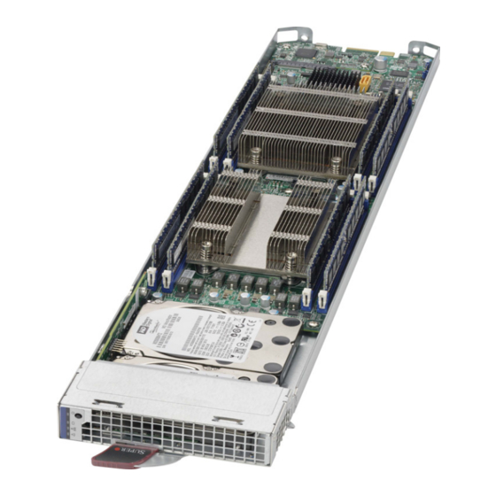
Chapter 4 MicroBlade Module Features Figure 4-1. MBI-6128R-T2/T2X Blade Unit Front View This chapter describes the MBI-6128R-T2/T2X MicroBlade module unit. Installation and maintenance should be performed by experienced technicians only. Figure 4-1 for a front view of the blade unit and Table 4-1 for its features. -
Page 44: Control Panel
MBI-6128R-T2/T2X MicroBlade Module User’s Manual Control Panel Each MicroBlade module has a similar control panel (Figure 4-2) with power on/off button, reset button and LEDs on the front left side of the module. The numbers mentioned in Figure 4-2 are described in Table 4-2. -
Page 45: Power Button
Chapter 4: MicroBlade Module Features Power Button Each MicroBlade module has its own power button so that individual blade units within the enclosure may be turned on or off independently of the others. Press the power button (#1) to turn on the blade server. The power LED (#3) will turn green. To turn off, press and hold the power button for >4 seconds and the power LED will turn orange. -
Page 46: Motherboard
MBI-6128R-T2/T2X MicroBlade Module User’s Manual Motherboard The motherboard of the MBI-6128R-T2/T2X MicroBlade module unit is a proprietary design, which is based on the Intel Xeon E5-2600 V3/V4 processor. See Figure 4-4 for a block diagram of this chipset, Figure 4-3... -
Page 47: Jumpers
Chapter 4: MicroBlade Module Features Figure 4-4. Intel B1DRi Block Diagram DDRIV DDRIV 1333/2133 1333/2133 1.65~1.82V working range DDRIV DDRIV VCCP0 12v VCCP1 12v 1333/2133 1333/2133 VR12.5 VR12.5 5 PHASE 5 PHASE 120W 120W 9.6G SNB CORE SNB CORE DDR-IV DDR-IV 9.6G DDRIV... -
Page 48: Blade Unit Components
SATA DOM LAN Board Memory Support The MBI-6128R-T2/T2X MicroBlade module supports up to 256 GB VLP RDIMM of DDR4 2400/2133 MHz speed, 32 GB, 16 GB, 8 GB and 4 GB size memory in eight (8) 288-pin RDIMM sockets. See... -
Page 49: Hard Disk Drives
RAID Setup. WARNING: Enterprise level hard disk drives are recommended for use in Supermicro chassis and servers. For information on recommended HDDs, visit the Supermicro Web site http://www.supermicro.com/products/nfo/storage.cfm. Blade Power Consumption Page Using the Web-based Management Utility from the CMM module you may use the... - Page 50 MBI-6128R-T2/T2X MicroBlade Module User’s Manual...
-
Page 51: Chapter 5 Bios
BIOS Introduction This chapter describes the BIOS for the MBI-6128R-T2/T2X MicroBlade module. This MicroBlade module uses a 128 MB SPI Flash EEPROM with AMI® BIOS™ that is stored in a flash chip. This BIOS can be easily upgraded using a floppy disk-based program. -
Page 52: Bios Updates
MBI-6128R-T2/T2X MicroBlade Module User’s Manual BIOS Updates It may be necessary to update the BIOS used in the blade modules on occasion. However, it is recommended that you not update BIOS if you are not experiencing problems with a blade module. -
Page 53: Running Setup
Chapter 5: BIOS Note: Replace filename.rom by the actual ROM file name (such as B8DTE142.rom for example) in the command. Running Setup Note: Default settings are in bold text unless otherwise noted. The BIOS setup options described in this section are selected by choosing the appropriate text from the M BIOS S screen. -
Page 54: Main Bios Setup
MBI-6128R-T2/T2X MicroBlade Module User’s Manual Main BIOS Setup Figure 5-1. BIOS Setup Screen All Main Setup options are described in this section. Use the U arrow keys to move among the different settings in each menu. Use the L arrow keys to IGHT change the options for each setting. -
Page 55: Advanced Setup
Chapter 5: BIOS Advanced Setup Choose Advanced from the BIOS Setup Utility main menu with the arrow keys to display the A menu. The items with a triangle beside them are DVANCED ETUP sub-menus that can be accessed by highlighting the item and pressing <E >. - Page 56 MBI-6128R-T2/T2X MicroBlade Module User’s Manual Table 5-3. Boot Feature Sub-menu Menu Option Description Use this feature to select the screen display between the POST messages and the OEM logo upon bootup. Select Disabled to display the POST Quiet Boot messages. Select Enabled to display the OEM logo instead of the normal POST messages.
- Page 57 Chapter 5: BIOS Table 5-4. CPU Configuration Sub-menu (Continued) Menu Option Description Use this setting to specify the number of cores to enable. Use the number Core’s Enabled pad “+” or “-” keys to specify a number up to 12. The number 0 means all cores with 12 cores available.
- Page 58 MBI-6128R-T2/T2X MicroBlade Module User’s Manual Table 5-5. Chipset Configuration Sub-menu Menu Option Description North Bridge This sub-menu configures North Bridge features and shows configuration Configuration information. IIO Configuration Use this sub-menu to set IIO configuration features and optons. Set this option to allow DFX Lock Bits to remain clear. Options include EV DFX Features Enable and Disable.
- Page 59 Chapter 5: BIOS Table 5-5. Chipset Configuration Sub-menu (Continued) Menu Option Description IOU0 (IIO PCIe This setting selects PCIe port bifurcation for selected slot(s). Options Port 2) include x4x4x4x4, x4x4x8, x8x4x4, x8x8, x16 and Auto. IOU1 (IIO PCIe This setting selects PCIe port bifurcation for selected slot(s). Options Port 3) include x4x4x4x4, x4x4x8, x8x4x4, x8x8, x16 and Auto.
- Page 60 MBI-6128R-T2/T2X MicroBlade Module User’s Manual Table 5-5. Chipset Configuration Sub-menu (Continued) Menu Option Description DRAM RAPL Use this setting to set the DRAM RAPL Baseline mode. Options include Baseline Disabled, DRAM RAPL Mode 0 and DRAM RAPL Mode 1. Use this setting to configure Thermal Throttling mode. Options include Set Throttling Mode Disabled and CLTT.
- Page 61 Chapter 5: BIOS Table 5-5. Chipset Configuration Sub-menu (Continued) Menu Option Description This setting enables or disables USB 3.0 (XHCI) controller support. USB3.0 Support Options include Smart Auto, Auto, Enabled or Disabled. This setting controls the USB EHCI (USB 2.0) functions. One EHCI EHCI1 controller must always be enabled.
- Page 62 MBI-6128R-T2/T2X MicroBlade Module User’s Manual Table 5-8. Server ME Configuration Sub-menu Menu Option Description General ME Configuration General ME configuration information is displayed at the top of this screen. Information The altitude of the platform location above sea level, expressed in meters, Altitude is set using the keyboard’s number pad “+”...
- Page 63 Chapter 5: BIOS Table 5-9. PCIe/PCI/PnP Configuration Sub-menu (Continued) Menu Option Description This setting allocates MMIOH size per CPU. Options include 256G, 128G, MMIO High Size 512G and 1024G. CPU1 Slot 1 PCI-E This setting enables or disables the PCIe Slot OPROM option.Options OPROM include Disabled, Legacy or EFI.
- Page 64 MBI-6128R-T2/T2X MicroBlade Module User’s Manual Table 5-11. Serial Port Console Redirection Sub-menu Menu Option Description COM1 Console Redirection, COM2/SOL/Legacy Console Redirection Sub-menus Select Enabled to enable console redirection support for a serial port Console Redirection specified by the user. The options are Enabled and Disabled.
- Page 65 Chapter 5: BIOS Table 5-11. Serial Port Console Redirection Sub-menu (Continued) Menu Option Description This feature selects the settings for Function Keys and KeyPad used for Putty KeyPad Putty, which is a terminal emulator designed for the Windows OS. The options are VT100, LINUX, XTERMR6, SC0, ESCN, and VT400.
- Page 66 MBI-6128R-T2/T2X MicroBlade Module User’s Manual Table 5-12. ACPI Settings Sub-menu Menu Option Description This feature Enables the Windows Hardware Error Architecture (WHEA) support WHEA Support for the Windows 2008 (or a later vision) operating system. The options are Enabled and Disabled.
-
Page 67: Event Logs Setup
Chapter 5: BIOS Event Logs Setup Table 5-15. Event Logs Menu Menu Option Description Change SMBIOS This sub-menu allows you to change the SMBIOS Event Log configuration Event Log Settings settings. Change this setting to enable or disable all features of the SMBIOS Event Logging during system boot. -
Page 68: Ipmi Setup
MBI-6128R-T2/T2X MicroBlade Module User’s Manual IPMI Setup Table 5-16. IPMI Menu Menu Option Description IPMI Information This item indicates the IPMI firmware revision used in your system. Use this sub-menu to configure the System Event Log. System Event Log NOTE: All values changed here in this sub-menu do not take effect until the computer is restarted. -
Page 69: Security
Chapter 5: BIOS Security Choose Security from the BIOS Setup main menu with the arrow keys to bring up the menu. Security setting options are displayed by highlighting the setting ECURITY ETUP using the arrow keys and pressing <E >. All Security BIOS settings are described in NTER Table 5-17 below. -
Page 70: 5-10 Save & Exit
MBI-6128R-T2/T2X MicroBlade Module User’s Manual 5-10 Save & Exit Choose S & E from the 128 MB SPI Flash EEPROM with AMI® BIOS BIOS Setup Utility main menu with the arrow keys to display the S & E menu. All Exit... -
Page 71: Appendix Aami Uefi Bios Post Codes
Appendix A AMI UEFI BIOS POST Codes A status code is a data value used to indicate progress during the boot phase. A subset of these status codes, known commonly as checkpoints, indicate common phases of the BIOS boot process. Checkpoints are typically output to I/O port 80h, but Aptio 4.x core can be configured to send status codes to a variety of sources. -
Page 72: Standard Checkpoints
MBI-6128R-T2/T2X MicroBlade Module User’s Manual Standard Checkpoints Table A-2. SEC Phase Codes Description Status Code 0x00 Not Used Progress Codes 0x01 Power on. Reset type detection (soft/hard). 0x02 AP initialization before microcode loading 0x03 North Bridge initialization before microcode loading... - Page 73 Appendix A: AMI UEFI BIOS POST Codes Table A-3. PEI Phase Status Codes Description 0x19 Pre-memory South Bridge initialization is started 0x1A Pre-memory South Bridge initialization (South Bridge module specific) 0x1B Pre-memory South Bridge initialization (South Bridge module specific) 0x1C Pre-memory South Bridge initialization (South Bridge module specific) 0x1D –...
- Page 74 MBI-6128R-T2/T2X MicroBlade Module User’s Manual Table A-3. PEI Phase Status Codes Description 0x53 Memory initialization error. No usable memory detected 0x54 Unspecified memory initialization error. 0x55 Memory not installed 0x56 Invalid CPU type or Speed 0x57 CPU mismatch 0x58 CPU self test failed or possible CPU cache error...
- Page 75 Appendix A: AMI UEFI BIOS POST Codes Table A-3. PEI Phase Status Codes Description 0xFA Invalid recovery capsule 0xFB – 0xFF Reserved for future AMI error codes Table A-4. PEI Beep Codes # of Beeps Description Memory not Installed Memory was installed twice (InstallPeiMemory routine in PEI Core called twice) Recovery started DXEIPL was not found...
- Page 76 MBI-6128R-T2/T2X MicroBlade Module User’s Manual Table A-5. DXE Phase Status Codes Description 0x70 South Bridge DXE initialization is started 0x71 South Bridge DXE SMM initialization is started 0x72 South Bridge devices initialization 0x73 South Bridge DXE Initialization (South Bridge module specific)
- Page 77 Appendix A: AMI UEFI BIOS POST Codes Table A-5. DXE Phase Status Codes Description 0xA5 SCSI Reset 0xA6 SCSI Detect 0xA7 SCSI Enable 0xA8 Setup Verifying Password 0xA9 Start of Setup 0xAA Reserved for ASL (see ASL Status Codes section below) 0xAB Setup Input Wait 0xAC...
- Page 78 MBI-6128R-T2/T2X MicroBlade Module User’s Manual Table A-5. DXE Phase Status Codes Description 0xDA Boot Option is failed (StartImage returned error) 0xDB Flash update is failed 0xDC Reset protocol is not available Table A-6. DXE Beep Codes # of Beeps Description...
-
Page 79: Oem-Reserved Checkpoint Ranges
Appendix A: AMI UEFI BIOS POST Codes OEM-Reserved Checkpoint Ranges Table A-8. OEM-Reserved Checkpoint Ranges Status Codes Description 0x05 OEM SEC initialization before microcode loading 0x0A OEM SEC initialization after microcode loading 0x1D – 0x2A OEM pre-memory initialization codes 0x3F – 0x4E OEM PEI post memory initialization codes 0x80 –... - Page 80 MBI-6128R-T2/T2X MicroBlade Module User’s Manual A-10...
- Page 81 Disclaimer The products sold by Supermicro are not intended for and will not be used in life support systems, medical equipment, nuclear facilities or systems, aircraft, aircraft devices, aircraft/emergency communication devices or other critical systems whose failure to perform be reasonably expected to result in significant injury or loss of life or catastrophic property damage.
Need help?
Do you have a question about the MBI-6128R-T2 and is the answer not in the manual?
Questions and answers