Table of Contents
Advertisement
Quick Links
Advertisement
Table of Contents

Related Manuals for Supermicro MBI-6418A-T5H


Summary of Contents for Supermicro MBI-6418A-T5H
- Page 1 MBI-6418A-T5H/T7H MicroBlade Module User’s Manual Revison 1.0b...
- Page 2 This product, including software and documentation, is the property of Supermicro and/or its licensors, and is supplied only under a license. Any use or reproduction of this product is not allowed, except as expressly permitted by the terms of said license.
- Page 3 MicroBlade module. Chapter 3: Setup and Installation Refer to this chapter for details on installing the MBI-6418A-T5H/T7H MicroBlade module into the MicroBlade chassis. Other sections cover the installation and placement of memory modules and the installation of hard disk drives into the blade module.
- Page 4 MBI-6418A-T5H/T7H MicroBlade Module User’s Manual Notes...
-
Page 5: Table Of Contents
1-2 Blade Module Features ..............1-2 Processors ....................1-2 Memory ....................1-2 Storage....................1-3 RAID ....................... 1-3 Density ....................1-3 1-3 Contacting Supermicro ..............1-4 Chapter 2 Standardized Warning Statements ..... 2-1 2-1 About Standardized Warning Statements ........2-1 Warning Definition................... 2-1 Installation Instructions ................ - Page 6 MBI-6418A-T5H/T7H MicroBlade Module User’s Manual Populating Memory Slots ................ 3-4 Memory Support ..................3-4 DIMM Installation ..................3-6 3-5 Hard Disk Drive Installation ............. 3-7 3-6 Installing the Operating System ............3-7 Installing with a SATA-DOM Module ............3-7 Installing via PXE Boot................3-8 Installing via Virtual Media (Drive Redirection) ........
- Page 7 Table of Contents Appendix A AMI UEFI BIOS POST Codes ......A-1 A-1 Checkpoint Ranges ................A-1 A-2 Standard Checkpoints ..............A-2 A-3 OEM-Reserved Checkpoint Ranges ..........A-9...
- Page 8 MBI-6418A-T5H/T7H MicroBlade Module User’s Manual Notes viii...
-
Page 9: Chapter 1 Introduction
• Product drivers and utilities: ftp://ftp.supermicro.com • Product safety information: http://super-dev/about/policies/safety_information.cfm • If you have any questions, please contact our support team at: support@supermicor.com Note: A complete list of safety warnings is provided on the Supermicro web site at http://www.supermicro.com/about/policies/safety_information.cfm. -
Page 10: Blade Module Features
Each node of the MBI-6418A-T5H/T7H MicroBlade module supports a single BGA1283 Intel ATOM C2750/C2550 series processors in a BGA1283 socket embedded in the motherboard. Refer to the Supermicro web site for a complete listing of supported processors (http:// www.supermicro.com/products/microblade). Please note that you will need to check the detailed specifications of a particular blade module for a list of the CPUs it supports. -
Page 11: Storage
Chapter 1: Introduction Storage Each node in the MBI-6418A-T5H/T7H MicroBlade module has one 2.5" SATA3 HDD/ SSD internally mounted and one SATA-DOM drive that it can also use for storage or for installation of the node’s operating system. See Chapter 3: " Setup and Installation" on page 3-1 for storage installation details. -
Page 12: Contacting Supermicro
MBI-6418A-T5H/T7H MicroBlade Module User’s Manual Contacting Supermicro Headquarters Address: Super Micro Computer, Inc. 980 Rock Ave. San Jose, CA 95131 U.S.A. Tel: +1 (408) 503-8000 Fax: +1 (408) 503-8008 marketing@supermicro.com (General Information) Email: support@supermicro.com (Technical Support) Web Site: www.supermicro.com Europe Address: Super Micro Computer B.V. -
Page 13: Chapter 2 Standardized Warning Statements
The following statements are industry standard warnings, provided to warn the user of situations which have the potential for bodily injury. Should you have questions or experience difficulty, contact Supermicro's Technical Support department for assistance. Only certified technicians should attempt to install or configure components. - Page 14 MBI-6418A-T5H/T7H MicroBlade Module User’s Manual Warnung WICHTIGE SICHERHEITSHINWEISE Dieses Warnsymbol bedeutet Gefahr. Sie befinden sich in einer Situation, die zu Verletzungen führen kann. Machen Sie sich vor der Arbeit mit Geräten mit den Gefahren elektrischer Schaltungen und den üblichen Verfahren zur Vorbeugung vor Unfällen vertraut.
-
Page 15: Installation Instructions
Chapter 2: Standardized Warning Statements 이 경고 기호는 위험이 있음을 알려 줍니다 . 작업자의 신체에 부상을 야기 할 수 있는 상태에 있게 됩니다 . 모든 장비에 대한 작업을 수행하기 전에 전기회로와 관련된 위험 요소들을 확인하시고 사전에 사고를 방지할 수 있도록 표준 작업절차를 준수해 주시기 바랍니다... -
Page 16: Circuit Breaker
MBI-6418A-T5H/T7H MicroBlade Module User’s Manual ﻣﺼﺪر ﻟﻠﻄﺎﻗﺔ اﻟﻨﻈﺎم إﻟﻰ ﻗﺒﻞ ﺗﻮﺻﯿﻞ ﺘﺮﻛﯿﺐ اﻗﺮ إرﺷﺎدات اﻟ 시스템을 전원에 연결하기 전에 설치 안내를 읽어주십시오 . Waarschuwing Raadpleeg de installatie-instructies voordat u het systeem op de voedingsbron aansluit. Circuit Breaker Warning! This product relies on the building's installation for short-circuit (overcurrent) protection. -
Page 17: Power Disconnection Warning
Chapter 2: Standardized Warning Statements ﻓﻲ اﻟﺘﻲ ﺗﻢ ﺗﺜﺒﯿﺘﮭﺎ ﻣﻦ اﻟﺪواﺋﺮاﻟﻘﺼﯿﺮة اﻟﺤﻤﺎﯾﺔ ﻣﻌﺪات ﯾﻌﺘﻤﺪ ﻋﻠﻰ ھﺬا اﻟﻤﻨﺘﺞ اﻟﻤﺒﻨﻰ أﻛﺜﺮ ﻣﻦ ﻟﯿﺲ ﻮﻗﺎﺋﻲ اﻟ اﻟﺠﮭﺎز ﺗﻘﯿﯿﻢ أن ﺗﺄﻛﺪ ﻣﻦ 20A, 250V 경고 ! 이 제품은 전원의 단락 ( 과전류 ) 방지에 대해서 전적으로 건물의 관련 설비에 의존합니 다... -
Page 18: Equipment Installation
MBI-6418A-T5H/T7H MicroBlade Module User’s Manual ¡Advertencia! El sistema debe ser disconnected de todas las fuentes de energía y del cable eléctrico quitado de los módulos de fuente de alimentación antes de tener acceso el interior del chasis para instalar o para quitar componentes de sistema. -
Page 19: Restricted Area
Chapter 2: Standardized Warning Statements Warnung Das Installieren, Ersetzen oder Bedienen dieser Ausrüstung sollte nur geschultem, qualifiziertem Personal gestattet werden. ¡Advertencia! Solamente el personal calificado debe instalar, reemplazar o utilizar este equipo. Attention Il est vivement recommandé de confier l'installation, le remplacement et la maintenance de ces équipements à... - Page 20 MBI-6418A-T5H/T7H MicroBlade Module User’s Manual Warnung Diese Einheit ist zur Installation in Bereichen mit beschränktem Zutritt vorgesehen. Der Zutritt zu derartigen Bereichen ist nur mit einem Spezialwerkzeug, Schloss und Schlüssel oder einer sonstigen Sicherheitsvorkehrung möglich. ¡Advertencia! Esta unidad ha sido diseñada para instalación en áreas de acceso restringido. Sólo puede obtenerse acceso a una de estas áreas mediante la utilización de una...
-
Page 21: Battery Handling
Chapter 2: Standardized Warning Statements Battery Handling Warning! There is the danger of explosion if the battery is replaced incorrectly. Replace the battery only with the same or equivalent type recommended by the manufacturer. Dispose of used batteries according to the manufacturer's instructions. 電池の取り扱い... -
Page 22: Redundant Power Supplies
MBI-6418A-T5H/T7H MicroBlade Module User’s Manual 배터리가 올바르게 교체되지 않으면 폭발의 위험이 있습니다 . 기존 배터리와 동일하거 나 제조사에서 권장하는 동등한 종류의 배터리로만 교체해야 합니다 . 제조사의 안내에 따라 사용된 배터리를 처리하여 주십시오 . Waarschuwing Er is ontploffingsgevaar indien de batterij verkeerd vervangen wordt. Vervang de batterij slechts met hetzelfde of een equivalent type die door de fabrikant aanbevolen wordt. -
Page 23: Backplane Voltage
Chapter 2: Standardized Warning Statements اﻣﺪاد اﻟﻄﺎﻗﺔ ﺑﻮﺣﺪات ﻋﺪة اﺗﺼﺎﻻت ﺠﮭﺎز اﻟ ﯾﻜﻮن ﻟﮭﺬا ﻗﺪ اﻟﻜﮭﺮﺑﺎء ﻋﻦ ﻮﺣﺪة اﻟ ﻟﻌﺰل ﻛﺎﻓﺔ اﻻﺗﺼﺎﻻت ﯾﺠﺐ إزاﻟﺔ 경고 ! 이 장치에는 한 개 이상의 전원 공급 단자가 연결되어 있을 수 있습니다 . 이 장치에 전 원을... -
Page 24: Comply With Local And National Electrical Codes
MBI-6418A-T5H/T7H MicroBlade Module User’s Manual اﻟﻠﻮﺣﺔ أواﻟﻄﺎﻗﺔ اﻟﻤﻮﺟﻮدة ﻋﻠﻰ اﻟﺘﯿﺎر اﻟﻜﮭﺮﺑﺎﺋﻲ ﻣﻦ ﺧﻄﺮ ھﻨﺎك ھﺬا اﻟﺠﮭﺎز ﺧﺪﻣﺔ ﻛﻦ ﺣﺬرا ﻋﻨﺪ ﯾﻌﻤﻞ اﻟﻨﻈﺎم ﻋﻨﺪﻣﺎ ﯾﻜﻮن 경고 ! 시스템이 동작 중일 때 후면판 (Backplane) 에는 위험한 전압이나 에너지가 발생 합니 다 . 서비스 작업 시 주의하십시오 . -
Page 25: Product Disposal
Chapter 2: Standardized Warning Statements 경고 ! 현 지역 및 국가의 전기 규정에 따라 장비를 설치해야 합니다 . Waarschuwing Bij installatie van de apparatuur moet worden voldaan aan de lokale en nationale elektriciteitsvoorschriften. Product Disposal Warning! Ultimate disposal of this product should be handled according to all national laws and regulations. -
Page 26: Hot Swap Fan Warning
MBI-6418A-T5H/T7H MicroBlade Module User’s Manual 경고 ! 이 제품은 해당 국가의 관련 법규 및 규정에 따라 폐기되어야 합니다 . Waarschuwing De uiteindelijke verwijdering van dit product dient te geschieden in overeenstemming met alle nationale wetten en reglementen. Hot Swap Fan Warning... -
Page 27: Power Cable And Ac Adapter
Electrical Appliance and Material Safety Law prohibits the use of UL or CSA -certified cables (that have UL/CSA shown on the code) for any other electrical devices than products designated by Supermicro only. 電源コードと AC アダプター... - Page 28 Fehlfunktion oder ein Brand entstehen. Elektrische Geräte und Material Safety Law verbietet die Verwendung von UL-oder CSA-zertifizierte Kabel, UL oder CSA auf der Code für alle anderen elektrischen Geräte als Produkte von Supermicro nur bezeichnet gezeigt haben.
- Page 29 Het gebruik van andere kabels en adapters kan leiden tot een storing of een brand. Elektrisch apparaat en veiligheidsinformatiebladen wet verbiedt het gebruik van UL of CSA gecertificeerde kabels die UL of CSA die op de code voor andere elektrische apparaten dan de producten die door Supermicro alleen. 2-17...
- Page 30 MBI-6418A-T5H/T7H MicroBlade Module User’s Manual Notes 2-18...
-
Page 31: Chapter 3 Setup And Installation
This chapter covers the setup and installation of the MicroBlade module and its components. Installing MicroBlade Modules Up to twenty-eight MBI-6418A-T5H/T7H MicroBlade module may be installed into a single MBE-628L-416/816 MicroBlade module enclosure. MicroBlade modules with Windows and Linux operating systems may be mixed together in the same blade enclosure. -
Page 32: Removing A Microblade Module Unit From The Enclosure
MBI-6418A-T5H/T7H MicroBlade Module User’s Manual Removing a MicroBlade Module Unit from the Enclosure Although the MicroBlade module system may continue to run, individual MicroBlade modules should always be powered down before removing them from the enclosure. Removing a MicroBlade Module Unit from the Enclosure 1. -
Page 33: Onboard Battery Installation
Chapter 3: Setup and Installation Figure 3-1. Inserting a MicroBlade Module into the Enclosure Onboard Battery Installation A battery is included on the serverboard to supply certain volatile memory components with power when power has been removed from the MicroBlade module. If this battery dies, it must be replaced with an equivalent CR2032 Lithium 3V battery. -
Page 34: Memory Installation
You should not mix DIMMs of different sizes and speeds. Note: Check the Supermicro website for a list of memory modules that have been validated with the B1SA4-2750F/B1SA4-2550F motherboard. Note: Though multiple DIMM memory module types and speeds may be supported, you need to use DIMM memory modules of the same speed and type. - Page 35 Chapter 3: Setup and Installation Figure 3-3. SO DIMM Sideways View P1-DIMMA1 P2-DIMMA1 P3-DIMMA1 P4-DIMMA1 P1-DIMMB1 P2-DIMMB1 P3-DIMMB1 P4-DIMMB1 Table 3-1. Memory Population Guidelines P1/P2/P3/P4-DIMMA1 P1/P2/P3/P4-DIMMB1 Total System Memory 16GB 16GB 16GB 16GB 16GB 32GB...
-
Page 36: Dimm Installation
MBI-6418A-T5H/T7H MicroBlade Module User’s Manual DIMM Installation Caution: Exercise extreme care when installing or removing SODIMM modules to prevent any possible damage. Installing/Removing SODIMM Memory Modules 1. Power down the MicroBlade module (see "Powering Down a MicroBlade Module Unit" on page 3-1). -
Page 37: Hard Disk Drive Installation
An operating system (OS) must be installed on each MicroBlade module. Blades with Microsoft Windows OS and blades with Linux OS can both occupy and operate within the same blade enclosure. Refer to the SuperMicro web site for a complete list of supported operating systems. -
Page 38: Installing Via Pxe Boot
MBI-6418A-T5H/T7H MicroBlade Module User’s Manual Installing via PXE Boot PXE (Preboot Execution Environment) is used to boot a computer over a network. To install the OS via PXE, the following conditions must be met: 1. The PXE B option in BIOS must be enabled. -
Page 39: Chapter 4 Microblade Module Features
Chapter 4 MicroBlade module Features Figure 4-1. MBI-6418A-T5H/T7H Blade Unit Front View This chapter describes the MBI-6418A-T5H/T7H MicroBlade module unit. Installation and maintenance should be performed by experienced technicians only. Figure 4-1 for a front view of the blade unit and Table 4-1 for its features. -
Page 40: Control Panel
MBI-6418A-T5H/T7H MicroBlade Module User’s Manual Control Panel Each MicroBlade module has a similar control panel (Figure 4-2) with power on/off button, reset button and LEDs on the front left side of the module. The numbers mentioned in Figure 4-2 are described in Table 4-2. -
Page 41: Power Button
Chapter 4: MicroBlade module Features Power Button Each MicroBlade module has its own power button so that individual blade units within the enclosure may be turned on or off independently of the others. Press the power button (#1) to turn on the blade server. The power LED (#3) will turn green. To turn off, press and hold the power button for >4 seconds and the power LED will turn orange. -
Page 42: Serverboard
MBI-6418A-T5H/T7H MicroBlade Module User’s Manual Serverboard The serverboard of the MBI-6418A-T5H/T7H MicroBlade module unit is a proprietary design, which is based on the Intel Intel ATOM C2750/C2550 processor. See Figure 4-4 for a block diagram of this chipset, Figure 4-3... - Page 43 Chapter 4: MicroBlade module Features Figure 4-3. B1SA4-2750F Serverboad Table 4-4. B1SA4-2750F Mainboard Layout Item Description One Intel ATOM C2750/C2550 processor embedded in a BGA1283 socket for each node (4 total) One SATA3 SATA-DOM connector for each node (4 total)
-
Page 44: Jumpers
MBI-6418A-T5H/T7H MicroBlade Module User’s Manual Table 4-4. B1SA4-2750F Mainboard Layout (Continued) Item Description Two SODIMM slots for each node (8 total) for SODIMM memory modules One 2.5" SATA3 HDD/SSD for each node (two not shown, 4 total) Onboard Battery CMOS Clear Figure 4-4. - Page 45 Chapter 4: MicroBlade module Features Clearing CMOS 1. First power down the blade and remove it from the enclosure. 2. Remove the blade cover to access the mainboard (see "Removing/Replacing the Blade Cover" on page 3-2 for further details). Short the CMOS pads with a metal object such as a small screwdriver.
-
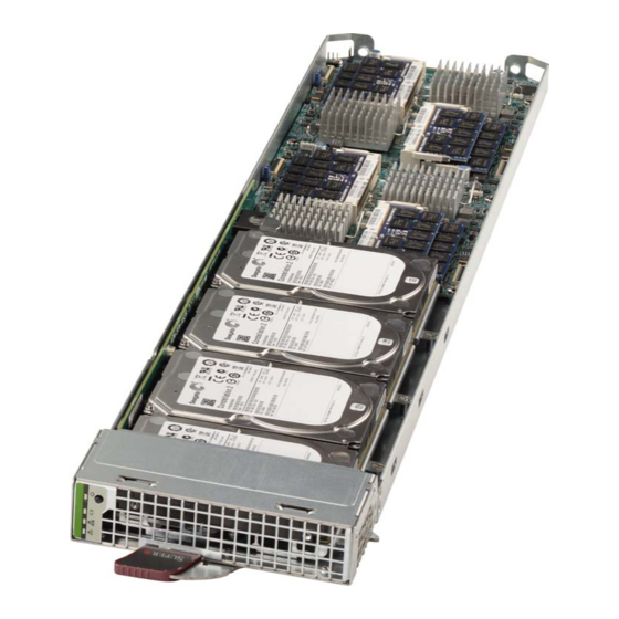
Page 46: Blade Unit Components
CPU/Heatsinks (4) Hard Drive Backplane Memory Support The MBI-6418A-T5H/T7H MicroBlade module supports up to 32 GB of DDR3 1600/ 1333 MHz speed, 16GB, 8GB, 4GB, 2GB and 1GB size SODIMM memory in two (2) 204-pin SODIMM sockets. See Section 3-4: Memory Installation on page 3-4 for further details on serverboard memory installation. -
Page 47: Hard Disk Drives
SSD drives. The drives cannot be removed or replaced without powering down the blade unit they reside in. See Chapter 1 for information on RAID Setup. WARNING: Enterprise level hard disk drives are recommended for use in Supermicro chassis and servers. For information on recommended HDDs, visit the Supermicro Web site http://www.supermicro.com/products/nfo/storage.cfm... - Page 48 MBI-6418A-T5H/T7H MicroBlade Module User’s Manual 4-10...
-
Page 49: Chapter 5 Bios
BIOS Introduction This chapter describes the BIOS for the MBI-6418A-T5H/T7H MicroBlade module. This MicroBlade module uses a 32 MB SPI Flash EEPROM with AMI® BIOS™ that is stored in a flash chip. This BIOS can be easily upgraded using a floppy disk-based program. -
Page 50: Bios Updates
MBI-6418A-T5H/T7H MicroBlade Module User’s Manual BIOS Updates It may be necessary to update the BIOS used in the blade modules on occasion. However, it is recommended that you not update BIOS if you are not experiencing problems with a blade module. -
Page 51: Running Setup
Chapter 5: BIOS Note: Replace filename.rom by the actual ROM file name (such as B8DTE142.rom for example) in the command. Running Setup Note: Default settings are in bold text unless otherwise noted. The BIOS setup options described in this section are selected by choosing the appropriate text from the M BIOS S screen. -
Page 52: Main Bios Setup
MBI-6418A-T5H/T7H MicroBlade Module User’s Manual Main BIOS Setup Figure 5-1. BIOS Setup Screen All Main Setup options are described in this section. Use the U arrow keys to move among the different settings in each menu. Use the L arrow keys to IGHT change the options for each setting. -
Page 53: Advanced Setup
Chapter 5: BIOS Advanced Setup Choose Advanced from the BIOS Setup Utility main menu with the arrow keys to display the A menu. The items with a triangle beside them are DVANCED ETUP sub-menus that can be accessed by highlighting the item and pressing <E >. - Page 54 MBI-6418A-T5H/T7H MicroBlade Module User’s Manual Table 5-3. Boot Feature Submenu (Continued) Menu Option Description Interrupt 19 is the software interrupt that handles the boot disk function. When this item is set to Enabled, the ROM BIOS of the host adaptors will "capture"...
- Page 55 Chapter 5: BIOS Table 5-4. CPU Configuration Submenu (Continued) Menu Option Description This setting is only available when supported by the CPU. Use this feature to TM2 Mode select the throttling mode for TM2. The options are LEM Throttling and Adaptive Throttling.
- Page 56 MBI-6418A-T5H/T7H MicroBlade Module User’s Manual Table 5-4. CPU Configuration Submenu (Continued) Menu Option Description If this feature is set to Enabled, the default setting will be set to "Uncacheable" in MTRR Default As the Memory-Type-Range Table to protect the data stored in the MTRR table from Unccacheable being cached.
- Page 57 Chapter 5: BIOS Table 5-5. Chipset Configuration Sub-menu Menu Option Description North Bridge This sub-menu configures North Bridge features and shows configuration Configuration information. Memory Memory information for MRC Version, Total Memory and Memory Frequency is Information static displayed at the top of the screen. Pass Gate This sub-menu provides pass gate feature configuration settings.
- Page 58 MBI-6418A-T5H/T7H MicroBlade Module User’s Manual Table 5-5. Chipset Configuration Sub-menu (Continued) Menu Option Description Static displayed information for Pass Gate Max Failures, Pass Gate Max Pass Gate Repetition and Pass Gate Min Repetition is displayed at the bottom of the Information screen.
- Page 59 Chapter 5: BIOS Table 5-5. Chipset Configuration Sub-menu (Continued) Menu Option Description Demand Scrubbing is a process that allows the CPU to correct correctable memory errors found on a memory module. When the CPU or I/O issues a demand-read command, and the read data from memory turns out to be a Demand Scrub correctable error, the error will be corrected and sent to the requestor (the Enable...
- Page 60 MBI-6418A-T5H/T7H MicroBlade Module User’s Manual Table 5-5. Chipset Configuration Sub-menu (Continued) Menu Option Description This sets power mode Opcode for PCX. Pressing the “-” key on your keyboard PMOP Value for decreases the count by 1 while pressing the “+” key increases it by 1. Default is “7”, which is the maximum number for this field.
- Page 61 Chapter 5: BIOS Table 5-5. Chipset Configuration Sub-menu (Continued) Menu Option Description USB3.0 This setting enables or disables USB 3.0 (XHCI) controller support. Options Support include Enabled or Disabled. This item is a work-around solution for operating systems that do not support XHCI (Extensible Host Controller Interface) hand-off.
- Page 62 MBI-6418A-T5H/T7H MicroBlade Module User’s Manual Table 5-6. SATA Configuration Sub-menu (Continued) Menu Option Description ALPM (Aggressive Link Select Enabled to support Aggressive Link Power Management to enhance Power system power performance. The options are Disabled, and Enabled. Management) Overwrite SIR Values Select Enabled to overwrite SIR values. The options are Enabled, and Disabled.
- Page 63 Chapter 5: BIOS Table 5-7. PCIe/PCI/PnP Configuration Sub-menu (Continued) Menu Option Description This feature allows the user to set the Active State Power Management (ASPM) level for a PCI-E device. Select Force L0 to force all PCI-E links to operate at L0 state.
- Page 64 MBI-6418A-T5H/T7H MicroBlade Module User’s Manual Table 5-8. ACPI Settings Sub-menu Menu Option Description Select Enabled to activate the High Performance Event Timer (HPET) that produces periodic interrupts at a much higher frequency than a Real-time Clock (RTC) does in synchronizing multimedia streams, providing smooth playback...
- Page 65 Chapter 5: BIOS Table 5-9. SuperIO Device Configuration Sub-menu (Continued) Menu Option Description Use this setting to select an optimal setting for the Super IO device to use for the Change Settings Serial Port. Options include Auto, IO=3F8h/IRQ=4, IO=3F8h/IRQ=3~12, IO=2F8h/IRQ=3~12, IO=3E8h/IRQ=3~12 and IO=2E8h/IRQ=3~12 This setting allows you to set the Serial Port Mode to either Normal or High Serial Port Mode Speed.
- Page 66 MBI-6418A-T5H/T7H MicroBlade Module User’s Manual Table 5-10. Serial Port Console Redirection Sub-menu (Continued) Menu Option Description Select Enabled to capture the data displayed on a terminal and send it as text Recorder Mode messages to a remote server. The options are Disabled and Enabled.
- Page 67 Chapter 5: BIOS Table 5-10. Serial Port Console Redirection Sub-menu (Continued) Menu Option Description This feature allows the user to set the flow control for Console Redirection to prevent data loss caused by buffer overflow. Send a "Stop" signal to stop Flow Control sending data when the receiving buffer is full.
-
Page 68: Ipmi Setup
MBI-6418A-T5H/T7H MicroBlade Module User’s Manual IPMI Setup Table 5-11. IPMI Menu Menu Option Description IPMI Information This item indicates the IPMI firmware revision used in your system. Status BMC (Baseboard This item indicates the status of the IPMI firmware installed in your system. - Page 69 Chapter 5: BIOS Table 5-12. Event Logs Menu (Continued) Menu Option Description Select Erase Immediately for all messages to be automatically erased from the When Log is Full event log when the event log memory is full. The options are Do Nothing and Erase Immediately.
-
Page 70: Boot
MBI-6418A-T5H/T7H MicroBlade Module User’s Manual Boot Choose Boot from the 32 MB SPI Flash EEPROM with AMI® BIOS BIOS Setup Utility main menu with the arrow keys to bring up the B menu. Security setting ETUP options are displayed by highlighting the setting using the arrow keys and pressing <E... - Page 71 Chapter 5: BIOS Table 5-14. Security Menu Options (Continued) Menu Option Description Default Key Select Enabled to install the default Secure-Boot keys set by the manufacturer. Provision The options are Disabled and Enabled. Delete All Selecting this option forces the system to Setup mode and clear all secure boot Secure Boot variables (PK, KEK, db, Dbx and dbt).
- Page 72 MBI-6418A-T5H/T7H MicroBlade Module User’s Manual Table 5-14. Security Menu Options (Continued) Menu Option Description Append Select Yes to add the KEK from the manufacturer's defaults list to the existing KEK. Select No to load the KEK from a file. The options are Yes and No.
-
Page 73: 5-10 Save & Exit
Chapter 5: BIOS 5-10 Save & Exit Choose S & E from the 32 MB SPI Flash EEPROM with AMI® BIOS BIOS Setup Utility main menu with the arrow keys to display the S & E menu. All Exit ETUP BIOS settings are described in Table 5-15 below. - Page 74 MBI-6418A-T5H/T7H MicroBlade Module User’s Manual Notes 5-26...
-
Page 75: Appendix Aami Uefi Bios Post Codes
Appendix A AMI UEFI BIOS POST Codes A status code is a data value used to indicate progress during the boot phase. A subset of these status codes, known commonly as checkpoints, indicate common phases of the BIOS boot process. Checkpoints are typically output to I/O port 80h, but Aptio 4.x core can be configured to send status codes to a variety of sources. -
Page 76: Standard Checkpoints
MBI-6418A-T5H/T7H MicroBlade Module User’s Manual Standard Checkpoints Table A-2. SEC Phase Codes Description Status Code 0x00 Not Used Progress Codes 0x01 Power on. Reset type detection (soft/hard). 0x02 AP initialization before microcode loading 0x03 North Bridge initialization before microcode loading... - Page 77 Appendix A: AMI UEFI BIOS POST Codes Table A-3. PEI Phase Status Codes Description 0x19 Pre-memory South Bridge initialization is started 0x1A Pre-memory South Bridge initialization (South Bridge module specific) 0x1B Pre-memory South Bridge initialization (South Bridge module specific) 0x1C Pre-memory South Bridge initialization (South Bridge module specific) 0x1D –...
- Page 78 MBI-6418A-T5H/T7H MicroBlade Module User’s Manual Table A-3. PEI Phase Status Codes Description 0x53 Memory initialization error. No usable memory detected 0x54 Unspecified memory initialization error. 0x55 Memory not installed 0x56 Invalid CPU type or Speed 0x57 CPU mismatch 0x58 CPU self test failed or possible CPU cache error...
- Page 79 Appendix A: AMI UEFI BIOS POST Codes Table A-3. PEI Phase Status Codes Description 0xFA Invalid recovery capsule 0xFB – 0xFF Reserved for future AMI error codes Table A-4. PEI Beep Codes # of Beeps Description Memory not Installed Memory was installed twice (InstallPeiMemory routine in PEI Core called twice) Recovery started DXEIPL was not found...
- Page 80 MBI-6418A-T5H/T7H MicroBlade Module User’s Manual Table A-5. DXE Phase Status Codes Description 0x70 South Bridge DXE initialization is started 0x71 South Bridge DXE SMM initialization is started 0x72 South Bridge devices initialization 0x73 South Bridge DXE Initialization (South Bridge module specific)
- Page 81 Appendix A: AMI UEFI BIOS POST Codes Table A-5. DXE Phase Status Codes Description 0xA5 SCSI Reset 0xA6 SCSI Detect 0xA7 SCSI Enable 0xA8 Setup Verifying Password 0xA9 Start of Setup 0xAA Reserved for ASL (see ASL Status Codes section below) 0xAB Setup Input Wait 0xAC...
- Page 82 MBI-6418A-T5H/T7H MicroBlade Module User’s Manual Table A-5. DXE Phase Status Codes Description 0xDA Boot Option is failed (StartImage returned error) 0xDB Flash update is failed 0xDC Reset protocol is not available Table A-6. DXE Beep Codes # of Beeps Description...
-
Page 83: Oem-Reserved Checkpoint Ranges
Appendix A: AMI UEFI BIOS POST Codes OEM-Reserved Checkpoint Ranges Table A-8. OEM-Reserved Checkpoint Ranges Status Codes Description 0x05 OEM SEC initialization before microcode loading 0x0A OEM SEC initialization after microcode loading 0x1D – 0x2A OEM pre-memory initialization codes 0x3F – 0x4E OEM PEI post memory initialization codes 0x80 –... - Page 84 MBI-6418A-T5H/T7H MicroBlade Module User’s Manual Notes A-10...
- Page 85 Disclaimer The products sold by Supermicro are not intended for and will not be used in life support systems, medical equipment, nuclear facilities or systems, aircraft, aircraft devices, aircraft/emergency communication devices or other critical systems whose failure to perform be reasonably expected to result in significant injury or loss of life or catastrophic property damage.
- Page 86 MBI-6418A-T5H/T7H MicroBlade Module User’s Manual MBI-6418A-T5H/T7H...
Need help?
Do you have a question about the MBI-6418A-T5H and is the answer not in the manual?
Questions and answers