Table of Contents
Advertisement
Quick Links
Advertisement
Table of Contents

Related Manuals for Supermicro MicroBlade MBI-6219G-T8HX


Summary of Contents for Supermicro MicroBlade MBI-6219G-T8HX
- Page 1 MBI-6219G-T8HX MBI-6119G-T8HX MicroBlade™ Module User’s Manual Revison 1.0a...
- Page 2 This product, including software and documentation, is the property of Supermicro and/or its licensors, and is supplied only under a license. Any use or reproduction of this product is not allowed, except as expressly permitted by the terms of said license.
- Page 3 This manual is written for professional system integrators, Information Technology professionals, service personnel and technicians. It provides information for the installation and use of both the Supermicro MBI-6219G-T8HX and MBI-6119G-T8HXMicroBlade modules. Installation and maintenance should be performed by experienced professionals only.
- Page 4 MBI-6219G-T8HX /MBI-6119G-T8HX Blade Server Module User’s Manual Notes...
-
Page 5: Table Of Contents
Blade Enclosures ..................1-3 Processors ....................1-3 Memory ....................1-3 Storage ....................1-4 RAID ....................... 1-4 Density ....................1-4 1-3 Contacting Supermicro ..............1-5 Chapter 2 Standardized Warning Statements ..... 2-1 2-1 About Standardized Warning Statements ........2-1 Warning Definition................... 2-1 Installation Instructions ................ - Page 6 MBI-6219G-T8HX /MBI-6119G-T8HX Blade Server Module User’s Manual 3-4 Memory Installation ................3-4 Populating Memory Slots ................ 3-4 Memory Support ..................3-4 DIMM Installation ..................3-5 3-5 Hard Disk Drive Installation ............. 3-7 3-6 Installing the Operating System ............3-7 Installing with a SATA-DOM Module ............3-7 Installing via PXE Boot................
- Page 7 Appendix A AMI UEFI BIOS POST Codes ......A-1 A-1 Checkpoint Ranges ................A-1 A-2 Standard Checkpoints ..............A-2 A-3 OEM-Reserved Checkpoint Ranges ..........A-9...
- Page 8 MBI-6219G-T8HX /MBI-6119G-T8HX Blade Server Module User’s Manual Notes viii...
-
Page 9: Chapter 1 Introduction
Product drivers and utilities: ftp://ftp.supermicro.com • Product safety information: http://www.supermicro.com/about/policies/ safety_information.cfm • If you have any questions, please contact our support team at: support@supermicro.com Note: A complete list of safety warnings is provided on the Supermicro web site at http://www.supermicro.com/about/policies/safety_information.cfm. -
Page 10: Blade Module Features
MBI-6219G-T8HX/MBI-6119G-T8HX MicroBlade Module User’s Manual Blade Module Features Table 1-1 lists the main features of the MBI-6219G-T8HX/MBI-6119G-T8HX MicroBlade module. See the proceeding section for components typically included in a blade system and other optional components. Specific details for the MBI-6219G-T8HX/ MBI-6119G-T8HX MicroBlade module are found in Chapter 4: "MicroBlade Module Features"... -
Page 11: Blade Enclosures
FCBGA1440 socket. The MBI-6219G-T8HX supports two processors while the MBI-6119G-T8HX supports only one processor Refer to the Supermicro web site for a complete listing of supported processors (http:// www.supermicro.com/products/microblade). Please note that you will need to check the detailed specifications of a particular blade module for a list of the CPUs it supports. -
Page 12: Storage
MBI-6219G-T8HX/MBI-6119G-T8HX MicroBlade Module User’s Manual Storage The MBI-6219G-T8HX/MBI-6119G-T8HX MicroBlade module has one (1) 2.5" SATA3 HDD/SSD for an internally mounted drive per node. Additionally, two (2) M.2 and one (1) SATA-DOM connectors are available that can be used for connection to drives for storage or for installation of the node’s operating system for each node. -
Page 13: Contacting Supermicro
Address: Super Micro Computer, Inc. 980 Rock Ave. San Jose, CA 95131 U.S.A. Tel: +1 (408) 503-8000 Fax: +1 (408) 503-8008 marketing@supermicro.com (General Information) Email: support@supermicro.com (Technical Support) Web Site: www.supermicro.com Europe Address: Super Micro Computer B.V. Het Sterrenbeeld 28, 5215 ML ‘s-Hertogenbosch, The Netherlands... - Page 14 MBI-6219G-T8HX/MBI-6119G-T8HX MicroBlade Module User’s Manual...
-
Page 15: Chapter 2 Standardized Warning Statements
The following statements are industry standard warnings, provided to warn the user of situations which have the potential for bodily injury. Should you have questions or experience difficulty, contact Supermicro's Technical Support department for assistance. Only certified technicians should attempt to install or configure components. - Page 16 MBI-6219G-T8HX/MBI-6119G-T8HX MicroBlade Module User’s Manual Warnung WICHTIGE SICHERHEITSHINWEISE Dieses Warnsymbol bedeutet Gefahr. Sie befinden sich in einer Situation, die zu Verletzungen führen kann. Machen Sie sich vor der Arbeit mit Geräten mit den Gefahren elektrischer Schaltungen und den üblichen Verfahren zur Vorbeugung vor Unfällen vertraut.
-
Page 17: Installation Instructions
Chapter 2: Standardized Warning Statements 이 경고 기호는 위험이 있음을 알려 줍니다 . 작업자의 신체에 부상을 야기 할 수 있는 상태에 있게 됩니다 . 모든 장비에 대한 작업을 수행하기 전에 전기회로와 관련된 위험 요소들을 확인하시고 사전에 사고를 방지할 수 있도록 표준 작업절차를 준수해 주시기 바랍니다... -
Page 18: Circuit Breaker
MBI-6219G-T8HX/MBI-6119G-T8HX MicroBlade Module User’s Manual ﻣﺼﺪر ﻟﻠﻄﺎﻗﺔ اﻟﻨﻈﺎم إﻟﻰ ﻗﺒﻞ ﺗﻮﺻﯿﻞ ﺘﺮﻛﯿﺐ اﻗﺮ إرﺷﺎدات اﻟ 시스템을 전원에 연결하기 전에 설치 안내를 읽어주십시오 . Waarschuwing Raadpleeg de installatie-instructies voordat u het systeem op de voedingsbron aansluit. Circuit Breaker Warning! This product relies on the building's installation for short-circuit (overcurrent) protection. -
Page 19: Power Disconnection Warning
Chapter 2: Standardized Warning Statements ﻓﻲ اﻟﺘﻲ ﺗﻢ ﺗﺜﺒﯿﺘﮭﺎ ﻣﻦ اﻟﺪواﺋﺮاﻟﻘﺼﯿﺮة اﻟﺤﻤﺎﯾﺔ ﻣﻌﺪات ﯾﻌﺘﻤﺪ ﻋﻠﻰ ھﺬا اﻟﻤﻨﺘﺞ اﻟﻤﺒﻨﻰ أﻛﺜﺮ ﻣﻦ ﻟﯿﺲ ﻮﻗﺎﺋﻲ اﻟ اﻟﺠﮭﺎز ﺗﻘﯿﯿﻢ أن ﺗﺄﻛﺪ ﻣﻦ 20A, 250V 경고 ! 이 제품은 전원의 단락 ( 과전류 ) 방지에 대해서 전적으로 건물의 관련 설비에 의존합니 다... -
Page 20: Equipment Installation
MBI-6219G-T8HX/MBI-6119G-T8HX MicroBlade Module User’s Manual ¡Advertencia! El sistema debe ser disconnected de todas las fuentes de energía y del cable eléctrico quitado de los módulos de fuente de alimentación antes de tener acceso el interior del chasis para instalar o para quitar componentes de sistema. Attention Le système doit être débranché... -
Page 21: Restricted Area
Chapter 2: Standardized Warning Statements Warnung Das Installieren, Ersetzen oder Bedienen dieser Ausrüstung sollte nur geschultem, qualifiziertem Personal gestattet werden. ¡Advertencia! Solamente el personal calificado debe instalar, reemplazar o utilizar este equipo. Attention Il est vivement recommandé de confier l'installation, le remplacement et la maintenance de ces équipements à... - Page 22 MBI-6219G-T8HX/MBI-6119G-T8HX MicroBlade Module User’s Manual Warnung Diese Einheit ist zur Installation in Bereichen mit beschränktem Zutritt vorgesehen. Der Zutritt zu derartigen Bereichen ist nur mit einem Spezialwerkzeug, Schloss und Schlüssel oder einer sonstigen Sicherheitsvorkehrung möglich. ¡Advertencia! Esta unidad ha sido diseñada para instalación en áreas de acceso restringido. Sólo puede obtenerse acceso a una de estas áreas mediante la utilización de una herramienta especial, cerradura con llave u otro medio de seguridad.
-
Page 23: Battery Handling
Chapter 2: Standardized Warning Statements Battery Handling Warning! There is the danger of explosion if the battery is replaced incorrectly. Replace the battery only with the same or equivalent type recommended by the manufacturer. Dispose of used batteries according to the manufacturer's instructions. 電池の取り扱い... -
Page 24: Redundant Power Supplies
MBI-6219G-T8HX/MBI-6119G-T8HX MicroBlade Module User’s Manual 배터리가 올바르게 교체되지 않으면 폭발의 위험이 있습니다 . 기존 배터리와 동일하거 나 제조사에서 권장하는 동등한 종류의 배터리로만 교체해야 합니다 . 제조사의 안내에 따라 사용된 배터리를 처리하여 주십시오 . Waarschuwing Er is ontploffingsgevaar indien de batterij verkeerd vervangen wordt. Vervang de batterij slechts met hetzelfde of een equivalent type die door de fabrikant aanbevolen wordt. -
Page 25: Backplane Voltage
Chapter 2: Standardized Warning Statements اﻣﺪاد اﻟﻄﺎﻗﺔ ﺑﻮﺣﺪات ﻋﺪة اﺗﺼﺎﻻت ﺠﮭﺎز اﻟ ﯾﻜﻮن ﻟﮭﺬا ﻗﺪ اﻟﻜﮭﺮﺑﺎء ﻋﻦ ﻮﺣﺪة اﻟ ﻟﻌﺰل ﻛﺎﻓﺔ اﻻﺗﺼﺎﻻت ﯾﺠﺐ إزاﻟﺔ 경고 ! 이 장치에는 한 개 이상의 전원 공급 단자가 연결되어 있을 수 있습니다 . 이 장치에 전 원을... -
Page 26: Comply With Local And National Electrical Codes
MBI-6219G-T8HX/MBI-6119G-T8HX MicroBlade Module User’s Manual اﻟﻠﻮﺣﺔ أواﻟﻄﺎﻗﺔ اﻟﻤﻮﺟﻮدة ﻋﻠﻰ اﻟﺘﯿﺎر اﻟﻜﮭﺮﺑﺎﺋﻲ ﻣﻦ ﺧﻄﺮ ھﻨﺎك ھﺬا اﻟﺠﮭﺎز ﺧﺪﻣﺔ ﻛﻦ ﺣﺬرا ﻋﻨﺪ ﯾﻌﻤﻞ اﻟﻨﻈﺎم ﻋﻨﺪﻣﺎ ﯾﻜﻮن 경고 ! 시스템이 동작 중일 때 후면판 (Backplane) 에는 위험한 전압이나 에너지가 발생 합니 다 . 서비스 작업 시 주의하십시오 . Waarschuwing Een gevaarlijke spanning of energie is aanwezig op de backplane wanneer het systeem in gebruik is. -
Page 27: Product Disposal
Chapter 2: Standardized Warning Statements 경고 ! 현 지역 및 국가의 전기 규정에 따라 장비를 설치해야 합니다 . Waarschuwing Bij installatie van de apparatuur moet worden voldaan aan de lokale en nationale elektriciteitsvoorschriften. Product Disposal Warning! Ultimate disposal of this product should be handled according to all national laws and regulations. -
Page 28: Hot Swap Fan Warning
MBI-6219G-T8HX/MBI-6119G-T8HX MicroBlade Module User’s Manual 경고 ! 이 제품은 해당 국가의 관련 법규 및 규정에 따라 폐기되어야 합니다 . Waarschuwing De uiteindelijke verwijdering van dit product dient te geschieden in overeenstemming met alle nationale wetten en reglementen. Hot Swap Fan Warning Warning! The fans might still be turning when you remove the fan assembly from the chassis. -
Page 29: Power Cable And Ac Adapter
Electrical Appliance and Material Safety Law prohibits the use of UL or CSA -certified cables (that have UL/CSA shown on the code) for any other electrical devices than products designated by Supermicro only. 電源コードと AC アダプター... - Page 30 Fehlfunktion oder ein Brand entstehen. Elektrische Geräte und Material Safety Law verbietet die Verwendung von UL-oder CSA-zertifizierte Kabel, UL oder CSA auf der Code für alle anderen elektrischen Geräte als Produkte von Supermicro nur bezeichnet gezeigt haben.
-
Page 31: Hot Swap Fan Warning
Elektrisch apparaat en veiligheidsinformatiebladen wet verbiedt het gebruik van UL of CSA gecertificeerde kabels die UL of CSA die op de code voor andere elektrische apparaten dan de producten die door Supermicro alleen. Hot Swap Fan Warning Warning! Hazardous moving parts. - Page 32 MBI-6219G-T8HX/MBI-6119G-T8HX MicroBlade Module User’s Manual ¡Advertencia! Riesgo de piezas móviles. Mantener alejado de las aspas del ventilador. Los ventiladores podran dar vuelta cuando usted quite ell montaje del ventilador del chasis. Mandtenga los dedos, los destornilladores y todos los objetos lejos de las aberturas del ventilador Attention Pieces mobiles dangereuses.
-
Page 33: Chapter 3 Setup And Installation
Chapter 3: Setup and Installation Chapter 3 Setup and Installation Overview This chapter covers the setup and installation of the MicroBlade module and its components. Installing MicroBlade Modules Up to twenty-eight MBI-6219G-T8HX/MBI-6119G-T8HX MicroBlade module may be installed into a single MBE-628E-420/820 MicroBlade module enclosure. MicroBlade modules with Windows and Linux operating systems may be mixed together in the same blade enclosure. -
Page 34: Removing A Microblade Module Unit From The Enclosure
MBI-6219G-T8HX/MBI-6119G-T8HX MicroBlade Module User’s Manual Removing a MicroBlade Module Unit from the Enclosure Although the MicroBlade module system may continue to run, individual MicroBlade modules should always be powered down before removing them from the enclosure. Removing a MicroBlade Module Unit from the Enclosure 1. -
Page 35: Onboard Battery Installation
Chapter 3: Setup and Installation Figure 3-1. Inserting a MicroBlade Module into the Enclosure Onboard Battery Installation A battery is included on the serverboard to supply certain volatile memory components with power when power has been removed from the MicroBlade module. If this battery dies, it must be replaced with an equivalent CR2032 Lithium 3V battery. -
Page 36: Memory Installation
You should not mix DIMMs of different sizes and speeds. Note: Check the Supermicro website for a list of memory modules that have been validated with the B2SS1-MTF/B2SS2-MTF motherboard. Note: Though multiple DIMM memory module types and speeds may be supported, you need to use DIMM memory modules of the same speed and type. -
Page 37: Dimm Installation
Chapter 3: Setup and Installation Table 3-1. Memory Population Guidelines P1/P2/P3/P4-DIMMA1 P1/P2/P3/P4-DIMMB1 Total System Memory 16GB 16GB 16GB 16GB 16GB 32GB DIMM Installation Caution: Exercise extreme care when installing or removing SODIMM modules to prevent any possible damage. Installing/Removing SODIMM Memory Modules 1. - Page 38 MBI-6219G-T8HX/MBI-6119G-T8HX MicroBlade Module User’s Manual 4. Insert the SODIMM module vertically at about a 45 degree angle (Figure 3-5). Figure 3-5. Inserting the SO DIMM Press down until the module locks Insert this end first into place. 5. Press down until the module locks into place. The side clips will automatically secure the SODIMM module, locking it into place (Figure 3-6).
-
Page 39: Hard Disk Drive Installation
An operating system (OS) must be installed on each MicroBlade module. Blades with Microsoft Windows OS and blades with Linux OS can both occupy and operate within the same blade enclosure. Refer to the SuperMicro web site for a complete list of supported operating systems. - Page 40 MBI-6219G-T8HX/MBI-6119G-T8HX MicroBlade Module User’s Manual Notes...
-
Page 41: Chapter 4 Microblade Module Features
Chapter 4: MicroBlade Module Features Chapter 4 MicroBlade Module Features Figure 4-1. MBI-6219G-T8HX/MBI-6119G-T8HX Blade Unit Front View This chapter describes the MBI-6219G-T8HX/MBI-6119G-T8HX MicroBlade module unit. Installation and maintenance should be performed by experienced technicians only. Figure 4-1 for a front view of the blade unit and Table 4-1 for its features. -
Page 42: Control Panel
MBI-6219G-T8HX/MBI-6119G-T8HX MicroBlade Module User’s Manual Control Panel Each MicroBlade module has a similar control panel (Figure 4-2) with power on/off button, reset button and LEDs on the front left side of the module. The numbers mentioned in Figure 4-2 are described in Table 4-2. -
Page 43: Power Button
Chapter 4: MicroBlade Module Features Power Button Each MicroBlade module has its own power button so that individual blade units within the enclosure may be turned on or off independently of the others. Press the power button (#1) to turn on the blade server. The power LED (#3) will turn green. To turn off, press and hold the power button for >4 seconds and the power LED will turn orange. -
Page 44: Serverboard
MBI-6219G-T8HX/MBI-6119G-T8HX MicroBlade Module User’s Manual Serverboard Both serverboards of the MBI-6219G-T8HX/MBI-6119G-T8HX MicroBlade module are a proprietary design, based upon the E3-1585 V5 processor. See Figure 4-3 for a view of the B2SS2-MTF serverboard, Figure 4-4 Figure 4-5 for block diagrams of these chipsets, and Figure 4-6 Figure 4-7... - Page 45 Chapter 4: MicroBlade Module Features Figure 4-4. Intel B2SS1-H-MTF Block Diagram B2SS1-MTF SVID IMVP8 MISC VRs DDR4 (CHA) DIMM1 2133/1866/1600MHz PCIe 3.0 X 4 DDR4 (CHB) DIMM2 PCIe 3.0 X 4 2133/1866/1600MHz INTEL BGA1440 10G KRx2 PCIe 3.0 X 4 X710-BM2 GOLD FINGER PCIe 1.0 X 1...
-
Page 46: Jumpers
MBI-6219G-T8HX/MBI-6119G-T8HX MicroBlade Module User’s Manual Figure 4-5. Intel B2SS2-MTF Block Diagram B2SS2-MTF SVID SVID IMVP8 IMVP8 MISC VRs MISC VRs DDR4 (CHA) DDR4 (CHA) DIMM1 DIMM1 2133/1866/1600MHz 2133/1866/1600MHz PCIe 3.0 X 4 INTEL BGA1440 DDR4 (CHB) DDR4 (CHB) PCIe 3.0 X 4 DIMM2 DIMM2 Skylake-H... -
Page 47: Blade Unit Components
Chapter 4: MicroBlade Module Features Blade Unit Components Figure 4-6. Exploded View of a MBI-6119G-T8HX Blade Module Table 4-5. Main Components of a MBI-6119G-T8HX Blade Module Item Description Blade Unit/Module 2.5" SATA3 HDD/SSD Hard Drive Front Top Cover DIMM slots CPU/Heatsink Hard Drive Backplane M.2 Ports... -
Page 48: Memory Support
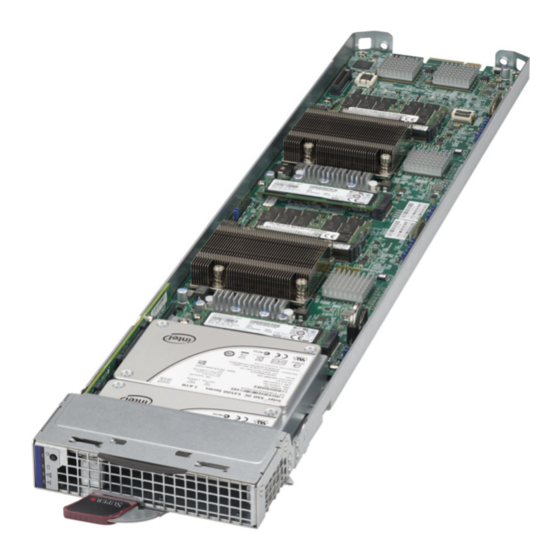
MBI-6219G-T8HX/MBI-6119G-T8HX MicroBlade Module User’s Manual Figure 4-7. Exploded View of a MBI-6219G-T8HX Blade Module Table 4-6. Main Components of a MBI-6219G-T8HX Blade Module Item Description Blade Unit/Module 2.5" SATA3 HDD/SSD Hard Drives Front Top Cover DIMM slots CPU/Heatsinks Hard Drive Backplane M.2 Ports SATA-DOM ports Memory Support... -
Page 49: Hard Disk Drives
Chapter 1 information on RAID Setup. WARNING: Enterprise level hard disk drives are recommended for use in Supermicro chassis and servers. For information on recommended HDDs, visit the Supermicro Web site http://www.supermicro.com/products/nfo/storage.cfm. Blade Power Consumption Page Using the Web-based Management Utility from the CMM module you may use the... - Page 50 MBI-6219G-T8HX/MBI-6119G-T8HX MicroBlade Module User’s Manual Notes 4-10...
-
Page 51: Chapter 5 Bios
Note: Due to periodic changes to the BIOS, some settings may have been added or deleted and might not yet be recorded in this manual. Please refer to the http:// www.supermicro.com/products/microblade/module/ web site for further details on BIOS setup and the BIOS menus for your MicroBlade module. -
Page 52: Bios Updates
However, it is recommended that you not update BIOS if you are not experiencing problems with a blade module. Updated BIOS files are located on our web site (http://www.supermicro.com/products/ microblade). Please check the current BIOS revision and make sure it is newer than your current BIOS before downloading. -
Page 53: Main Bios Setup
Chapter 5: BIOS While the BIOS is in control, the Setup program can be activated in one of two ways: 1. By pressing <D > immediately after turning the system on, or ELETE 2. When the message Press the <Delete> key to enter Setup appears briefly at the bottom of the screen during the POST, press the <D >... - Page 54 MBI-6219G-T8HX/MBI-6119G-T8HX MicroBlade Module User’s Manual Table 5-1. Main BIOS Setup Menu Options Menu Option Description Using the arrow keys, highlight the month, day and year fields, and enter the System Date correct data for the system date. Press the <Enter> key to save the data. To set the system date and time, key in the correct information in the appropriate System Time fields.
-
Page 55: Advanced Setup
Chapter 5: BIOS Advanced Setup Choose Advanced from the BIOS Setup Utility main menu with the arrow keys to display the A menu. The items with a triangle beside them are DVANCED ETUP sub-menus that can be accessed by highlighting the item and pressing <E >. - Page 56 MBI-6219G-T8HX/MBI-6119G-T8HX MicroBlade Module User’s Manual Table 5-3. Boot Feature Sub-menu Menu Option Description Use this feature to select the screen display between the POST messages and the OEM logo upon bootup. Select Disabled to display the POST Quiet Boot messages. Select Enabled to display the OEM logo instead of the normal POST messages.
- Page 57 Chapter 5: BIOS Table 5-4. CPU Configuration Sub-menu (Continued) Menu Option Description Use this setting to specify the number of cores to enable. Use the number Core’s Enabled pad “+” or “-” keys to specify a number up to 12. The number 0 means all cores with 12 cores available.
- Page 58 MBI-6219G-T8HX/MBI-6119G-T8HX MicroBlade Module User’s Manual Table 5-5. Chipset Configuration Sub-menu Menu Option Description North Bridge This sub-menu configures North Bridge features and shows configuration Configuration information. IIO Configuration Use this sub-menu to set IIO configuration features and optons. Set this option to allow DFX Lock Bits to remain clear. Options include EV DFX Features Enable and Disable.
- Page 59 Chapter 5: BIOS Table 5-5. Chipset Configuration Sub-menu (Continued) Menu Option Description IOU0 (IIO PCIe This setting selects PCIe port bifurcation for selected slot(s). Options Port 2) include x4x4x4x4, x4x4x8, x8x4x4, x8x8, x16 and Auto. IOU1 (IIO PCIe This setting selects PCIe port bifurcation for selected slot(s). Options Port 3) include x4x4x4x4, x4x4x8, x8x4x4, x8x8, x16 and Auto.
- Page 60 MBI-6219G-T8HX/MBI-6119G-T8HX MicroBlade Module User’s Manual Table 5-5. Chipset Configuration Sub-menu (Continued) Menu Option Description DRAM RAPL Use this setting to set the DRAM RAPL Baseline mode. Options include Baseline Disabled, DRAM RAPL Mode 0 and DRAM RAPL Mode 1. Use this setting to configure Thermal Throttling mode. Options include Set Throttling Mode Disabled and CLTT.
- Page 61 Chapter 5: BIOS Table 5-5. Chipset Configuration Sub-menu (Continued) Menu Option Description This setting enables or disables USB 3.0 (XHCI) controller support. USB3.0 Support Options include Smart Auto, Auto, Enabled or Disabled. This setting controls the USB EHCI (USB 2.0) functions. One EHCI EHCI1 controller must always be enabled.
- Page 62 MBI-6219G-T8HX/MBI-6119G-T8HX MicroBlade Module User’s Manual Table 5-8. Server ME Configuration Sub-menu Menu Option Description General ME Configuration General ME configuration information is displayed at the top of this screen. Information The altitude of the platform location above sea level, expressed in meters, Altitude is set using the keyboard’s number pad “+”...
- Page 63 Chapter 5: BIOS Table 5-9. PCIe/PCI/PnP Configuration Sub-menu (Continued) Menu Option Description This setting allocates MMIOH size per CPU. Options include 256G, 128G, MMIO High Size 512G and 1024G. CPU1 Slot 1 PCI-E This setting enables or disables the PCIe Slot OPROM option.Options OPROM include Disabled, Legacy or EFI.
- Page 64 MBI-6219G-T8HX/MBI-6119G-T8HX MicroBlade Module User’s Manual Table 5-11. Serial Port Console Redirection Sub-menu Menu Option Description COM1 Console Redirection, COM2/SOL/Legacy Console Redirection Sub-menus Select Enabled to enable console redirection support for a serial port Console Redirection specified by the user. The options are Enabled and Disabled. This feature allows the user to specify how the host computer will Console Redirection exchange data with the client computer, which is the remote computer...
- Page 65 Chapter 5: BIOS Table 5-11. Serial Port Console Redirection Sub-menu (Continued) Menu Option Description This feature selects the settings for Function Keys and KeyPad used for Putty KeyPad Putty, which is a terminal emulator designed for the Windows OS. The options are VT100, LINUX, XTERMR6, SC0, ESCN, and VT400.
- Page 66 MBI-6219G-T8HX/MBI-6119G-T8HX MicroBlade Module User’s Manual Table 5-12. ACPI Settings Sub-menu Menu Option Description This feature Enables the Windows Hardware Error Architecture (WHEA) support WHEA Support for the Windows 2008 (or a later vision) operating system. The options are Enabled and Disabled. Select Enabled to activate the High Performance Event Timer (HPET) that produces periodic interrupts at a much higher frequency than a Real-time Clock (RTC) does in synchronizing multimedia streams, providing smooth playback...
-
Page 67: Event Logs Setup
Chapter 5: BIOS Event Logs Setup Table 5-15. Event Logs Menu Menu Option Description Change SMBIOS This sub-menu allows you to change the SMBIOS Event Log configuration Event Log Settings settings. Change this setting to enable or disable all features of the SMBIOS Event Logging during system boot. -
Page 68: Ipmi Setup
MBI-6219G-T8HX/MBI-6119G-T8HX MicroBlade Module User’s Manual IPMI Setup Table 5-16. IPMI Menu Menu Option Description IPMI Information This item indicates the IPMI firmware revision used in your system. Use this sub-menu to configure the System Event Log. System Event Log NOTE: All values changed here in this sub-menu do not take effect until the computer is restarted. -
Page 69: Security
Chapter 5: BIOS Security Choose Security from the BIOS Setup main menu with the arrow keys to bring up the menu. Security setting options are displayed by highlighting the setting ECURITY ETUP using the arrow keys and pressing <E >. All Security BIOS settings are described in NTER Table 5-17 below. -
Page 70: 5-10 Save & Exit
MBI-6219G-T8HX/MBI-6119G-T8HX MicroBlade Module User’s Manual 5-10 Save & Exit Choose S & E from the 128 MB SPI Flash EEPROM with AMI® BIOS BIOS Setup Utility main menu with the arrow keys to display the S & E menu. All Exit ETUP BIOS settings are described in Table 5-19... -
Page 71: Appendix Aami Uefi Bios Post Codes
Appendix A AMI UEFI BIOS POST Codes A status code is a data value used to indicate progress during the boot phase. A subset of these status codes, known commonly as checkpoints, indicate common phases of the BIOS boot process. Checkpoints are typically output to I/O port 80h, but Aptio 4.x core can be configured to send status codes to a variety of sources. -
Page 72: Standard Checkpoints
MBI-6219G-T8HX/MBI-6119G-T8HX MicroBlade Module User’s Manual Standard Checkpoints Table A-2. SEC Phase Codes Description Status Code 0x00 Not Used Progress Codes 0x01 Power on. Reset type detection (soft/hard). 0x02 AP initialization before microcode loading 0x03 North Bridge initialization before microcode loading 0x04 South Bridge initialization before microcode loading 0x05... - Page 73 Table A-3. PEI Phase Status Codes Description 0x19 Pre-memory South Bridge initialization is started 0x1A Pre-memory South Bridge initialization (South Bridge module specific) 0x1B Pre-memory South Bridge initialization (South Bridge module specific) 0x1C Pre-memory South Bridge initialization (South Bridge module specific) 0x1D –...
- Page 74 MBI-6219G-T8HX/MBI-6119G-T8HX MicroBlade Module User’s Manual Table A-3. PEI Phase Status Codes Description 0x53 Memory initialization error. No usable memory detected 0x54 Unspecified memory initialization error. 0x55 Memory not installed 0x56 Invalid CPU type or Speed 0x57 CPU mismatch 0x58 CPU self test failed or possible CPU cache error 0x59 CPU micro-code is not found or micro-code update is failed 0x5A...
- Page 75 Table A-3. PEI Phase Status Codes Description 0xFA Invalid recovery capsule 0xFB – 0xFF Reserved for future AMI error codes Table A-4. PEI Beep Codes # of Beeps Description Memory not Installed Memory was installed twice (InstallPeiMemory routine in PEI Core called twice) Recovery started DXEIPL was not found...
- Page 76 MBI-6219G-T8HX/MBI-6119G-T8HX MicroBlade Module User’s Manual Table A-5. DXE Phase Status Codes Description 0x70 South Bridge DXE initialization is started 0x71 South Bridge DXE SMM initialization is started 0x72 South Bridge devices initialization 0x73 South Bridge DXE Initialization (South Bridge module specific) 0x74 South Bridge DXE Initialization (South Bridge module specific) 0x75...
- Page 77 Table A-5. DXE Phase Status Codes Description 0xA5 SCSI Reset 0xA6 SCSI Detect 0xA7 SCSI Enable 0xA8 Setup Verifying Password 0xA9 Start of Setup 0xAA Reserved for ASL (see ASL Status Codes section below) 0xAB Setup Input Wait 0xAC Reserved for ASL (see ASL Status Codes section below) 0xAD Ready To Boot event 0xAE...
- Page 78 MBI-6219G-T8HX/MBI-6119G-T8HX MicroBlade Module User’s Manual Table A-5. DXE Phase Status Codes Description 0xDA Boot Option is failed (StartImage returned error) 0xDB Flash update is failed 0xDC Reset protocol is not available Table A-6. DXE Beep Codes # of Beeps Description Invalid password Some of the Architectural Protocols are not available No Console Output Devices are found...
-
Page 79: Oem-Reserved Checkpoint Ranges
OEM-Reserved Checkpoint Ranges Table A-8. OEM-Reserved Checkpoint Ranges Status Codes Description 0x05 OEM SEC initialization before microcode loading 0x0A OEM SEC initialization after microcode loading 0x1D – 0x2A OEM pre-memory initialization codes 0x3F – 0x4E OEM PEI post memory initialization codes 0x80 –... - Page 80 MBI-6219G-T8HX/MBI-6119G-T8HX MicroBlade Module User’s Manual A-10...
- Page 81 Disclaimer The products sold by Supermicro are not intended for and will not be used in life support systems, medical equipment, nuclear facilities or systems, aircraft, aircraft devices, aircraft/emergency communication devices or other critical systems whose failure to perform be reasonably expected to result in significant injury or loss of life or catastrophic property damage.
- Page 82 MBI-6219G-T8HX/MBI-6119G-T8HX MicroBlade Module User’s Manual MBI-6219G-T8HX/MBI-6119G-T8HX...
Need help?
Do you have a question about the MicroBlade MBI-6219G-T8HX and is the answer not in the manual?
Questions and answers