Table of Contents
Advertisement
Quick Links
Advertisement
Table of Contents

Related Manuals for Bruker 300'154 Ascend DNP


Summary of Contents for Bruker 300'154 Ascend DNP
- Page 1 300‘154 Ascend DNP User Manual Version Innovation with Integrity...
- Page 2 © April 9, 2015: Bruker Corporation Faellanden, Switzerland ZTKS0269 / Z33108 / 02 For further technical assistance on the NMR Magnet System, please do not hesitate to contact your nearest BRUKER dealer or contact us directly at: BRUKER BioSpin AG Industriestrasse 26 CH–8117 Faellanden Switzerland...
-
Page 3: Table Of Contents
Table of Contents Contact ......................7 Introduction....................9 General Information....................9 Limitation of Liability ....................9 Customer Service..................... 9 Warranty........................9 Copyright ........................9 General View......................10 Safety......................11 Approved Persons....................11 Customer Responsibilities..................12 Key Words......................13 Residual Risks......................14 2.4.1 Persons ........................14 2.4.2 Intended Use ...................... - Page 4 Table of Contents Sweep Procedure (DNP only) ................36 Set into Operation....................37 Troubleshooting ..................39 Safety ........................39 Problem ........................40 6.2.1 During Transportation..................... 40 6.2.2 During Assembling ....................40 6.2.3 During Cooling Down....................42 6.2.4 During Energizing and Shimming ................46 6.2.5 During Operation of the Magnet Stand..............
- Page 5 Table of Contents 9.13.3 Wiring Diagram Magnet Control ................77 9.13.4 Wiring Diagram Magnet Diagnostic and Temperature Sensors ......78 9.13.5 Shorting Plug......................79 9.13.6 Sweep Current Lead Mounting Device..............80 9.14 Resistance at Room Temperature ................. 81 9.15 Sweep Current Lead Resistance................82 9.16 Heater Currents......................
- Page 6 Table of Contents ZTKS0269 / Z33108 / 02...
-
Page 7: Contact
Contact Manufacturer Bruker BioSpin AG Industriestrasse 26 CH–8117 Faellanden Switzerland Phone: + 41 44 825 91 11 Fax: + 41 44 825 96 96 http://www.bruker.com E-mail: magnetics@bruker.ch Please refer to the Model No., Serial No. and Internal Order No. in all correspondence regarding the NMR system or components thereof. - Page 8 Contact ZTKS0269 / Z33108 / 02...
-
Page 9: Introduction
• arbitrary changes or modifications and • use of not approved spare parts or accessories. Customer Service Technical support is provided by Bruker Service via telephone or e-mail. For contact information see page 7 of this document. Warranty The warranty terms can be found in the sales documents of the magnet system and in the Terms and Conditions of Bruker BioSpin AG. -
Page 10: General View
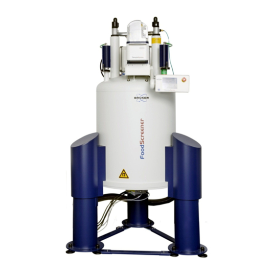
Introduction General View 1 Magnet Stand 2 RT Vessel 3 RT Bore 4 Nitrogen Turrets 5 Heat Exchanger 6 Nitrogen Flow System 7 Helium Flow System 8 Current Lead Turret 9 Helium Fill-in Turret with helium fill-in port Figure 1.1: General View of a Magnet System with 2 Helium Turrets The heart of the NMR magnet system is a superconducting magnet located inside the helium vessel, which is filled with liquid helium. -
Page 11: Safety
The supplied cryostat and further equipment of the magnet system were designed and manufactured according to best available technical knowledge and practice, achieved in over 50 years of experience of the Bruker Corporation. International standards for quality and approval recommended for cryostats of superconducting magnets were certified. -
Page 12: Customer Responsibilities
Safety Customer Responsibilities The customer must obey the security advice and the rules for safety, applicable local accident prevention and environmental protection correctly for the magnet system. Furthermore, the customer is responsible for keeping the magnet system in good technical condition. In particular: •... -
Page 13: Key Words
Safety Key Words Safety instructions in this manual are marked with symbols. The safety instructions are introduced using indicative words which express the extent of the hazard. In order to avoid accidents, personal injury or damage to property, always observe safety instructions and proceed with care. -
Page 14: Residual Risks
Do not exceed specified values for operating the magnet system. • Do not use inserts inside the RT bore not approved by Bruker Service. Damage claims from damages caused by other than the intended use of the magnet system are excluded and the customer is held liable. -
Page 15: Safety Devices
Safety 2.4.3 Safety Devices WARNING Risk of damage to life and limb due to not sufficient safety devices. Several safety devices ensure safe operation of the magnet system. They must always be in correct working condition. Thus: • Do not block safety devices. •... -
Page 16: Signs And Labels
Thus: • Maintain signs and labels in a readable state. • Replace damaged or not readable signs and labels immediately. New signs and labels can be ordered from Bruker Service. 2.4.6 Technical Risks Magnetic Field WARNING Risk of damage to life and limb due to high magnetic fields. - Page 17 Contact with the eyes may cause blindness. Refer to Warning: Low Temperature on page 17. Thus: • Only use cryogenic agents in well ventilated rooms. In case of doubt ask Bruker Service. • Wear an oxygen monitor on the body during service and maintenance work.
- Page 18 The evaporating helium will displace the breathing air. In case of not sufficient ventilation this may result in death by suffocation. Thus • The magnet system site must be well ventilated. In case of doubt contact Bruker Service. • The evaporating gas may resemble smoke. Never pour water on the magnet system.
-
Page 19: Slippage
Safety Low Temperatures WARNING Risk of injury due to low temperatures of liquids and metal parts. Physical contact with extremely cold liquids and metal parts may cause serious injuries. Contact with the skin may cause cold burns. Contact with the eyes may cause blindness. - Page 20 Safety Risk of Tilting WARNING Risk of injury due to tilting of the magnet system. The magnet system is very sensitive to lateral forces. It may tilt. Thus: • Do not climb onto the magnet system. • Do not lean items against the magnet system. •...
- Page 21 Safety Transportation CAUTION Risk of injury and property damage due to incorrect transportation. The boxes may tilt, movement may get out of control. Thus persons may get injured and the cryostat or further equipment may be damaged. Thus: • Be careful while unloading and moving the boxes. •...
-
Page 22: Personal Protective Equipment
Safety Personal Protective Equipment The personal protective equipment must be worn at any time while working on the magnet system and further equipment to prevent health hazards. Protective Goggles Used to protect the eyes from injury due to flying cold liquids and parts. Protective Gloves Used to protect the hands from injury caused by contact with extremely cold liquids or surfaces and for protection from injury caused by rough edges. -
Page 23: Description Of Signs And Labels
Safety Description of Signs and Labels Signs and labels are always related to their immediate vicinity. The following signs and labels are found on the magnet system and in the vicinity. Prohibition sign: No person with pacemakers! People with pacemakers are endangered in the identified area of 0.5 mT (5 Gauss) and are not allowed to enter these areas. -
Page 24: Safety Devices
Safety Safety Devices The supplied cryostat of the magnet system is equipped with the following safety devices: 1 Drop-off Plate 2 One-way Valve of the nitrogen vessel 3 Safety Valve of the nitrogen vessel 4 One-way Valve of the helium vessel 5 Quench Valves Figure 2.1: Safety Devices of the Cryostat with 2 Helium Turrets ZTKS0269 / Z33108 / 02... - Page 25 Safety Quench Valve The quench valves (5) are the safety devices of the helium vessel. They open with a defined pressure. In case of an accidental overpressure in the helium vessel the quench valves will release the pressure smoothly. Safety Valve The safety valve (3) is the safety device of the nitrogen vessel.
-
Page 26: Behavior In Danger And Emergency Situations
Safety Behavior in Danger and Emergency Situations Preparations • Keep the emergency exits free at all times. • Prepare and maintain an up-to-date list of emergency telephone numbers in the magnet system area. In Case of Emergency • Leave the danger zone immediately. •... -
Page 27: Transportation
Transportation Safety The transportation is carried out by Bruker Service or approved persons. However, it may happen that other persons have to receive the delivery of the shipping boxes. In this case it is essential to obey the instructions in this chapter and to inform these persons before. -
Page 28: Disposal
• Contact Bruker Service before installation. The claim for damage expires after the fixed period. Thus: Report damages to Bruker Service immediately after detection of damage. For contact information see page 7 of this document. ZTKS0269 / Z33108 / 02... -
Page 29: Transportation By Fork Lift / Pallet Jack
Transportation Transportation by Fork Lift / Pallet Jack A fork lift is recommended for transporting the boxes to the installation site. Approved Persons: Approved forklift / pallet jack operator Precondition: The fork lift / pallet jack must be approved for the transportation weight (see ”Weights”... -
Page 30: Transportation With A Crane
Transportation Transportation with a Crane A crane is recommended for lifting the cryostat out of the box. Approved Persons: Approved crane operator Precondition: The crane must be approved for the transportation weight (see ”Weights” on page 60 ”Dimensions for Transportation” on page 60). -
Page 31: Storing
Storage temperature: 5 - 40 °C. • Storage humidity: less than 50% @ 23 °C. Disposal For disposal after the life cycle please contact Bruker Service for further information. For contact information see page 7 of this document. ZTKS0269 / Z33108 / 02... - Page 32 Transportation ZTKS0269 / Z33108 / 02...
-
Page 33: Assembling
Assembling Safety Approved Persons: Bruker Service only ZTKS0269 / Z33108 / 02... - Page 34 Assembling ZTKS0269 / Z33108 / 02...
-
Page 35: Operation
Operation Safety Approved Persons Bruker Service, Approved Customer Personnel WARNING Magnetic Field (see page Cryogenic Agents (see page Electricity (see page Gas under Pressure (see page ZTKS0269 / Z33108 / 02... -
Page 36: Sweep Procedure (Dnp Only)
Operation Sweep Procedure (DNP only) Check the settings of the Sweep Power Supply (see ”Sweep Power Supply Set- tings” on page 82). If necessary change settings (refer to the supplied manual of the Sweep Power Supply). Set the output current at the Sweep Power Supply to 0 A. WARNING Risk of a quench, if currents at the Sweep Power Supply and sweep coil are different. -
Page 37: Set Into Operation
Operation Set into Operation If the magnet system is equipped with a magnet stand with pneumatic isolators: Set the magnet stand into operation by switching the pneumatic controller to UP position. Figure 5.1: Start the Magnet Stand For any work at the magnet system like maintenance or refill of cryogenic agents stop the magnet stand by switching the pneumatic controller to DOWN position. - Page 38 Operation ZTKS0269 / Z33108 / 02...
-
Page 39: Troubleshooting
Troubleshooting Troubleshooting must be performed only with approved qualification. In case of doubts or problems not specified in the following list contact Bruker Service immediately. For contact information see page 7of this manual. Safety Approved Persons Bruker Service, Approved Customer Personnel... -
Page 40: Problem
6.2.2 During Assembling Indicator Possible reason Solution Ceiling height too Site does not meet Choose another site that Bruker Service low for assembling the required meets the required on magnet stand. conditions. conditions. Ceiling height too Site does not meet... - Page 41 For this work the bottom plate has to be removed. Check the suspension tubes of the helium vessel are not broken. Install the safety device for fall protection (not supplied). Contact Bruker Service for further information.
-
Page 42: During Cooling Down
Troubleshooting 6.2.3 During Cooling Down Indicator Possible reason Solution Cooling with liquid Empty transpor- Refill or replace transportation Bruker Service nitrogen continues tation dewar. dewar. too slowly. Transfer pressure Increase transfer pressure Bruker Service too low. slightly (max. pressure 0.3 bar). - Page 43 Continued from page before Indicator Possible reason Solution • Do not remove pumping RT vessel becomes Vacuum is broken or Bruker Service unit until filling with liquid cold and wet. less than 10 mbar. is finished. • Continue as in problem...
- Page 44 Continued from page before Indicator Possible reason Solution Warm up the magnet coil Nitrogen ice in the Times between Bruker Service with warm helium gas helium vessel. pumping and through the precooling flushing were too tube until the whole coil is long;...
- Page 45 Continued from page before Indicator Possible reason Solution The zero reading of The Helium Level Check the connection in the Bruker Service the Helium Level Sensor is not helium fill-in turret between Sensor can not be connected correctly Helium Level Sensor and...
-
Page 46: During Energizing And Shimming
During Energizing and Shimming Indicator Possible reason Solution The current lead can The connector is Carefully remove the ice with Bruker Service not be inserted covered with ice warm helium gas. completely into the (frozen moisture or Use the dipstick or the connector. - Page 47 Continued from page before Indicator Possible reason Solution Shorting plug can The connector is Carefully remove the ice with Bruker Service not be removed. covered with ice warm helium gas. Use the (frozen moisture or dipstick or the precooling tube nitrogen ice).
-
Page 48: During Operation Of The Magnet Stand
Repeat shimming. 6.2.5 During Operation of the Magnet Stand In case of doubt contact Bruker Service and refer to the manual of the Magnet Stand. Indicator Possible reason Solution The NMR spectrum Pneumatic controller... - Page 49 5 to 8 bar Personnel (70 to 112 psi). If the problem is still not Approved solved, contact Customer Bruker Service. Personnel The magnet system Stop the pneumatic isolators. Bruker Service is not leveled Check the leveling of the correctly.
-
Page 50: During Standard Operation
Approved decreases to zero. pressure is Watch helium boil off daily. Customer increasing. Personnel The helium flow Contact Bruker Service Approved system is covered immediately! Do not try to Customer with ice. remove ice of the helium flow Personnel system! - Page 51 Quench. Loss of supercon- ”After a Quench” on Approved ductivity. page Customer Contact Bruker Service Personnel immediately! Cold spots within the Alignment of the Contact Bruker Service. Approved RT bore. vessels not correct. Customer...
-
Page 52: During De-Energizing And Warming Up
During De-energizing and Warming up Indicator Possible reason Solution The magnet system The helium level was Refill helium at least to the Bruker Service quenches during too low for minimum allowed level (see de-energizing. de-energizing. ”Helium Level Graph” on page 66). -
Page 53: After A Quench
The stored magnetic energy is converted into heat, which promotes rapid evapora- tion of large quantities of helium. If a quench occurs contact Bruker Service immediately. Figure 6.1: Magnet system during a quench WARNING... - Page 54 Troubleshooting ZTKS0269 / Z33108 / 02...
-
Page 55: Maintenance
Maintenance Maintenance must be performed only with approved qualification. In case of doubt contact Bruker Service. For contact information see page 7 of this document. Safety Approved Persons Bruker Service, Approved Customer Personnel WARNING Magnetic Field (see page Cryogenic Agents (see... -
Page 56: Cleaning
Procedure respecting the warnings and instructions given there. • Record the filling session. Deviation from estimated consumption may be used for identification of troubles. In this case contact Bruker Service. • Check the nitrogen level. weekly Cryostat Approved Customer •... -
Page 57: Disassembling
Disassembling Safety Approved Persons: Bruker Service only ZTKS0269 / Z33108 / 02... - Page 58 Disassembling ZTKS0269 / Z33108 / 02...
-
Page 59: Technical Data Ms 300'154 Ascend Dnp
Technical Data MS 300‘154 Ascend DNP Environmental Conditions Value Unit Minimum surrounding temperature °C Maximum surrounding temperature °C Maximum relative humidity up to 31 °C Maximum relative humidity between 31 °C and 40 °C 80 – 50 linearly decreasing Table 9.1: Environmental conditions Identification Plate The identification plate is on the right rear side attached to the bottom plate of the... -
Page 60: Dimensions
Technical Data MS 300‘154 Ascend DNP Dimensions 9.3.1 Weights Value Unit Weight magnet system (empty, without magnet stand, without compressor package) Weight magnet system (completely filled, without magnet stand) Operational weight (completely filled with magnet stand) Weight magnet stand Weight magnet stand (ready for transportation, including box) Weight magnet system (empty, ready for transportation, including box and transportation locks) Table 9.2:... -
Page 61: Dimensions Cryostat
Technical Data MS 300‘154 Ascend DNP 9.3.3 Dimensions Cryostat Front View Figure 9.1: Dimensions of the cryostat (front view) ZTKS0269 / Z33108 / 02... - Page 62 Technical Data MS 300‘154 Ascend DNP Dimensions Cryostat Value Unit 4000 Operational Ceiling Height D-RT Diameter RT Bore Tube Diameter RT vessel Diameter Bottom Plate 1205 Height Cryostat (bottom plate to top flange) 1604 Height Cryostat (minimum height for transportation) 1763 Height Cryostat (bottom plate to flow system) 1050...
- Page 63 Technical Data MS 300‘154 Ascend DNP Top View Figure 9.2: Dimensions of the cryostat (top view) Cryostat Dimensions Value Unit 1236 1116 1375 Table 9.5: Dimensions of the cryostat – top view 1. Keep at least an additional free space of 1.5 m around the magnet system for service. ZTKS0269 / Z33108 / 02...
-
Page 64: Filling Volume, Evaporation Rate And Hold Time
Technical Data MS 300‘154 Ascend DNP Filling Volume, Evaporation Rate and Hold Time Cryogenic Agents Value Unit Nitrogen vessel total volume Nitrogen refill volume Nitrogen evaporation rate ml/h Nitrogen hold time > 14 days Helium vessel total volume Helium refill volume Helium evaporation rate (sweep coil in persistent mode) ml/h Helium hold time... -
Page 65: Nitrogen Level Graph
Technical Data MS 300‘154 Ascend DNP Nitrogen Level Graph Figure 9.3: Nitrogen Level Graph ZTKS0269 / Z33108 / 02... -
Page 66: Helium Level Graph
Technical Data MS 300‘154 Ascend DNP Helium Level Graph Figure 9.4: Helium Level Graph ZTKS0269 / Z33108 / 02... -
Page 67: Nitrogen Level Sensor
Technical Data MS 300‘154 Ascend DNP Nitrogen Level Sensor The Nitrogen Level Sensor is inserted in the recommended nitrogen turret. 6 lights display the nitrogen level. Nitrogen Level Sensor Material No. Value Unit Level Sensor Type Z122404 12/1126/860 Diameter Overall length 1126 Active length Table 9.7:... -
Page 68: Helium Level Sensor
Technical Data MS 300‘154 Ascend DNP Helium Level Sensor The Helium Level Sensor is inserted in the helium fill-in turret. Helium Level Sensor Material No. Value Unit Level Sensor Type Z58103 1500/874 Overall length 1517 Active length Calibration 0 %, Calibration resistor Z53168 Ω... -
Page 69: Temperature Sensors
Technical Data MS 300‘154 Ascend DNP Temperature Sensors The temperature sensors (PT 100 and IBT) are used to monitor the temperature of the magnet during cooling down and warming up the magnet system. PT 100 Sensor Measure the resistance with a maximum current of 1 mA. Temperature Unit Resistance... - Page 70 Technical Data MS 300‘154 Ascend DNP IBT Carbon Resistor Measure the resistance with a maximum current of 1 mA. Temperature Unit Resistance Unit Room Temperature Ω Liquid Nitrogen Ω Ω Ω Ω Ω Ω Ω Liquid Helium Ω Table 9.10: Characteristic Values of IBT Carbon Sensor Figure 9.8: Characteristic Curve of IBT Carbon Sensor ZTKS0269 / Z33108 / 02...
-
Page 71: Technical Data Magnet
Technical Data MS 300‘154 Ascend DNP 9.10 Technical Data Magnet Technical Data Magnet Value Unit Proton frequency Central field 7.05 Coil inductance 52.2 Magnetic energy 494.9 Maximum drift rate 0.01 ppm/h Hz/h Table 9.11: Specification of the Magnet Operating Modes of the Magnet System: Driven Mode In the driven mode the current lead is mounted and the electricity is flowing through the power supply. -
Page 72: Fringe Field Plot
Technical Data MS 300‘154 Ascend DNP 9.11 Fringe Field Plot Figure 9.9: Fringe field plot of the magnet system at maximum field Fringe Field Unit R max Unit Z max Unit inside cryostat 0.52 0.66 1.11 0.72 1.25 0.98 1.66 0.5 (5 Gauss) 1.25 2.00... -
Page 73: Technical Data Sweep Coil
Technical Data MS 300‘154 Ascend DNP 9.12 Technical Data Sweep Coil Technical Data Sweep Coil Value Unit Sweep coil strength 32.5 Maximum sweep coil current range ± 20 Maximum sweep coil field ± 650 Helium evaporation rate (sweep coil in driven mode, 20 A) 1500 ml/h Table 9.13: Specification of the Sweep Coil... -
Page 74: Current Lead
Technical Data MS 300‘154 Ascend DNP 9.13 Current Lead Figure 9.10: Current Lead 55 pin ZTKS0269 / Z33108 / 02... -
Page 75: Sweep Current Lead
Technical Data MS 300‘154 Ascend DNP 9.13.1 Sweep Current Lead Figure 9.11: Sweep Current Lead 55 pin ZTKS0269 / Z33108 / 02... -
Page 76: Wiring Diagram Magnet
Technical Data MS 300‘154 Ascend DNP 9.13.2 Wiring Diagram Magnet Figure 9.12: Wiring Diagram Magnet ZTKS0269 / Z33108 / 02... -
Page 77: Wiring Diagram Magnet Control
Technical Data MS 300‘154 Ascend DNP 9.13.3 Wiring Diagram Magnet Control Figure 9.13: Wiring Diagram Magnet Control ZTKS0269 / Z33108 / 02... -
Page 78: Wiring Diagram Magnet Diagnostic And Temperature Sensors
Technical Data MS 300‘154 Ascend DNP 9.13.4 Wiring Diagram Magnet Diagnostic and Temperature Sensors Figure 9.14: Wiring Diagram Magnet - Diagnostic and Temperature Sensors ZTKS0269 / Z33108 / 02... -
Page 79: Shorting Plug
Technical Data MS 300‘154 Ascend DNP 9.13.5 Shorting Plug Remove the shorting plug before inserting the current lead or the sweep current lead. Figure 9.15: Shorting Plug 55 pin 1 Shorting Plug Tool for fitting and removing the shorting plug 2 Shorting Plug 3 Shorting Plug –... -
Page 80: Sweep Current Lead Mounting Device
Technical Data MS 300‘154 Ascend DNP 9.13.6 Sweep Current Lead Mounting Device Insert the sweep current lead after removing the current lead. Figure 9.16: Sweep Current Lead Mounting Device M 16 socket ZTKS0269 / Z33108 / 02... -
Page 81: Resistance At Room Temperature
Technical Data MS 300‘154 Ascend DNP _ _ _ʹ_ _ _ʹ_ _ _ 9.14 Resistance at Room Temperature Current lead used to energize magnet: Current Lead, 55 Pin High Current Lead and High HTS Current Lead, 55 Pin ○ 200 A (grey) ○... -
Page 82: Sweep Current Lead Resistance
Technical Data MS 300‘154 Ascend DNP _ _ _ʹ_ _ _ʹ_ _ _ _ 9.15 Sweep Current Lead Resistance Connector Description Value Unit From: B, J, C, D 10 Pin Sweep Sweep Coil +/– Ω G, H, F, K 10 Pin Sweep From: 10 Pin Sweep Sweep Coil Heater... -
Page 83: Shim Switch Heater
Technical Data MS 300‘154 Ascend DNP _ _ _ʹ_ _ _ʹ_ _ _ _ 9.18 Shim Switch Heater Heater operation during energizing / deenergizing Shim Heater Operation Switch ..automatic permanent automatic automatic automatic automatic automatic automatic –Y automatic... -
Page 84: Energizing Assignment And Currents
Check the “minimum level during energizing” (see "Helium Level Graph" on page 66). Energizing Currents [A] Sense Voltage Remarks Bruker Test Site [mV] Pause ..at ..MHz Overshoot ( % of final current) -
Page 85: Magnetic Center
Technical Data MS 300‘154 Ascend DNP _ _ _ʹ_ _ _ʹ_ _ _ _ 9.20 Magnetic Center Magnetic Center Value Unit Distance magnetic center from top flange (MCT) Distance magnetic center from bottom flange (MCB) Shimsystem Offset (SO) see Figure 9.17: and refer to the supplied Test Protocol AST Table 9.20: Magnetic center Magnetic Center... -
Page 86: Cycling Assignment And Shim Currents
Technical Data MS 300‘154 Ascend DNP _ _ _ʹ_ _ _ʹ_ _ _ _ 9.21 Cycling Assignment and Shim Currents Shim Currents Value Unit Time between energizing and cycling Shim current rate A/min Z0 Shim current Shim current Shim current Shim current X Shim current Y Shim current... -
Page 87: Energizing Currents
Technical Data MS 300‘154 Ascend DNP _ _ _ʹ_ _ _ʹ_ _ _ _ 9.22 Energizing Currents Energizing Currents Value at Value at Value at Value at Unit Customer Customer Customer Customer Site #1 Site #2 Site #3 Site #4 Magnet main current Z0 Shim current Shim current... -
Page 88: Deenergizing Assignment And Currents
Technical Data MS 300‘154 Ascend DNP 9.23 Deenergizing Assignment and Currents Deenergizing Currents Sense Voltage Remarks Bruker Test Site [mV] 1000 2000 Total deenergizing time [min] 4000 Table 9.23: Deenergizing assignment and currents ZTKS0269 / Z33108 / 02... -
Page 89: Nitrogen Refill Report
Technical Data MS 300‘154 Ascend DNP 9.24 Nitrogen Refill Report Nitrogen level Nitrogen level Refill Volume Date, Time Signature before refill [%] after refill [%] ZTKS0269 / Z33108 / 02... - Page 90 Technical Data MS 300‘154 Ascend DNP Table continued Nitrogen level Nitrogen level Refill Volume Date, Time Signature before refill [%] after refill [%] ZTKS0269 / Z33108 / 02...
-
Page 91: Helium Refill Report
Technical Data MS 300‘154 Ascend DNP 9.25 Helium Refill Report Helium level Helium level Refill Volume Date, Time Signature before refill [%] after refill [%] ZTKS0269 / Z33108 / 02... - Page 92 Technical Data MS 300‘154 Ascend DNP Table continued Helium level Helium level Refill Volume Date, Time Signature before refill [%] after refill [%] ZTKS0269 / Z33108 / 02...
-
Page 93: A Appendix
Appendix Appendix Warning Signs Safety Instructions Key Word and Symbol .................. 13 Danger Key Word and Symbol .................. 13 Warning Safety Devices ....................15 Signs and Labels ................... 16 Slippage ......................19 Spare Parts ....................15 Spontaneous Ignition and Explosion ............. 19 Cryogenic Agents .................. - Page 94 Appendix ZTKS0269 / Z33108 / 02...
-
Page 95: Figures
Appendix Figures Figure 1.1: General View of a Magnet System with 2 Helium Turrets ....10 Figure 2.1: Safety Devices of the Cryostat with 2 Helium Turrets......24 Figure 3.1: Packaging (without surrounding panels)..........27 Figure 3.2: Transportation by Forklift - front side ........... 29 Figure 3.3: Transportation by Forklift - rear side ............ - Page 96 Appendix ZTKS0269 / Z33108 / 02...
-
Page 97: Glossary / Abbreviations
Appendix Glossary / Abbreviations Glossary Description Cryostat The collective of all parts providing a temperature of 4 K inside for the superconducting magnet. The cryostat also provides the safety devices and the access ports for the cryogenic agents and electricity. The superconducting magnet inside the cryostat is not energized. - Page 98 Appendix ZTKS0269 / Z33108 / 02...
-
Page 99: Index
Index Index Portable Oxygen Monitor ....22 Protective Clothes ......22 Access Point ........72 Protective Gloves ......22 Attachment Points ......30 Protective Goggles ......22 PT 100 Sensor ........69 Cleaning Staff ........12 Complaint Process ......28 Quench ........ - Page 100 Index ZTKS0269 / Z33108 / 02...
- Page 101 Revision History List Index: Date: Alteration Type: December First release. 2013 April 2015 Update helium level plot; inserted shimsystem offset and shim switch heater operation. ZTKS0269 / Z33108 / 02...
- Page 102 Bruker Corporation info@bruker.com www.bruker.com Order No: Z33108...
Need help?
Do you have a question about the 300'154 Ascend DNP and is the answer not in the manual?
Questions and answers