Sign In
Upload
Download
Table of Contents
Contents
Add to my manuals
Delete from my manuals
Share
URL of this page:
HTML Link:
Bookmark this page
Add
Manual will be automatically added to "My Manuals"
Print this page
×
Bookmark added
×
Added to my manuals
Manuals
Brands
Alfa Laval Manuals
Industrial Equipment
AQ1
Instruction manual
Alfa Laval AQ1 Instruction Manual
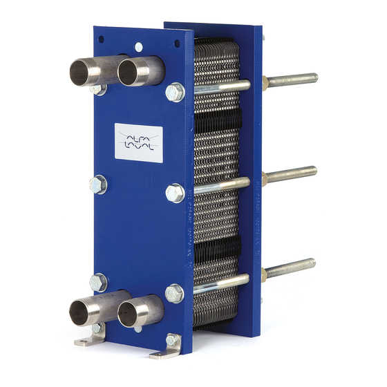
Gasketed plate-and-frame heat exchangers
Hide thumbs
Also See for AQ1
:
Instruction manual
(27 pages)
1
2
3
4
Table Of Contents
5
6
7
8
9
10
11
12
13
14
15
16
17
18
19
20
21
22
23
24
25
26
27
28
29
30
31
32
33
34
35
36
37
38
39
40
41
42
43
44
45
46
page
of
46
Go
/
46
Contents
Table of Contents
Bookmarks
Table of Contents
Table of Contents
1 Preface
Conditions and Requirements
Environmental Compliance
2 Safety
Safety Considerations
Definitions of Expressions
3 Description
Components
Name Plate
Function
Multi-Pass
Identification of Plate Side
4 Installation
Before Installation
Requirements
Lifting
Raising
5 Operation
Start-Up
Unit in Operation
Shut-Down
6 Maintenance
Cleaning - Non-Product Side
Opening
Bolt Configuration
Opening Procedure
Manual Cleaning of Opened Units
Deposits Removable with Water and Brush
Deposits Not Removable with Water and Brush
Closing
Pressure Test after Maintenance
Regasketing
Clip-On / Clipgrip
Glued Gaskets
Advertisement
Quick Links
Download this manual
Gasketed plate-and-frame heat exchangers
AQ line - AQ1, AQ1A, AQ1L, AQ2, AQ2A, AQ2L, AQ2S, AQ2T, AQ3, AQ4, AQ4T
Instruction Manual
Lit. Code 200000284-1-EN-GB
Table of
Contents
Previous
Page
Next
Page
1
2
3
4
5
Advertisement
Table of Contents
Need help?
Do you have a question about the AQ1 and is the answer not in the manual?
Ask a question
Questions and answers
Related Manuals for Alfa Laval AQ1
Industrial Equipment Alfa Laval T2 Instruction Manual
Heating insulation for gasketed plate heat exchangers (27 pages)
Industrial Equipment Alfa Laval AQ14 Instruction Manual
Gasketed plate-and-frame heat exchangers (48 pages)
Industrial Equipment Alfa Laval AQ Series Instruction Manual
Gasketed plate heat exchangers (46 pages)
Industrial Equipment Alfa Laval AQ2T-BZM Instruction Manual
Gasketed plate-and-frame (40 pages)
Industrial Equipment Alfa Laval T6 Instruction Manual
Cooling insulation for gasketed plate heat exchangers (26 pages)
Industrial Equipment Alfa Laval AC Series Instruction Manual
Brazed plate heat exchangers (26 pages)
Industrial Equipment Alfa Laval AXP Series Instruction Manual
Brazed plate heat exchangers (26 pages)
Industrial Equipment Alfa Laval AlfaNova 14 Instruction Manual
Fusion plate heat exchangers (12 pages)
Industrial Equipment Alfa Laval AlfaNova 76 Instruction Manual
Fusion plate heat exchangers (260 pages)
Industrial Equipment Alfa Laval ALS Series Instruction Manual
Agitator shut down seal (50 pages)
Industrial Equipment Alfa Laval AC Instruction Manual
Brazed and gas-to-liquid plate heat exchangers (33 pages)
Industrial Equipment Alfa Laval AXP Instruction Manual
Brazed and gas-to-liquid plate heat exchangers (33 pages)
Industrial Equipment Alfa Laval ALT Instruction Manual
(62 pages)
Industrial Equipment Alfa Laval AQ2 Instruction Manual
Gasketed plate-and-frame heat exchangers (46 pages)
Industrial Equipment Alfa Laval AQ6 Instruction Manual
Gasketed plate heat exchangers (46 pages)
Industrial Equipment Alfa Laval AQ10 Instruction Manual
Gasketed plate heat exchangers (46 pages)
This manual is also suitable for:
Aq1a
Aq1l
Aq2
Aq2a
Aq2l
Aq2s
...
Show all
Aq2t
Aq3
Aq4
Aq4t
Aq series
Table of Contents
Print
Rename the bookmark
Delete bookmark?
Delete from my manuals?
Login
Sign In
OR
Sign in with Facebook
Sign in with Google
Upload manual
Upload from disk
Upload from URL


Need help?
Do you have a question about the AQ1 and is the answer not in the manual?
Questions and answers