Table of Contents
Advertisement
Quick Links
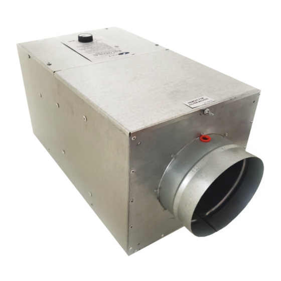
FRESH AIR POWER VENTILATOR
ITEMS INCLUDED:
• FAPV inline fan unit
• MERV-6 washable fi lter
• Mounting Brackets (2)
• #10 sheet metal screws, blunt point (4)
• Instruction Booklet
WARNING:
WARNING: READ AND SAVE THESE INSTRUCTIONS. Read these instructions carefully and entirely before
READ AND SAVE THESE INSTRUCTIONS. Read these instructions carefully and entirely before
attempting to assemble, install, operate, or maintain this product and related equipment. Protect yourself
attempting to assemble, install, operate, or maintain this product and related equipment. Protect yourself
and others by observing all safety cautions, warnings and information. Failure to comply with instructions
and others by observing all safety cautions, warnings and information. Failure to comply with instructions
could result in personal injury and/or property damage.
could result in personal injury and/or property damage.
The FAPV Power Ventilator is an inline duct-connected fan intended for use to provide fresh outdoor air for the
purpose of meeting indoor ventilation code requirements and occupant preferences. Fresh outdoor air is brought
in through an outdoor intake air hood and ducted into the ventilator, which discharges the fresh air either by
duct connection to HVAC ductwork (see further instructions), or directly into the space to be ventilated, such as a
mechanical closet.
WARNING: Do not use the FAPV ventilator as an exhaust fan for range hoods, combustion appliances or
WARNING:
Do not use the FAPV ventilator as an exhaust fan for range hoods, combustion appliances or
equipment, damp locations such as spaces with bathtubs, pools or showers, or hazardous or explosive
equipment, damp locations such as spaces with bathtubs, pools or showers, or hazardous or explosive
gases or vapors.
gases or vapors.
WARNING: 115 VOLTS MAY CAUSE SEROIUS INJURY OR DEATH FROM ELECTRICAL SHOCK. DISCONNECT AND
WARNING:
115 VOLTS MAY CAUSE SEROIUS INJURY OR DEATH FROM ELECTRICAL SHOCK. DISCONNECT AND
TAG ELECTRICAL SERVICE BEFOR STARTING INSTALLATION OR FIELD SERVICE. LEAVE ELECTRICAL SERVICE
TAG ELECTRICAL SERVICE BEFOR STARTING INSTALLATION OR FIELD SERVICE. LEAVE ELECTRICAL SERVICE
DISCONNEDTED UNTIL INSTALLATION OR FIELD SERVICE IS COMPLETE.
DISCONNEDTED UNTIL INSTALLATION OR FIELD SERVICE IS COMPLETE.
This device MUST be installed by a qualifi ed agency in accordance with the manufacturer's installation instructions. The defi nition of
a qualifi ed agency is: any individual, fi rm, corporation or company which either in person or through a representative is engaged
in, and is responsible for, the installation and operation of HVAC appliances, who is experienced in such work, familiar with all the
precautions required, and has complied with all the requirements of the authority having jurisdiction.
Installed By:
Model: FAPV180-AC
Please retain these instructions after installation.
Phone:
www.fi eldcontrols.com
Installation Date:
P/N 780104900 Rev A 09/20
Advertisement
Table of Contents

Related Manuals for Field Controls FAPV180-AC


Summary of Contents for Field Controls FAPV180-AC
- Page 1 FRESH AIR POWER VENTILATOR Model: FAPV180-AC ITEMS INCLUDED: • FAPV inline fan unit • MERV-6 washable fi lter • Mounting Brackets (2) • #10 sheet metal screws, blunt point (4) • Instruction Booklet WARNING: WARNING: READ AND SAVE THESE INSTRUCTIONS. Read these instructions carefully and entirely before READ AND SAVE THESE INSTRUCTIONS.
- Page 2 (THIS PAGE LEFT INTENTIONALLY BLANK) P/N 780104900 Rev A 09/20 page 2 of 20...
-
Page 3: Specifications
SPECIFICATIONS PSC Motor Class F Insulated Thermally protected Motorized Impeller Specifi cations UL, CSA recognized Impeller rated UL 94-5VA fl ammability Sealed ball bearings Nominal RPM: 2600 Power Supply 115 VAC, 60 Hz Watts (mx speed) Amps (max speed) 0.90A Temperature Range -22 to 140°F Ambient Outdoor Temperature Control Voltage (optional) -
Page 4: Planning For Installation
The air intake hood or termination must have an insect screen of maximum ¼” mesh size. The Field Controls model IAH-6 meets this specifi cation. - Page 5 If the outlet duct is to be connected to the return ducting of the HVAC system and the FAPV is set up for intermittent ventilation, installation of a 24 VAC powered air damper such as the Field Controls model FAD-6 is strongly recommended to prevent incoming air fl ow during periods when the HVAC fan is active but the FAPV is not active.
-
Page 6: Ductwork Installation
NOTE: if a ventilation controller having an outdoor air temperature sensor that may be mounted on the inlet air duct is to be used (such as Field Controls model FAVC), follow the manufacturer’s instructions to mount the outdoor temperature sensor on the inlet air duct, as close to the intake air hood as is reasonably convenient, see Figures 4 and 5. - Page 7 Inspect the factory-installed backdraft damper vanes and their seal in the outlet collar of the FAPV fan unit and verify proper operation of the damper. Air fl ow through the FAPV will cause the damper vanes to open; spring pressure/air pressure will cause the vanes to close when air fl ow ceases or tends to go back out of the FAPV towards the inlet air hood.
- Page 8 TABLE A: MIXED AIR PLENUM TEMPERATURE P/N 780104900 Rev A 09/20 page 8 of 20...
- Page 9 The FAPV Power Ventilator may be set up to operate continuously with a 115 VAC power source alone, or to operate intermittently as controlled by a ventilation controller having 24VAC output, such as the Field Controls model FAVC Ventilation Control.
- Page 10 For Intermittent Operation as Controlled by a 24 VAC-output Ventilation Controller For Intermittent Operation as Controlled by a 24 VAC-output Ventilation Controller (Field Controls model FAVC recommended, sold separately): (Field Controls model FAVC recommended, sold separately): Wiring Diagram B: INTERMITTENT OPERATION Complete steps 1 through 6 as given in the section for continuous standalone operation.
- Page 11 T1 and T2 during a call for ventilation by the controller. If unsure about control wiring connections, contact Field Controls Technical Support for assistance. If unsure about control wiring connections, contact Field Controls Technical Support for assistance.
- Page 12 • • Pitot Tube Measurement using a Manometer with fl ow measurement capability (HVAC air pressure/fl ow Pitot Tube Measurement using a Manometer with fl ow measurement capability (HVAC air pressure/fl ow measurement instrument), see Figure 6: measurement instrument), see Figure 6: Turn on the manometer and perform the “zero”...
- Page 13 Adjust the speed control knob on the FAPV until this static pressure is measured. NOTE: the static pressure more closely matching the actual desired fl owrate may be “interpolated” from adjacent column cfm values if desired. Contact Field Controls Technical Support for assistance if needed for help with interpolation.
- Page 14 Inlet Duct Pressure Drop Flow Rate tables: P/N 780104900 Rev A 09/20 page 14 of 20...
- Page 15 AIR FLOWRATE ADJUSTMENT PROCEDURE Restore power and turn on the electrical disconnect switch if installed. If the FAPV ventilator outlet is connected to the HVAC ductwork, set the indoor thermostat to a setting resulting in operation of the HVAC circulation fan. Adjust the FAPV fan unit speed control knob to the Max setting (fully counterclockwise without turning to OFF position).
- Page 16 Cleaning the prefi lter and installing or replacing a 10 x 10 x 2” air fi lter in the FAPV:: Cleaning the prefi lter and installing or replacing a 10 x 10 x 2” air fi lter in the FAPV:: Switch off the electrical disconnect switch supplying power to the FAPV fan unit.
-
Page 17: Troubleshooting
Some controllers may allow suffi cient electronic “bleed voltage” to cause the FAPV to run when there is no intended call for heat. Use a dry-contact type ventilation controller if necessary, such as Field Controls models HHSC, HHSC+ or FAVC. Check ventilation controller for proper 24V ventilation output confi guration. - Page 18 (THIS PAGE LEFT INTENTIONALLY BLANK) page 18 of 20 P/N 780104900 Rev A 09/20...
-
Page 19: Replacement Parts
REPLACEMENT PARTS Description Description Model Number Model Number Part Number Part Number Prefi lter, FAPV Prefi lter FAPV 800108700 Motorized Impeller Motorized Fan CAS-3,4 46274100 Electronic Speed Control Control Mod KBWC-14 Mtr Apd 04312200 24 VAC Relay Relay 24V DPDT Surface Mount 46161400 8 microfarad Motor Capacitor Capacitor CAS-3,4... - Page 20 This manual may be downloaded and printed from the Field Controls website (www.fi eldcontrols.com) This manual may be downloaded and printed from the Field Controls website (www.fi eldcontrols.com) WARRANTY WARRANTY For warranty information about this or any Field Controls product, visit: For warranty information about this or any Field Controls product, visit: www.fi eldcontrols.com...
Need help?
Do you have a question about the FAPV180-AC and is the answer not in the manual?
Questions and answers