Table of Contents
Advertisement
Advertisement
Table of Contents

Related Manuals for Cushman HAULER PRO 2022


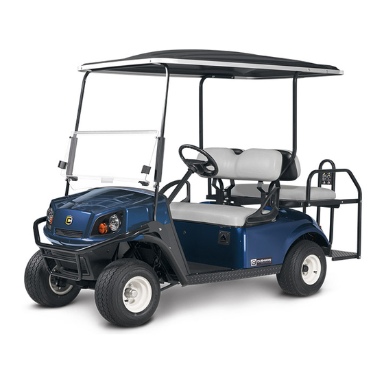
Summary of Contents for Cushman HAULER PRO 2022
- Page 1 OWNER’S MANUAL HAULER PRO 10002108-A...
- Page 2 Read and comply with all of the instructions and safety precautions in this manual and on all product labels. Failure to follow the safety precautions could result in serious injury or death. California Proposition 65 WARNING Operating, servicing and maintaining a passenger vehicle or off-road vehicle can expose you to chemicals including phthalates and lead, which are known to the State of California to cause cancer and birth defects or other reproductive harm.
- Page 3 OWNER’S GUIDE HAULER PRO MODEL YEAR 2022 CONTACT INFORMATION Textron Specialized Vehicles, Inc. 1451 Marvin Griffin Road. Augusta, Georgia, USA 30906-3852 North America: Technical Assistance & Warranty PHONE: 1-800-774-3946, FAX: 1-800-448-8124 Service Parts PHONE: 1-800-438-3946, FAX: 1-800-752-6175 International PHONE: 001-706-798-4311, FAX: 001-706-771-4609 cushmancomm@textron.com...
- Page 4 ELCOME Thank you for purchasing this vehicle. Before driving your new vehicle, read this owner’s manual to familiarize your- self with safe driving practices, operation, features and controls. This manual contains instructions for minor maintenance only. Information about major repairs can be found in the repair manual.
-
Page 5: Table Of Contents
ABLE OF ONTENTS INTRODUCTION MANUFACTURER’S INTENDED USE ........................7 WARRANTY AND REGISTRATION .........................7 BATTERY PROLONGED STORAGE ........................7 BATTERY PROLONGED STORAGE ........................8 Storage Preparation ............................8 Setting State of Charge (SOC) .......................... 8 During Storage ..............................8 Extreme Low Temperature Storage ........................8 Returning Vehicle to Service ..........................8 BATTERY DISPOSAL ............................... - Page 6 ABLE OF ONTENTS FEATURES AND CONTROLS KEY SWITCH ................................21 HEADLIGHT SWITCH ............................. 21 ELECTRIC BED LIFT SWITCH (IF EQUIPPED) ....................21 STATE OF CHARGE METER ..........................21 HORN ..................................21 CUP HOLDER .................................21 12V OUTLET (IF EQUIPPED) ..........................21 USB PORT (IF EQUIPPED) ............................21 HOUR METER (IF EQUIPPED) ..........................22 STEERING WHEEL ..............................22 TURN SIGNAL (IF EQUIPPED) ..........................22...
- Page 7 ABLE OF ONTENTS Coasting ................................29 DRIVING WITH A PASSENGER ..........................29 SLIPPERY SURFACES ............................30 DRIVING UPHILL ..............................30 TRAVERSING HILLSIDES ............................30 DRIVING DOWNHILL ............................. 30 STALLING ON A HILL ............................. 31 DRIVING IN REVERSE ............................31 PARKING THE VEHICLE ............................31 HAULING CARGO ..............................
- Page 8 ABLE OF ONTENTS FUSE REPLACEMENT ............................48 CONTROLLER SYSTEM TEST ..........................48 REAR AXLE ................................48 Checking the Lubricant Level .......................... 48 LUBRICATION ................................ 48 BRAKES ..................................49 Periodic Brake Test ............................49 LITHIUM-ION BATTERY PACK ..........................50 BATTERY CHARGING AND MAINTENANCE ......................50 BATTERY CHARGING ............................51 BATTERY PROLONGED STORAGE ........................51 Storage Preparation ............................51 BATTERY FAULT DIAGNOSIS ..........................51...
-
Page 9: Manufacturer's Intended Use
Check all laws and regulations before choosing an area to operate your vehicle. WARRANTY AND REGISTRATION Go to www.cushman.com for vehicle registration. For vehicle warranty transfer, change of address or vehicle ownership, use the form at the end of this owner’s manual. -
Page 10: Battery Prolonged Storage
NTRODUCTION BATTERY PROLONGED STORAGE NOTICE: Improper storage may damage, destroy or cause permanent loss of battery capacity. Do not exceed storage time or temperature limits. Batteries must be charged to the correct level before storage. Storing fully depleted batteries will make them permanently unusable. Storage Preparation The optimum storage temperature range is between 65°F and 82°F (18°C and 28°C) •... -
Page 11: Battery Disposal
AFETY BATTERY DISPOSAL Lithium-Ion batteries are recyclable: •Contact the distributor or manufacturer for information on returning or recycling used or damaged battery packs. •Contact local or state environmental department for disposal information. •Refer to the Maintenance section for additional information. VEHICLE IDENTIFICATION NUMBERS PART A PART B... - Page 12 NTRODUCTION...
-
Page 13: Safety Labels
AFETY SAFETY For questions about your vehicle or the material in this manual, see the contact information on page 1 or the back of this publication. Certain replacement parts can be used independently and/or in combination with other accessories to modify a TSV (Augusta) manufactured vehicle to permit the vehicle to operate at or in excess of 20 mph. -
Page 14: Operation (P/N 664789) (If Equipped With Card Holder)
AFETY Operation (P/N 664789) (If equipped with card holder) Located on the steering wheel. READ AND OBEY THE FOLLOWING WARNINGS TO DECREASE RISK OF SEVERE INJURY OR DEATH. 664789 Pressing the accelerator pedal releases the parking brake even when the key is in the OFF position; the vehicle may move when the accelerator pedal is pressed. -
Page 15: Load Bed (P/N 74821G03)
AFETY Load Bed (P/N 74821G03) Located on the truck bed. HIGH CENTER WARNING SECURE LOAD PASSENGERS OF GRAVITY MAY READ THE MANUAL MAX BED WEIGHT IN LOAD BED CAUSE TIP OVER 800 lb. 360 kg 5 in. 12 cm / 25% 100 lb. -
Page 16: Load Bed (P/N 35980G04)
AFETY Load Bed (P/N 35980G04) HIGH CENTER WARNING SECURE LOAD PASSENGERS OF GRAVITY MAY READ THE MANUAL MAX BED WEIGHT IN LOAD BED CAUSE TIP OVER 800 lb. 363 kg 5 in. 12 cm / 25% 35980G04 DO NOT FILL GAS MAX CENTER OF MAX SIDE CAN IN LOAD BED... -
Page 17: Run/Tow Switch Operation (P/N 633950)
AFETY Run/Tow Switch Operation (P/N 633950) Located on the run/tow switch. 633950 MAXIMUM CARGO LOAD / MAXIMUM WEIGHT CAPACITY Exceeding the weight capacities can cause loss of vehicle control and possible injury or death. Maximum Cargo Load Capacity 800 lbs. (360 kg) Maximum Vehicle Weight Capacity 1200 lbs. -
Page 18: Unauthorized Operation
AFETY • Inspect the vehicle before each use to make sure it is in safe operating condition. Perform the pre-ride inspection described in this manual. See page 25. • Always have the vehicle checked by an authorized dealer if it is involved in an accident. •... -
Page 19: Before Operating
AFETY Before Operating Perform the PRE-RIDE INSPECTION on page 25 before each use to make sure the vehicle is in safe operating con- dition. Failure to inspect and confirm that the vehicle is safe to operate increases the risk of an accident. Follow all inspection and maintenance procedures and schedules described in this owner’s manual. -
Page 20: Stalling On A Hill
AFETY Stalling on a Hill A rollover can result from stalling or rolling backward while climbing a hill. Drive uphill at a constant speed. See proce- dure on page 31 for maintaining control of your vehicle if it stalls on a hill. Tires Operating the vehicle with incorrect tires or with incorrect or uneven tire pressure can cause loss of control or an acci- dent. -
Page 21: Maintenance Safety
AFETY MAINTENANCE SAFETY Routine and scheduled maintenance of this vehicle is necessary to keep your vehicle in safe and reliable condition. This section of the manual provides safety information for performing maintenance on your vehicle. Make sure you read, understand and comply with all of this information to decrease the risk of personal injury or death. Serious injury or death can occur if you do not follow the instructions and procedures shown in this owner’s manual. - Page 22 AFETY...
-
Page 23: Features And Controls
EATURES AND ONTROLS FEATURES AND CONTROLS NOTICE: Some accessories continue to operate with the key in the OFF position. Leaving these accessories activated after the vehicle is shut down can cause the battery to discharge. 12V accessories must be connected to the DC to DC converter. Converter is rated for 390 Watt out- put. -
Page 24: Hour Meter (If Equipped)
EATURES AND ONTROLS HOUR METER (If Equipped) The hour meter is located under the driver’s seat and indicates the vehicle’s total hours of operation. STEERING WHEEL Steering Wheel The steering wheel allows the driver to control the Turn Signal Switch direction of travel. -
Page 25: Accelerator Pedal
EATURES AND ONTROLS ACCELERATOR PEDAL The accelerator pedal is the right pedal on the floorboard. It activates the engine and controls the acceleration of the vehicle. Apply slow and steady pressure to the accelerator pedal to increase vehicle speed. DIRECTION SELECTOR Direction The direction selector is the key switch. -
Page 26: Canopy Top And Windshield
EATURES AND ONTROLS Rear passengers must stay in the seat and hold both hip restraints and the rear hand hold when the vehicle is in motion. Always make sure that all passengers are seated and holding on before operating the vehicle. Do not allow passengers to ride on the load deck. -
Page 27: Operation
PERATION OPERATION SAFETY Failure to operate the vehicle correctly can result in a collision, loss of control, accident or rollover, and cause serious injury or death. Follow all operation procedures in this section of the manual. Read and comply with all safety warnings in the safety section of this owner’s manual. -
Page 28: Environmental Awareness
PERATION ENVIRONMENTAL AWARENESS When driving the vehicle, be careful of potential environmental hazards like steep slopes, rocks, tree branches, etc. that could cause an incident that could result in vehicle damage, personal injury or death. There is a risk of fire when the vehicle is operated near combustible material. Always be respectful of the environment. -
Page 29: Performance Features
PERATION PERFORMANCE FEATURES NOTICE: The vehicle operates when the Run/Tow switch is in the RUN position. The speed of the motor is sensed and controlled by the controller. Speed Control The speed control system is not an alternative for the brake. Use the brake to control speed and decrease the risk of injury. -
Page 30: High Pedal Disable Feature
PERATION the Anti-Stall feature senses a stalled motor condition and removes power from the motor. When the brake pedal is released, the vehicle will move backward slightly before power is returned to the motor. High Pedal Disable Feature High Pedal Disable prevents acceleration of the vehicle if the direction selector is changed or the key is turned on while the accelerator is pressed. -
Page 31: Braking
PERATION Apply slow, steady pressure to the accelerator pedal to increase vehicle speed. When you release the accelera- tor pedal, the motor decreases the speed of the vehicle. NOTICE: On mechanical brake vehicles, if the key switch is in the ON position and the parking brake is engaged, the brake releases when you press the accelerator pedal and can cause the vehicle to move suddenly. -
Page 32: Slippery Surfaces
PERATION • Handling characteristics can change with the added weight of a passenger. Allow more time and distance for brak- ing. SLIPPERY SURFACES Skidding or sliding can cause loss of control. Skidding or sliding can cause rollover if tires have lost traction, then regain traction suddenly. When operating on slippery sur- faces, travel at reduced speed to help maintain control of the vehicle. -
Page 33: Stalling On A Hill
PERATION • Never drive down hills with excessively slippery or loose surfaces. • Drive slowly. • Drive straight down the hill. Avoid descending the hill at an angle that could cause the vehicle to lean sharply to one side. • Apply light and constant pressure to the brakes to maintain slow speed and control of the vehicle. STALLING ON A HILL A rollover can result from stalling or rolling backward while climbing a hill. -
Page 34: Hauling Cargo
PERATION HAULING CARGO Hauling cargo incorrectly can alter vehicle handling characteristics and cause loss of control, brake instability, and possibly lead to serious injury or death. Never exceed the maximum weight capacity of the vehicle. The total load (operator, pas- senger, accessories, cargo and load on hitch) must never exceed the maximum weight capacity of the vehicle. -
Page 35: Flip Seat/ Load Deck Operation (If Equipped)
PERATION Flip Seat/ Load Deck Operation (If Equipped) To reduce the possibility of severe injury or death never operate vehicle without the rear handhold installed in the proper position. When rear seat is used the handhold must be positioned in the setting closest to the footrest and secured with the hand knob. Some vehicles are equipped with a rear facing seat that pivots to form a load deck. -
Page 36: Truck Bed Operation
PERATION TRUCK BED OPERATION Failure to follow these instructions can cause personal injury, damage the vehicle or cause the vehicle to tip over. Be aware of the load when you operate the vehicle. Read, understand and follow the warning label attached to the front of the truck bed. Do not allow passengers to ride in the truck bed. -
Page 37: Towing
PERATION Put the direction selector in forward (F). Exit the vehicle. Make sure the cargo is positioned evenly or located at the front of the truck bed. Release the tailgate latches. Manual bed lift vehicles: Stand clear and pull the release handle. Lift up on the truck bed to dump the cargo. - Page 38 PERATION...
-
Page 39: Winch
INCH WINCH The safety warnings and information in this section apply if your vehicle has a winch. Improper or irresponsible use of the winch can result in severe injury or death. Always follow all winch instructions and warnings in this manual. WINCH SAFETY •... -
Page 40: Winch Operation
INCH WINCH OPERATION Read all of the Winch Safety beginning page 37 before operating your winch. NOTICE: Practicing operation and use of the winch before it is needed to perform a job is recommended. Improper or irresponsible winch use can result in severe injury or death. Comply with all winch instructions and warnings in this manual. -
Page 41: Winch Cable Care
INCH Pull out as much cable as possible to maximize the winch’s pulling capac- ity. Maintain at least five full turns of winch cable wrapped around the winch drum at all times. The friction provided by the wrapped cable allows Minimum five (5) the drum to pull on the winch cable and move the load. -
Page 42: Shock Loading
INCH • Always inspect the winch cable before each use. Inspect for wear or kinks in the cable. – A kinked winch cable made of wire rope is shown at right. Even after being straightened out, this cable has been permanently and severely damaged. -
Page 43: Maintenance
AINTENANCE MAINTENANCE MAINTENANCE SAFETY To prevent serious injury or death, follow the procedures and comply with the safety information in this manual while performing vehicle service or maintenance. Use the tools shown in the tool list and wear the specified safety equipment when per- forming vehicle service or maintenance. -
Page 44: Scheduled Maintenance Chart
AINTENANCE SCHEDULED MAINTENANCE CHART Perform all services at the maintenance interval reached first. S – Indicates operations that need to be performed on vehicles subjected to severe use. Interval (perform at interval Item Remarks Page that comes first) Hours Calendar Overall vehicle condition Pre-ride Inspect. -
Page 45: Recommended Lubricants And Fluids
AINTENANCE RECOMMENDED LUBRICANTS AND FLUIDS Check and lubricate all components at the intervals shown in the SCHEDULED MAINTENANCE CHART beginning on page 42. Item Capacity Lubricants/Fluids Notes Rear axle oil 25 oz. (0.7 L) Mobil 424 Part Number 603967 Rear axle oil 2.0 oz (59 mL) Friction Modifier E-Z-GO Part Number 611242... -
Page 46: Lifting The Vehicle
AINTENANCE LIFTING THE VEHICLE Read and comply with all of the following warnings and lifting procedures to prevent the possibility of the vehicle falling and causing serious injury or death. For some maintenance procedures, it is necessary to lift the vehicle. Comply with the following warnings and follow the lifting procedure to ensure the safety of you, your vehicle and surroundings. -
Page 47: Vehicle Cleaning And Care
AINTENANCE VEHICLE CLEANING AND CARE Keeping your vehicle clean is not only beneficial to its appearance, but can also help extend the life of various compo- nents. Washing the Vehicle NOTICE: Do not use a pressure washer to wash your vehicle. High water pressure can damage components. Some products, including insect repellents and chemicals, will damage plastic surfaces. -
Page 48: Tire Pressure
AINTENANCE Tire Pressure Maintaining correct tire inflation pressure is essential for safe vehicle operation. You can vary the inflation pressure, within the recommended range to suit the condition of the terrain. TIRE PRESSURE RANGE TERRAIN CONDITIONS RECOMMENDATION Inflate to higher pressure within the range; never exceed hard surfaces or pavement maximum pressure indicated. -
Page 49: Wheel Installation
AINTENANCE Wheel Installation Lug Nut Torque 65 - 85 ft.lbs. (88 - 115 Nm) NOTICE: To decrease the risk of component damage, do not tighten the lug nuts Lug Nut Tightening Pattern to more than the specified torque. Always install lug nuts using a cross sequence pattern to ensure even seating of the wheel against the hub. -
Page 50: Fuse Replacement
AINTENANCE FUSE REPLACEMENT 58V, 10A Mini Fuse NOTICE: Have the vehicle inspected by your dealer if fuses continue to blow after 12V, 20A Relay 32V, 10A Mini Fuse they have been replaced. Lift the seat bottom to access the PDM. Open the PDM to access the fuses. -
Page 51: Brakes
AINTENANCE BRAKES Always inspect the pedal travel before you operate a vehicle to confirm some brake func- tion is present. All driving brake tests must be done in a safe location with regard for the safety of all personnel. NOTICE: Over time, a subtle loss of performance may take place; therefore, it is important to establish the standard with a new vehicle. -
Page 52: Lithium-Ion Battery Pack
AINTENANCE LITHIUM-ION BATTERY PACK Charge the battery pack using only the OEM approved Lithium-Ion battery charger. Improper handling of batteries and electrical components can result in serious injury or death. Do not remove the battery pack cover. Do not attempt to remove batteries or battery cables. -
Page 53: Battery Charging
AINTENANCE BATTERY CHARGING The battery charger is designed to completely charge the battery set. The automatic charger determines the correct length of charge for the battery set and turns off when the batteries are charged. Always refer to the instructions sup- plied with the charger. -
Page 54: Transporting The Vehicle
AINTENANCE TRANSPORTING THE VEHICLE Do not ride or allow other people on a vehicle being transported on a trailer or being towed with another vehicle. Towing the Vehicle Do not try to tow the vehicle with ropes, chains or any device. This vehicle is not designed to be towed. -
Page 55: Specifications
PECIFICATIONS SPECIFICATIONS VEHICLE SPECIFICATIONS • Solid State continuously variable AC speed • Full torque, reduced speed reverse controller • Key Switch direction selector • Inductive throttle sensor (Forward-Neutral-Reverse) • Anti-roll back, walkaway braking and alarm • Diagnostic indicator • Anti-stall motor protection •... - Page 56 PECIFICATIONS Vehicle Load Capacity 1200 lb. (360 kg) Outside Clearance Circle 21.5 ft. (6.6 m) Speed (Level Ground) 16.5 mph ± 0.5 mph (26.35 kph ± 0.8 kph) Towing Capacity 1500 lbs (544 kg) max load Steering Self-compensating rack and pinion Front Suspension Leaf springs with hydraulic shock absorbers Rear Suspension...
- Page 57 AINTENANCE MAINTENANCE LOG Record periodic maintenance in the following maintenance log. MILES (KM) SERVICE PERFORMED DATE TECHNICIAN AND HOURS COMMENTS...
- Page 58 AINTENANCE MILES (KM) SERVICE PERFORMED DATE TECHNICIAN AND HOURS COMMENTS...
- Page 59 AINTENANCE MILES (KM) SERVICE PERFORMED DATE TECHNICIAN AND HOURS COMMENTS...
- Page 60 AINTENANCE MILES (KM) SERVICE PERFORMED DATE TECHNICIAN AND HOURS COMMENTS...
- Page 61 PPENDIX APPENDIX A BATTERY CHARGER USER’S GUIDE...
- Page 62 PPENDIX 1 kW Industrial Battery Charger QuiQ Charger - E-Z-GO Product Manual This manual contains important safety and operating instructions for versions of the Delta-Q QuiQ (Model nos. 913-4830-E3/- E3B/-E5 /-E5B) installed on E-Z-GO brand vehicles. Please read this information before using your QuiQ Charger. For manufacturer contact information and technical support resources, please visit delta-q.com/support SAVE THESE IMPORTANT SAFETY INSTRUCTIONS - This manual contains...
- Page 63 PPENDIX Delta-Q QuiQ Charger Manual Operating Instructions CAUTION: Charger enclosure may be hot during charging. Use hand protection if handling the charger while charging. Extension cords must be 3-wire cord no longer than 30m(100’) at 10AWG or 7.5m(25’) at 16AWG per UL guidelines. Only connect ONE QuiQ charger to a single 15A circuit or the circuit may become overloaded.
- Page 64 PPENDIX...
- Page 65 PPENDIX APPENDIX B BATTERY CHARGER USER’S GUIDE...
- Page 66 PPENDIX Manuel d’origine de l’utilisateur RC900 ELiTE Onboard Charger du Chargeur À bord RC900 ELiTE Original User Manual Le présent manuel contient d’importantes This manual contains important safety and consignes de sécurité et d’utilisation pour cette operating instructions for this version of the version du chargeur Delta-Q à...
- Page 67 PPENDIX Operating & Maintenance Instructions ™ The charger may become hot during charging. Do not touch the charger when it is charging. ™ To maintain safe operations, the unit automatically reduces its output power if the temperature rises above set thresholds, or if the AC input voltage is too low. The charger also reduces output power if it detects the battery pack is damaged.
- Page 68 PPENDIX...
- Page 69 PPENDIX APPENDIX C BATTERY CHARGER USER’S GUIDE...
- Page 70 PPENDIX Lithium Golf Cart Chargeur de batterie au lithium Battery Charger pour chariot de golf Manuel d’origine de l’utilisateur E-Z-GO ELiTE Charger du Chargeur E-Z-GO ELiTE Original User Manual Le présent manuel contient d’importantes consignes de sécurité et This manual contains important safety and operating instructions for d’utilisation pour ces versions du Chargeur Delta-Q ELiTE (numéros de these versions of the Delta-Q ELiTE Charger (Part Nos.
- Page 71 PPENDIX Consignes d’entretien Maintenance Instructions Le boîtier en tout modèles de chargeur est conforme à la The enclosure on all charger models meets IP56, making it norme IP56, le protégeant ainsi contre l’infiltration de protected from dust ingress and powerful water jets. The AC poussière et les jets d’eau puissants.
- Page 72 PPENDIX Operating Instructions CAUTION: The charger enclosure may be hot during charging. Use hand protection if handling the charger while charging. The extension cord must be a 3-wire cord less than 30m (100’) at 10AWG or 7.5m (25’) at 16AWG per UL guidelines. If you are connecting four (4) ELiTE Chargers to a single 120V mains circuit, a 20A circuit is recommended.
- Page 73 PPENDIX Mode d’emploi MISE EN GARDE : Le boîtier du chargeur peut devenir chaud pendant le chargement. Utilisez une protection pour les mains si vous manipulez le chargeur pendant le chargement. La rallonge électrique doit être un cordon à 3 fils de moins de 30 m (100 pi) de long à 10 AWG ou 7,5 m (25 pi) à 16 AWG selon les directives UL. Si vous connectez quatre (4) chargeurs ELiTE à...
- Page 74 PPENDIX Troubleshooting Instructions If a fault occurs, count the number of red flashes between pauses and refer to this table: Flashes Cause Solution The lithium battery pack issued Check the green DC paddle and receptacle for damage, corrosion, and a fault indicating a wiring or ensure it is properly inserted.
- Page 75 NDEX INDEX auxiliary outlet, 12V 21 hauling, vehicle 52 headlights 47 hitch weight capacity 35 battery horn switch 21 prolonged storage 8 battery charger 26 battery disposal 9 key switch 21 battery maintenance 50 bed lift switch, electric 21 labels, safety 11 brakes 49 lifting, vehicle 18, 44 pedal, mechanical 22...
- Page 76 NDEX vehicle modification 18 safety 37 weight capacity 15, 32 shock loading 40 winch 37 safety symbols 7 scheduled maintenance chart 42 seat bottom 23 serial number labels 9 shock loading, winch 40 slippery surfaces 30 specifications, vehicle 53 steering wheel 22 storage compartments 23 switches bed lift, electric 21...
- Page 77 CHANGE OF ADDRESS, OWNERSHIP, OR WARRANTY TRANSFER Textron Specialized Vehicles keeps on file the current name and address of the owner of this vehicle. This allows us to contact the current owner with any import- ant safety information which may be necessary to protect customers from personal injury or property damage.
- Page 78 FOLD Place Stamp CHANGE OF ADDRESS/OWNERSHIP OR WARRANTY TRANSFER Here TEXTRON SPECIALIZED VEHICLES 1451 MARVIN GRIFFIN RD AUGUSTA GA 30906-3852 ATTN: WARRANTY DEPARTMENT...
- Page 79 Normal use, age and wear on vehicle components can affect the safe operation and reliability of the vehicle. The rec- ommended Inspection and maintenance procedures are crucial for safety, performance, reliability and maximum lon- gevity of your vehicle. A damaged vehicle, or a vehicle that is not functioning properly is dangerous and must not be operated until repairs are made.
- Page 80 TEXTRON SPECIALIZED VEHICLES, INC. 1451 Marvin Griffin Road Augusta, Georgia 30906 - 3852 CONTACT INFORMATION North America: Technical Assistance & Warranty: Phone: 1-800-774-3946, FAX: 1-800-448-8124 Service Parts Phone: 1-888-GET-E-Z-GO (1-888-438-3946), FAX: 1-800-752-6175 International: Phone: 001-706-798-4311, FAX: 001-706-771-4609 California Proposition 65 WARNING Operating, servicing and maintaining a passenger vehicle or off-road vehicle can expose you to chemicals including phthalates and lead, which are known to...
Need help?
Do you have a question about the HAULER PRO 2022 and is the answer not in the manual?
Questions and answers