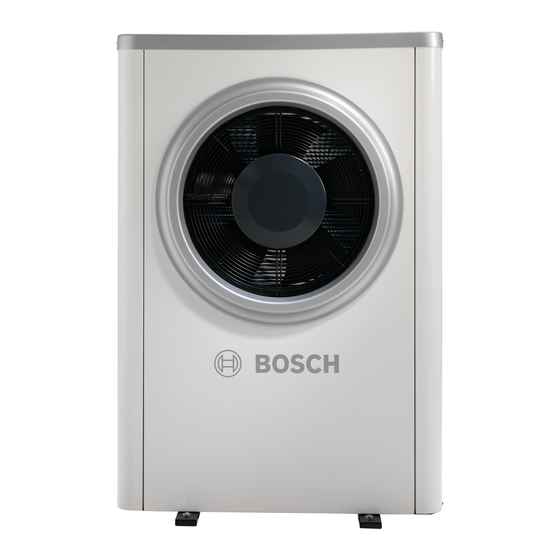
Bosch Compress 7000i AW Installation Manual

Bosch Compress 7000i AW Installation Manual

Air to water heat pump
Hide thumbs Also See for Compress 7000i AW:

Advertisement

Installation Manual
Air to Water Heat Pump
Compress 7000i AW
5-17 OR-S/T

Advertisement

Table of Contents
loading

Summary of Contents for Bosch Compress 7000i AW

  • Page 1 Installation Manual Air to Water Heat Pump Compress 7000i AW 5-17 OR-S/T...
  • Page 2: Table Of Contents

    / three-phase current ....27 9.5.2 Wiring diagram for I/O module card ....28 Compress 7000i AW – 6721830633 (2021/02)
  • Page 3: Explanation Of Symbols And Safety Instructions

    H Intended operation This heat pump is intended to be used in a closed heating system for households. All other use is considered unsuitable. Any damage that is caused by such usage is excluded from liability. Compress 7000i AW – 6721830633 (2021/02)
  • Page 4: Regulations

    This means that the heating system will be more sensitive to rust with Table 2 Water quality in the heating system aggressive water. Product description Supplied parts Fig. 1 Supplied parts Heat pump Adjustable feet Cover and side panels Compress 7000i AW – 6721830633 (2021/02)
  • Page 5: Heat Pump Details

    Product description Heat pump details Product overview The Compress 7000i AW heat pumps are intended for connection to the AWM/AWMS or AWE/AWB indoor units. Possible combinations: AWM / AWMS AWE / AWB Compress 7000i AW 5 OR-S 7 OR-S 9 OR-S...
  • Page 6: Dimensions

    Dimensions and connections of heat pump models 5 OR-S-9 OR-S 1122 ø10,5 ø10,5 Fig. 6 Dimensions of heat pump models 13 OR-S/T-17 OR-T, view from top Fig. 4 Dimensions of heat pump models 5 OR-S-9 OR-S, view from top Compress 7000i AW – 6721830633 (2021/02)
  • Page 7: Clearances During Setup

    Fig. 8 Avoid setting up in locations surrounded by walls ▶ Whenever possible, do not set up the heat pump in front of rooms sensitive to noise. Compress 7000i AW – 6721830633 (2021/02)
  • Page 8: For Drainage

    Condensate tube 32 mm Gravel bed Fig. 10 Danger! Ice formation in front of heat pumps with noise- attenuating device (accessory) Area in front of the heat pump with noise-attenuating device (accessory) in which ice can form. Compress 7000i AW – 6721830633 (2021/02)
  • Page 9: Minimum Volume And Execution Of The Heating System

    • Required volume for heat pump 13 OR-S/T – 17 OR-T = ≥ 100 litres. Only fan convectors To prevent the auxiliary heater from being activated in the final phase of the defrosting process, a buffer storage tank with a capacity of ≥ 10 l is required. Compress 7000i AW – 6721830633 (2021/02)
  • Page 10: Unpacking

    Adjustable feet hose which is suitable for use outdoors and also insulate it. 4 pieces M10 X120 mm (not included in scope of delivery) Level subsurface with sufficient load bearing capacity, e.g. concrete foundations Compress 7000i AW – 6721830633 (2021/02)
  • Page 11 2) The installation of a 3-way valve in the DHW circuit of the system was factored into the calculation of the pipe lengths. Table 5 Pipe dimensions and maximum pipe lengths (single section) when connecting the heat pump to the AWB indoor unit with mixer for the external auxiliary heater Compress 7000i AW – 6721830633 (2021/02)
  • Page 12: Water Connecting Pipe

    Fig. 16 Condensate tube connections, valid for all sizes Condensate line in rainwater gully Condensate line in gravel bed/stone box Connection for condensate tube Compress 7000i AW – 6721830633 (2021/02)
  • Page 13: Electrical Connection

    ▶ Check to ensure that the cables are connected to the contacts with the corresponding markings on the circuit board. The heat pump and indoor unit are connected to each other by a communication line, the CAN-BUS. Compress 7000i AW – 6721830633 (2021/02)
  • Page 14 Installation Fig. 19 Cable conduits and control device Cable conduit, power supply Cable conduit CAN-BUS 3-phase heat pump 1-phase heat pump Connection CAN-BUS Compress 7000i AW – 6721830633 (2021/02)
  • Page 15: Installing Side Panels And Cover

    Installation Installing side panels and cover 0010020097-002 Fig. 20 Installing side panels and cover Compress 7000i AW – 6721830633 (2021/02)
  • Page 16 Installation 0010020098-003 Fig. 21 Installing side panels and cover Compress 7000i AW – 6721830633 (2021/02)
  • Page 17: Maintenance

    The electronic expansion valves are highly sensitive to impacts. Install power cable ▶ Always protect the expansion valve from impacts and shock. ▶ Check the power cable for mechanical damage. ▶ Replace damaged cables. Installation of accessories Heating cable Compress 7000i AW – 6721830633 (2021/02)
  • Page 18 Installation of accessories Compress 7000i AW – 6721830633 (2021/02)
  • Page 19: Environmental Protection And Disposal

    For additional information on the environmentally compatible disposal of old electrical and electronic appliances, please contact the relevant local authorities, your household waste disposal service or the retailer where you purchased the product. You can find more information here: www.weee.bosch-thermotechnology.com/ Compress 7000i AW – 6721830633 (2021/02)
  • Page 20: Technical Information

    Dimensions (W x H x D) 930x1380x440 930x1380x440 930x1380x440 1122x1695x545 Weight without walls and top cover Weight with walls and top cover 1) Performance data in accordance with EN 14511 2) Fuse class gL/C Compress 7000i AW – 6721830633 (2021/02)
  • Page 21 2) Heat pump closer than 3 m to the wall Table 12 Detailed sound pressure level, heat pump (alternating current) Detailed sound pressure level (max.) 9 OR-S incl. acoustic covers at front and back (accessories) Clearance Compress 7000i AW – 6721830633 (2021/02)
  • Page 22 5 OR-S 7 OR-S 9 OR-S 13 OR-S Max. sound power dB(A) Max. sound power “quiet dB(A) operation” Table 16 Acoustic performance data – heat pump (three-phase current) with sound insulation at front and back Compress 7000i AW – 6721830633 (2021/02)
  • Page 23: Specifications - Heat Pump (Three-Phase Current)

    Weight with walls and top cover 1) Performance data in accordance with EN 14511 2) Fuse class gL/C 3) Sound power level in accordance with EN 12102 4) GWP100 = 2088 Table 17 Specifications – heat pump (three-phase current) Compress 7000i AW – 6721830633 (2021/02)
  • Page 24 1) Heat pump more than 3 m from the wall 2) Heat pump closer than 3 m to the wall Table 21 Detailed sound pressure level of heat pump incl. acoustic covers at front and back (accessories) <3m >3m Compress 7000i AW – 6721830633 (2021/02)
  • Page 25: Operating Range Of Heat Pump Without Auxiliary Heater

    – 17 °C or falls below +32 °C. In cooling mode the heat pump switches off at roughly +45 °C and restarts at roughly +42 °C. T0[°C] T1[°C] Fig. 22 Heat pump without auxiliary heater Maximum flow temperature (T0) Outdoor temperature (T1) Compress 7000i AW – 6721830633 (2021/02)
  • Page 26: Refrigerant Circuit

    Temperature sensor, condenser return (liquid), heating mode [TR4] Temperature sensor, evaporator return (liquid), cooling mode [TR5] Temperature sensor, suction gas [TR6] Temperature sensor hot gas [VR0] Electronic expansion valve 2 (condenser) [VR1] Electronic expansion valve 2 (evaporator) [VR4] Four-way valve Compress 7000i AW – 6721830633 (2021/02)
  • Page 27: Wiring Diagram

    Fig. 24 Wiring diagram for transformer, alternating current / three-phase current [ER1] Compressor [MR1] High pressure switch [V1] EMC filter, only for 13kW 1N~ Inverter Mains voltage 230V 1N~ (5-13kW) Mains voltage 400V 3N~ (13-17kW) Power supply of I/O module MOD-BUS to I/O module Compress 7000i AW – 6721830633 (2021/02)
  • Page 28: Wiring Diagram For I/O Module Card

    CAN-BUS from installation module of indoor unit [VR1] Electronic expansion valve 2 [EA0] Heater for drip pan [EA1] Heating cable (accessory) [F50] Fuse 6.3A [PL3] [SSM] Motor protection in the fan [VR4] Four-way valve Compress 7000i AW – 6721830633 (2021/02)
  • Page 29: Measurements For Temperature Sensor

    Information for the installer: If you refill refrigerant, enter the additional charge size and the total charge size of the refrigerant in the table “information on refrigerant” of the operating instructions. Compress 7000i AW – 6721830633 (2021/02)
  • Page 32 CONTROLS AND CONNECTIVITY TEAM: 0330 123 3641 APPOINTMENTS: 0330 123 9339 SPARES: 0330 123 9779 LITERATURE: 0330 123 9119 TRAINING: 0330 123 0166 SALES: 0330 123 9669 Bosch Thermotechnology Ltd. Cotswold Way, Warndon Worcester WR4 9SW United Kingdom Tel. 0330 123 9559 worcester-bosch.co.uk...

This manual is also suitable for:

5 or-s7 or-s9 or-s13 or-s/t17 or-t

Table of Contents