Table of Contents
Advertisement
Quick Links
Advertisement
Table of Contents

Related Manuals for BUSCH R5 ATEX


Summary of Contents for BUSCH R5 ATEX
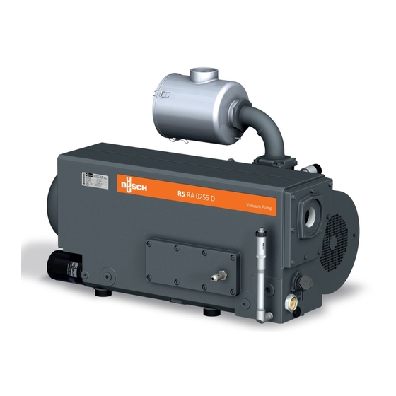
- Page 1 Instruction Manual R5 ATEX Oil-Lubricated Rotary Vane Vacuum Pumps RA 0165 D, RA 0205 D, RA 0255 D, RA 0305 D Ateliers Busch S.A. Zone industrielle, 2906 Chevenez Switzerland 0870570604/-0011_en / Original instructions / Modifications reserved 12/03/2021...
-
Page 2: Table Of Contents
Table of Contents Table of Contents 1 Safety ............................4 2 Product Description ........................5 2.1 Operating Principle ......................6 2.2 Application........................6 2.3 Start Controls ........................6 2.4 Accessories ........................7 2.4.1 Gas Ballast Valve ....................7 2.4.2 Inlet Filter ......................7 2.4.3 Water-oil Heat Exchanger .................. - Page 3 Table of Contents 8 Overhaul...........................29 9 Decommissioning ........................29 9.1 Dismantling and Disposal ....................29 10 Spare Parts..........................30 11 Troubleshooting ........................30 12 Technical Data ..........................33 13 Oil ............................34 14 EU Declaration of Conformity....................35 0870570604_RA0165-0305D_Ex_-0011_IM_en...
-
Page 4: Safety
Safety Prior to handling the machine, this instruction manual should be read and understood. If anything needs to be clarified, please contact your Busch representative. Read this manual carefully before use and keep for future reference. This instruction manual remains valid as long as the customer does not change anything on the product. -
Page 5: Product Description
Product Description | 2 Product Description NOTE Technical term. In this instruction manual, we consider that the term ‘machine’ refers to the ‘vacuum pump’. NOTE Illustrations In this instruction manual the illustrations may differ from the machine appearance. TSA or PSA or TSA or LS-0201... -
Page 6: Operating Principle
The machine is designed for indoor installation, in case of outdoor installation, ask your Busch representative in order to take specific precautions. In case Busch delivered the machine without motor and coupling, the following must be observed: • In regards to its explosive atmosphere protection class, the motor and the coup- ling must have at least the same ATEX classification as the machine for the outside area “Outside (o)”. -
Page 7: Accessories
Product Description | 2 2.4 Accessories NOTE Depending on the ATEX classification of the machine, some of the following accessories may be mandatory, see ATEX Classifications and Associated Accessories [► 8]. 2.4.1 Gas Ballast Valve The gas ballast valve mixes the process gas with a limited quantity of ambient air to counteract the condensation of vapour inside the machine. -
Page 8: Explanation Of Atex Classification
2 | Product Description 2.5 Explanation of ATEX Classification The ATEX classification is written on the nameplate of the machine (NP), see below a marking example: Type of protection Explosion group inside the machine Equipment category for explosive dust Temperature class inside the machine (T3=200°C) Equipment category for explosive gases inside the machine Equipment protection level gas Equipment group II (not for mining application) -
Page 9: P&Id "Piping And Instrumentation Diagram
Transport | 3 2.6.2 P&ID "Piping and Instrumentation Diagram" P&ID for classification B , C and E TSA+ 0101 0101 Optional PSA+ 0301 0201 0301 Optional TSA+ 0104 P&ID for classification D P&ID for classification A TSA+ 0101 0101 Optional PSA+ 0301 0201... -
Page 10: Storage
4 | Storage Machine weight: see the technical data or the nameplate (NP) • Check the machine for transport damage. If the machine is secured to a base plate: • Remove the machine from the base plate. Storage • Seal all apertures with adhesive tape or reuse provided caps. Version with water-oil heat exchanger: •... -
Page 11: Installation
Installation | 5 Installation 5.1 Installation Conditions WARNING The installation conditions are not respected in an ATEX environment. Risk of severe injury! Risk of explosion! • Take care that the installation conditions are met. NOTICE Use of the machine outside of the permitted installation conditions. Risk of premature failure! Loss of efficiency! •... -
Page 12: Connecting Lines / Pipes
Water Connection (Optional) [► 13]. If the machine is installed at an altitude greater than 1000 meters above sea level: • Contact your Busch representative, the motor should be derated or the ambient temperature limited. Make sure that the monitoring devices are correctly connected and integrated into a control system such that operation of the machine will be inhibited if the safety limit val- ues are exceeded, see Electrical Connection of the Monitoring Devices [► 19]. -
Page 13: Discharge Connection
Depending on the specific order, other connection dimensions may apply. If the machine is used as part of a vacuum system: • Busch recommends the installation of an isolation valve in order to prevent the oil from flowing back to the vacuum system. - Page 14 5 | Installation The thermostatic valve (TV) is used to control the water flow in order to keep a stable machine temperature. The factory default adjustment of the thermostatic valve (TV) is set in position 2 (approx. 75°C oil temperature). The pressure switch (PS) is used to monitor the presence of water at the cooling system of the machine.
-
Page 15: Earth Connection
Risk of premature failure! Loss of efficiency! • Only use an oil type which has previously been approved and recommended by Busch. For oil type and oil capacity see Technical Data [► 33] and Oil [► 34]. 1x o-ring, part no.: 0486 000 513... -
Page 16: Fitting The Coupling
5 | Installation 5.5 Fitting the Coupling Coupling hub (machine side) Coupling sleeve Coupling hub (motor side) Radial screw Max. admissible torque: 10 Nm Machine type Coupling size Value “E” (mm) Value “L” (mm) RA 0165 D RA 0205 D ®... -
Page 17: Electrical Connection
• Busch recommends installing a D-curve circuit breaker. • Make sure that the motor of the machine will not be affected by electric or electro- magnetic disturbance from the mains; if necessary seek advice from Busch. • Connect the protective earth conductor. - Page 18 5 | Installation Delta connection (low voltage): Star connection (high voltage): Double star connection, multi-voltage Star connection, multi-voltage motor motor with 9 pins (low voltage): with 9 pins (high voltage): Double star connection, multi-voltage Star connection, multi-voltage motor motor with 12 pins (low voltage): with 12 pins (high voltage): Delta connection, multi-voltage motor with 12 pins (middle voltage):...
-
Page 19: Electrical Connection Of The Monitoring Devices
Installation | 5 5.7 Electrical Connection of the Monitoring Devices NOTE In order to prevent potential nuisance alarms, Busch allows that the control system is configured with a time delay of 2 seconds. NOTE The accessories below are considered as standard. -
Page 20: Wiring Diagram Pressure Switch
5 | Installation 5.7.3 Wiring Diagram Pressure Switch Part no.: 0653 539 030 Supplier reference: United Electric Controls H100 (100 Series) Maintenance procedure: Procedure B P&ID position: PS+/0301 Electrical data: = 49 VDC ; I = 3 A ; L = 0 µH ; C = 0 pF Contact: Normally closed Switch point: P (PS+/0301) = 1500 hPa (mbar) abs. -
Page 21: Wiring Diagram Pressure Switch Of Water-Oil Heat Exchanger (Optional)
Installation | 5 5.7.6 Wiring Diagram Pressure Switch of Water-oil Heat Exchanger (Optional) Part no.: 0653 000 002 Electrical data: P > U = 230 VAC ; I = 1 A U = 24 … 100 VDC ; I = 0.5 … 2 A Contact: Normally open Switch point: = 2 bar (relative) ►... -
Page 22: Commissioning
6 | Commissioning Commissioning NOTICE The machine can be shipped without oil. Operation without oil will ruin the machine in short time! • Prior to commissioning, the machine must be filled with oil, see Filling Oil [► 15]. CAUTION During operation the surface of the machine may reach temperatures of more than 70°C. -
Page 23: Conveying Condensable Vapours
Maintenance | 7 6.1 Conveying Condensable Vapours Water vapour within the gas flow is tolerated within certain limits. The conveyance of other vapours shall be agreed upon with Busch. If condensable vapours are to be conveyed: • Close the isolation •... -
Page 24: Maintenance Schedule
Risk of injuries! Risk of premature failure and loss of efficiency! • Respect the maintenance intervals or ask your Busch representative for service. • Shut down the machine and lock against inadvertent start up. • Vent the connected lines to atmospheric pressure. -
Page 25: Oil Level Inspection
NOTICE Use of an inappropriate oil. Risk of premature failure! Loss of efficiency! • Only use an oil type which has previously been approved and recommended by Busch. 1x o-ring, part no.: 0486 000 505 Drain pan 0870570604_RA0165-0305D_Ex_-0011_IM_en 25 / 36... - Page 26 7 | Maintenance Busch genuine spare parts 1x oil filter (OF), part no.: 0531 000 001 Oil filter wrench For oil type and oil capacity see Technical Data [► 33] and Oil [► 34]. 1x o-ring, part no.: 0486 000 513 Check oil level...
-
Page 27: Exhaust Filter Change
Maintenance | 7 7.4 Exhaust Filter Change 13 mm wrench Remove filter material (FM) 1x flat gasket Busch genuine spare parts part no.: 0481 523 005 4x exhaust filter (EF) part no.: 0532 141 269 13 mm wrench Max. admissible... -
Page 28: Coupling Maintenance
7 | Maintenance 7.5 Coupling Maintenance • Check the coupling backlash and carry out a visual check. • Please refer to the coupling instruction manual (attached to the ATEX Accessories Book) for detailed information in order to carry out a correct inspection and mainten- ance. -
Page 29: Overhaul
• Decontaminate the machine as much as possible and state the contamination status in a ‘Declaration of Contamination’. Busch will only accept machines that come with a completely filled in and legally binding signed ‘Declaration of Contamination’ (form downloadable from www.buschvacuum.com). -
Page 30: Spare Parts
Use of non-Busch genuine spare parts. Risk of premature failure! Loss of efficiency and ATEX compliance! • The exclusive use of Busch genuine spare parts and consumables is recommended for the correct functioning of the machine and to validate the warranty. Spare parts kit Description Part no. - Page 31 The inlet filter cartridge (op- • Replace the inlet filter tional) is partially clogged. cartridge. Internal parts are worn or • Repair the machine (con- damaged. tact Busch). The machine runs very nois- Worn coupling (CPL). • Replace the coupling ily. (CPL). Stuck vanes.
- Page 32 (EF) and the o-rings. The float valve (FV) does • Check float valve and the not work properly. oil return line, repair it if necessary (contact Busch). Abnormal oil consumption. Oil leaks. • Replace seals (contact Busch). The float valve (FV) does •...
-
Page 33: Technical Data
Technical Data | 12 12 Technical Data RA 0165 D RA 0205 D RA 0255 D RA 0305 D Nominal pumping speed m³/h 160 / 190 200 / 240 250 / 300 300 / 360 (50Hz / 60Hz) Ultimate pressure 0.1 ... -
Page 34: Oil
Switch point / Trip signal Oil temperature [°C] In case of unfavourable ambient temperature, other oil viscosities may be used. Please consult your Busch repre- sentative for more details. To know which oil has been filled in the machine, please refer to the nameplate (NP). -
Page 35: Eu Declaration Of Conformity
This Declaration of Conformity and the CE-mark affixed to the nameplate are valid for the machine within the Busch scope of delivery. This Declaration of Conformity is issued under the sole responsibility of the manufacturer. When this machine is integrated into a superordinate machinery the manufacturer of the superordinate machinery (this can be the operating company, too) must conduct the conformity assessment process for the superordinate machine or plant, issue the Declaration of Conformity for it and affix the CE-mark. - Page 36 Chile Israel Portugal United Arab Emirates info@busch.cl service_sales@busch.co.il busch@busch.pt sales@busch.ae China Italy Romania United Kingdom info@busch-china.com info@busch.it office@buschromania.ro sales@busch.co.uk Colombia Japan Russia info@buschvacuum.co info@busch.co.jp info@busch.ru info@buschusa.com Czech Republic Korea Singapore info@buschvacuum.cz busch@busch.co.kr sales@busch.com.sg www.buschvacuum.com 0870570604/-0011_en / © Ateliers Busch S.A.
Need help?
Do you have a question about the R5 ATEX and is the answer not in the manual?
Questions and answers