Table of Contents
Advertisement
Quick Links
Advertisement
Table of Contents

Related Manuals for BUSCH R5 Oxygen


Summary of Contents for BUSCH R5 Oxygen
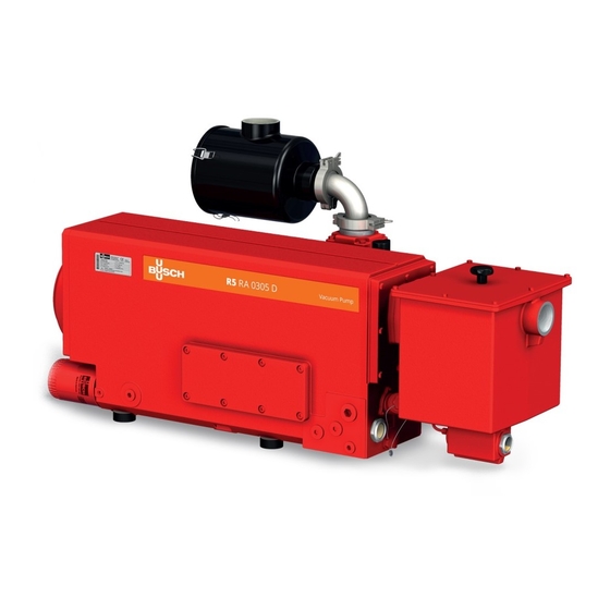
- Page 1 Instruction Manual R5 Oxygen Oil-Lubricated Rotary Vane Vacuum Pumps RA 0165 D, RA 0205 D, RA 0255 D, RA 0305 D Ateliers Busch S.A. Zone industrielle, 2906 Chevenez Switzerland 0870201428/-0004_en / Original instructions / Modifications reserved 18/03/2021...
-
Page 2: Table Of Contents
Table of Contents Table of Contents 1 Safety ............................4 2 Product Description ........................5 2.1 Operating Principle ......................6 2.2 Application........................6 2.3 Start Controls ........................6 2.4 Standard Accessories ......................6 2.4.1 Gas Ballast Valve ....................6 2.5 Optional Accessories ......................7 2.5.1 Inlet Filter ...................... - Page 3 Table of Contents 10 Spare Parts..........................27 11 Troubleshooting ........................28 12 Technical Data ..........................30 13 Oil ............................31 14 EU Declaration of Conformity....................32 0870201428_RA0165-0305D_O2_-0004_IM_en...
-
Page 4: Safety
Safety Prior to handling the machine, this instruction manual should be read and understood. If anything needs to be clarified, please contact your Busch representative. Read this manual carefully before use and keep for future reference. This instruction manual remains valid as long as the customer does not change anything on the product. -
Page 5: Product Description
Product Description | 2 Product Description AHE, AF Suction connection Motor terminal box Discharge connection Directional arrow Oil fill plug Exhaust filter Oil sight glass Nameplate Oil drain plug Oil filter Eye bolt Axial fan Gas ballast valve Oil separator Air-oil heat exchanger Additional oil separator Lead seal... -
Page 6: Operating Principle
(volume content greater than 21% and up to 100%). Conveying of other media leads to an increased thermal and/or mechanical load on the machine and is permissible only after a consultation with Busch. The machine is intended for the placement in a non-potentially explosive environment. -
Page 7: Optional Accessories
Product Description | 2 2.5 Optional Accessories 2.5.1 Inlet Filter The inlet filter protects the machine against dust and other solids in the process gas. The inlet filter is available with a paper or polyester cartridge. The clamped design makes it easy to adjust the position to the installation and the o-ring sealing guaranties the tightness. -
Page 8: Transport
3 | Transport Transport WARNING Suspended load. Risk of severe injury! • Do not walk, stand or work under suspended loads. WARNING Lifting the machine using the motor eye bolt. Risk of severe injury! • Do not lift the machine using the eye bolt fitted to the motor. Only lift the machine as shown. -
Page 9: Storage
Storage | 4 Storage • Seal all apertures with adhesive tape or reuse provided caps. Version with water-oil heat exchanger: • Make sure that the cooling water has been completely removed, see Decommis- sioning [► 26]. If the machine is to be stored for more than 3 months: •... -
Page 10: Connecting Lines / Pipes
Water Connection (Optional) [► 12]. If the machine is installed at an altitude greater than 1000 meters above sea level: • Contact your Busch representative, the motor should be derated or the ambient temperature limited. If the machine is equipped with monitoring devices or sensors: •... -
Page 11: Suction Connection
Depending on the specific order, other connection dimensions may apply. If the machine is used as part of a vacuum system: • Busch recommends the installation of an isolation valve in order to prevent the oil from flowing back to the vacuum system. -
Page 12: Cooling Water Connection (Optional)
5 | Installation 5.2.3 Cooling Water Connection (Optional) Water-oil heat exchanger without inlet accessories Water-oil heat exchanger with inlet accessories Cooling water inlet Pressure switch Cooling water outlet Water bypass valve Water-oil heat exchanger Water filter Thermostatic valve The thermostatic valve (TV) is used to control the water flow in order to keep a stable machine temperature. -
Page 13: Filling Oil
Risk of fire! • Only use oil approved by Busch and suitable for oxygen application, see Oil [► 31]. At delivery, the machine is already filled with specific oil "Busch YLC 250 B" which is suitable for oxygen application. A lead seal is applied on the oil fill plug (OFP) and the oil drain plug (ODP) in order to prevent wrong material from being filled in. -
Page 14: Fitting The Coupling
(see Technical Data [► 30]). Seek advice from your Busch representative. • Make sure that the power supply for the motor is compatible with the data on the nameplate of the motor. -
Page 15: Wiring Diagram Three-Phase Motor
• Busch recommends installing a D-curve circuit breaker. • Make sure that the motor of the machine will not be affected by electric or electro- magnetic disturbance from the mains; if necessary seek advice from Busch. • Connect the protective earth conductor. -
Page 16: Electrical Connection Of The Monitoring Devices
12 pins (middle voltage): 5.6 Electrical Connection of the Monitoring Devices NOTE In order to prevent potential nuisance alarms, Busch recommends that the control system is configured with a time delay of at least 20 seconds. 5.6.1 Wiring Diagram Level Switch (Optional) Part no.: 0652 569 236... -
Page 17: Wiring Diagram Temperature Switch "Oil" (Optional)
Installation | 5 5.6.2 Wiring Diagram Temperature Switch "Oil" (Optional) Part no.: 0651 563 747 Connector: M12x1, 4-pin Electrical data: U = ≤ 250 V AC/DC (50/60 Hz) ; I = ≤ 1 A 1 = Brown ; 2 = White ; Switch point: 3 = Blue ;... -
Page 18: Commissioning
If there is a suspicion that the machine or the oil is contaminated with organic material: • The machine must be removed from service and cleaned by specialists (contact your Busch representative). CAUTION During operation the surface of the machine may reach temperatures of more than 70°C. -
Page 19: Conveying Condensable Vapours
6.1 Conveying Condensable Vapours Water vapour within the gas flow is tolerated within certain limits. The conveyance of other vapours shall be agreed upon with Busch. If condensable vapours are to be conveyed: • Close the isolation • Open the isolation... - Page 20 7 | Maintenance WARNING Use of non-Busch genuine spare parts. Risk of fire! • Only use Busch spare parts approved by Busch and suitable for oxygen application. WARNING Machines contaminated with hazardous material. Risk of poisoning! Risk of infection! If the machine is contaminated with hazardous material: •...
-
Page 21: Maintenance Schedule
If the machine is equipped with an water-oil heat exchanger (WHE): • Check and/or clean the water cooling sys- tem. • Contact Busch for an inspection. Every 5 years If required, overhaul the machine. 7.2 Oil Level Inspection • Shut down the machine. -
Page 22: Oil Colour Inspection
If the oil becomes dark or looks different from the initial colour: • Change the oil immediately, see Oil and Oil Filter Change [► 22]. You can consult your Busch representative in order to find out why this colour change has occurred. - Page 23 Maintenance | 7 1x o-ring, part no.: 0482 509 010 Remove lead seal (if authorized) Drain pan Busch genuine spare parts 1x oil filter (OF), part no.: 0531 531 532 Oil filter wrench 0870201428_RA0165-0305D_O2_-0004_IM_en 23 / 36...
-
Page 24: Exhaust Filter Change
7 | Maintenance For oil type and oil capacity see Technical Data [► 30] and Oil [► 31]. Reapply lead seal 1x o-ring, part no.: 0482 509 012 Check oil level 7.5 Exhaust Filter Change 13 mm wrench Remove demister (DR) 24 / 36 0870201428_RA0165-0305D_O2_-0004_IM_en... -
Page 25: Air Heat Exchanger Cleaning
Maintenance | 7 1x flat gasket Busch genuine spare parts part no.: 0481 523 005 4x exhaust filter (EF) part no.: 0532 141 269 13 mm wrench Max. admissible O-ring torque: 21 Nm Check 4x o-ring 1x demister (DR) part no.: 0534 562 240 7.6 Air Heat Exchanger Cleaning... -
Page 26: Overhaul
• Decontaminate the machine as much as possible and state the contamination status in a ‘Declaration of Contamination’. Busch will only accept machines that come with a completely filled in and legally binding signed ‘Declaration of Contamination’ (form downloadable from www.buschvacuum.com). -
Page 27: Spare Parts
Use of non-Busch genuine spare parts. Risk of premature failure! Loss of efficiency! • The exclusive use of Busch genuine spare parts and consumables is recommended for the correct functioning of the machine and to validate the warranty. WARNING Use of non-Busch genuine spare parts. -
Page 28: Troubleshooting
• Clean the inlet screen (IS). suction connection. tially clogged. The inlet filter cartridge (op- • Replace the inlet filter tional) is partially clogged. cartridge. Internal parts are worn or • Repair the machine (con- damaged. tact Busch). 28 / 36 0870201428_RA0165-0305D_O2_-0004_IM_en... - Page 29 (EF) and the o-rings. The float valve (FV) does • Check float valve and the not work properly. oil return line, repair it if necessary (contact Busch). Abnormal oil consumption. Oil leaks. • Replace seals (contact Busch). The float valve (FV) does •...
-
Page 30: Technical Data
12 | Technical Data 12 Technical Data RA 0165 D RA 0205 D RA 0255 D RA 0305 D Nominal pumping speed m³/h 160 / 190 200 / 240 250 / 300 300 / 360 (50Hz / 60Hz) Ultimate pressure 0.1 ... -
Page 31: Oil
Oil | 13 13 Oil YLC 250 B Part number 0.5 L packaging (~1 kg) 0831 131 400 Part number 1.0 L packaging (~2 kg) 0831 108 878 Part number 5.0 L packaging (~10 kg) 0831 108 879 Warning signal Oil temperature [°C] Switch point / Trip signal Oil temperature [°C] To know which oil has been filled in the machine, please refer to the nameplate (NP). -
Page 32: Eu Declaration Of Conformity
This Declaration of Conformity and the CE-mark affixed to the nameplate are valid for the machine within the Busch scope of delivery. This Declaration of Conformity is issued under the sole responsibility of the manufacturer. When this machine is integrated into a superordinate machinery the manufacturer of the superordinate machinery (this can be the operating company, too) must conduct the conformity assessment process for the superordinate machine or plant, issue the Declaration of Conformity for it and affix the CE-mark. - Page 33 Note...
- Page 34 Note...
- Page 35 Note...
- Page 36 Chile Israel Portugal United Arab Emirates info@busch.cl service_sales@busch.co.il busch@busch.pt sales@busch.ae China Italy Romania United Kingdom info@busch-china.com info@busch.it office@buschromania.ro sales@busch.co.uk Colombia Japan Russia info@buschvacuum.co info@busch.co.jp info@busch.ru info@buschusa.com Czech Republic Korea Singapore info@buschvacuum.cz busch@busch.co.kr sales@busch.com.sg www.buschvacuum.com 0870201428/-0004_en / © Ateliers Busch S.A.
Need help?
Do you have a question about the R5 Oxygen and is the answer not in the manual?
Questions and answers