
Subscribe to Our Youtube Channel
Related Manuals for ASROCK IMB-193


Summary of Contents for ASROCK IMB-193
- Page 1 IMB-193 User Manual Version 1.0 Published April 2016 Copyright©2016 ASRock INC. All rights reserved.
- Page 2 (including damages for loss of profits, loss of business, loss of data, interruption of business and the like), even if ASRock has been advised of the possibility of such damages arising from any defect or error in the documentation or product.
- Page 3 CAUTION: RISK OF EXPLOSION IF BATTERY IS REPLACED BY AN INCORRECT TYPE. DISPOSE OF USED BATTERIES ACCORDING TO THE INSTRUCTIONS.
-
Page 4: Table Of Contents
Contents 1 Introduction ............5 1.1 Package Contents ............5 1.2 Specifications ..............6 1.3 Motherboard Layout ............8 1.4 I/O Panel ................ 10 2 Installation ............11 2.1 Screw Holes ..............11 2.2 Pre-installation Precautions ........... 11 2.3 Installation of Memory Modules (SO-DIMM) ....12 2.4 Expansion Slots ............ -
Page 5: Introduction
In case any modifications of this manual occur, the updated version will be available on ASRock website without further notice. You may find the latest VGA cards and CPU support lists on ASRock website as well. ASRock website http://www.asrock.com If you require technical support related to this motherboard, please visit our website for specific information about the model you are using. -
Page 6: Specifications
1.2 Specifications Form Dimensions Mini-ITX (6.7-in x 6.7-in) Factor ® Socket LGA1151 for Intel Core i7/i5/i3/Celeron (Skylake-S) Core (By CPU, Max 4) Processor Number System Max Speed (By CPU) L2 Cache (By CPU) ® Chipset Intel H110 BIOS UEFI PCIe 1 x PCIe x4 slot Expansion Mini-PCIe... - Page 7 Serial PS/2 4 x USB 2.0 (2 x 2.54 pitch header) LVDS/ inverter 4 x RS-232 (COM1 supports RS- Serial 232/422/485) SATA Internal mPCIe Connector Parallel mSATA IrDA GPIO 4 x GPI, 4 x GPO SATA PWR Output Con Speaker Header Watchdog Interval...
-
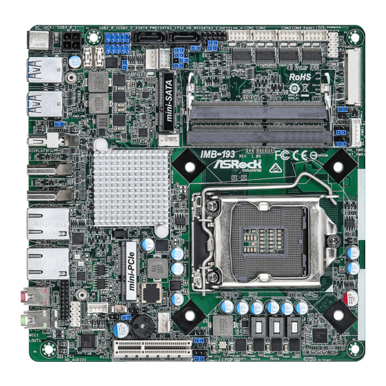
Page 8: Motherboard Layout
SET_CM2 T: USB0 JGPIO_PWR1 B: USB1 PS2_KB_MS1 SATA_PWR1 PWR_SET1 USB2_PWR1 USB 3.0 T: USB2 B: USB3 DDR4_B1 PNL_PWR1 USB3_PWR1 DDR4_A1 CPU_FAN1 IMB-193 HDMI2 Industrial HDMI3 LAN1 LAN2 BIOS Chip Mic In SPEAKER1 BUZZ2 Line Out BUZZ1 AUDIO CPU_FAN2 CODEC CLRMOS2... - Page 9 1 : ATX Power Connector 2 : USB2.0 Switch Header 3 : USB2.0 Headers (USB2_0_1, USB2_2_3) 4 : SATA3 Connectors (SATA3_1, SATA3_2) 5 : COM1, 2, 3, 4 PWR Setting Jumpers 6 : Digital Input / Output Pin Header 7 : ATX/AT Mode Jumper (PWR_JP1) 8 : COM Port Header (COM1) 9 : COM Port Header (COM2) 10 : COM Port Header (COM3)
-
Page 10: I/O Panel
1.4 I/O Panel DC Jack (+19V only) (DC_JACK1) HDMI Port (HDMI3) USB 3.0 Ports (USB3_0_1) LAN RJ-45 Port* USB 3.0 Ports (USB3_2_3) LAN RJ-45 Port* DisplayPort (DISPLAY1) Microphone (Pink) HDMI Port (HDMI2) Line out (Lime) * There are two LED next to the LAN port. Please refer to the table below for the LAN port LED indications. -
Page 11: Installation
Chapter 2: Installation This is a Mini-ITX form factor (6.7” x 6.7”, 17.0 x 17.0 cm) motherboard. Before you install the motherboard, study the configuration of your chassis to ensure that the motherboard fits into it. Make sure to unplug the power cord before installing or removing the motherboard. -
Page 12: Installation Of Memory Modules (So-Dimm)
2.3 Installation of Memory Modules (SO-DIMM) IMB-193 provides two 204-pin DDR4 (Double Data Rate 4) SO-DIMM slots. Step 1. Align a SO-DIMM on the slot such that the notch on the SO-DIMM matches the break on the slot. 1. The SO-DIMM only fits in one correct orientation. It will cause permanent damage to the motherboard and the SO-DIMM if you force the SO-DIMM into the slot at incorrect orientation. -
Page 13: Expansion Slots
2.4 Expansion Slots (mini-PCIe, mini-SATA and PCI Express Slots) There is 1 mini-PCIe slot, 1 mini-SATA slot and 1 PCI Express slot on this mother- board. mini-PCIe slot: MINI_PCIE1 (mini-PCIe slot; half size) is used for PCI Express mini cards. mini-SATA slot: MINI_SATA1 (mini-SATA slot;... -
Page 14: Jumpers Setup
2.5 Jumpers Setup The illustration shows how jumpers are setup. When the jumper cap is placed on pins, the jumper is “Short”. If no jumper cap is placed on pins, the jumper is “Open”. The illustration shows a 3-pin jumper whose pin1 and pin2 are “Short”... - Page 15 Digital Input / Output Default Value Setting 1-2 : Pull-High (+3V) 2-3 : Pull-Low (3-pin JGPIO_SET1) (see p.8, No. 14) Speaker Control Signal Name GPIO_VOL_DW (3-pin AMP_CTL1) (see p.8, No. 20) GPIO_VOL_UP Backlight Control Level (CON_LBKLT_CTL) 1-2 : +3.3V 2-3 : +5V (3-pin BLT_PWM1) (see p.8, No.
-
Page 16: Onboard Headers And Connectors
2.6 Onboard Headers and Connectors Onboard headers and connectors are NOT jumpers. Do NOT place jumper caps over these headers and connectors. Placing jumper caps over the headers and connectors will cause permanent damage of the motherboard! CPU Fan Connectors Please connect the CPU fan cable to the connector and (4-pin CPU_FAN1) - Page 17 COM Port Headers (10-pin COM1: see p.8, No. 8) (10-pin COM2: see p.8, No. 9) (10-pin COM3: see p.8, No. 10) (10-pin COM4: see p.8, No. 11) Signal Signal Signal Signal Signal Name Name Name Name Name CCTS# DDSR# DDTR# RRXD RRTS# TTXD...
- Page 18 PLED (System Power LED): Connect to the power status indicator on the chassis front panel. The LED is on when the system is operating. The LED keeps blinking when the sys- tem is in S1/S3 sleep state. The LED is off when the system is in S4 sleep state or powered off (S5).
- Page 19 1. High Definition Audio supports Jack Sensing, but the panel wire on the chassis must support HDA to function correctly. Please follow the instruction in our manual and chassis manual to install your system. 2. If you use AC’97 audio panel, please install it to the front panel audio header as below: A.
- Page 20 eDP Connector Signal Name (40-pin EDP1) LCD_BLT_VCC LCD_BLT_VCC (see p.8 No. 15) LCD_BLT_VCC LCD_BLT_VCC SMB_CLK SMB_DATA CON_LBKLT_CTL CON_LBKLT_EN eDP_HPD_CON LCD_VCC LCD_VCC LCD_VCC LCD_VCC eDP_AUX#_CON eDP_AUX_CON eDP_TX0_CON eDP_TX#0_CON eDP_TX1_CON eDP_TX#1_CON eDP_TX2_CON eDP_TX#2_CON eDP_TX3_CON eDP_TX#3_CON SATA Power Connector Please connect a SATA power cable to this connector.
- Page 21 Backlight Power Connector Signal Name (8-pin BLT_PWR1) (see p.8, No. 17) BL CTL BL EN LCD_BLT_VCC LCD_BLT_VCC 3W Audio AMP Output Wafer (4-pin SPEAKER1) (see p.8 No. 29) Signal Signal Signal Signal Name Name Name Name SPK R- SPK R+ SPK L+ SPK L- Buzzer...
-
Page 22: Uefi Setup Utility
Chapter 3: UEFI SETUP UTILITY 3.1 Introduction This section explains how to use the UEFI SETUP UTILITY to configure your system. The UEFI chip on the motherboard stores the UEFI SETUP UTILITY. You may run the UEFI SETUP UTILITY when you start up the computer. Please press <F2>... -
Page 23: Navigation Keys
3.1.2 Navigation Keys Please check the following table for the function description of each navigation key. Navigation Key(s) Function Description Moves cursor left or right to select Screens Moves cursor up or down to select items + / - To change option for the selected items <Enter>... -
Page 24: Advanced Screen
3.3 Advanced Screen In this section, you may set the configurations for the following items: CPU Configu- ration, Chipset Configuration, Storage Configuration, Super IO Configuration, ACPI Configuration and USB Configuration. Setting wrong values in this section may cause the system to malfunction. Instant Flash Instant Flash is a UEFI flash utility embedded in Flash ROM. -
Page 25: Cpu Configuration
3.3.1 CPU Configuration Intel Hyper Threading Technology To enable this feature, a computer system with an Intel processor that sup- ports Hyper-Threading technology and an operating system that includes ® ® optimization for this technology, such as Microsoft Windows 7 / 8 / 8.1 / ®... - Page 26 ® [Enabled] and [Disabled]. If you install Windows 7 / 8 / 8.1 / 10 and want to enable this function, please set this item to [Enabled]. This item will be hidden if the current CPU does not support Intel SpeedStep technology. Please note that enabling this function may reduce CPU voltage and lead to system stability or compatibility issues with some power supplies.
-
Page 27: Chipset Configuration
3.3.2 Chipset Configuration Primary Graphics Adapter This allows you to select [Onboard] or [PCI Express] as the boot graphic adapter priority. The default value is [PCI Express]. Top of Lower usable DRAM Set the maximum value of TOLUD. Set this item to Dynamic to allow TOLUD to adjust automatically based on the largest MMIO length of the installed graphic controller. - Page 28 Onboard HD Audio Select [Auto], [Enabled] or [Disabled] for the onboard HD Audio feature. If you select [Auto], the onboard HD Audio will be disabled when PCI Sound Card is plugged. Front Panel Select [HD] or [AC 97] for the onboard HD Audio Front Panel. Deep Sleep Mobile platforms support Deep S4/S5 in DC only and desktop platforms support Deep S4/S5 in AC only.
-
Page 29: Storage Configuration
3.3.3 Storage Configuration SATA Controller(s) Use this item to enable or disable the SATA Controller feature. SATA Mode Selection Use this to select SATA mode. The default value is [AHCI Mode]. AHCI (Advanced Host Controller Interface) supports NCQ and other new features that will improve SATA disk perfor- mance but IDE mode does not have these advantages. -
Page 30: Super Io Configuration
3.3.4 Super IO Configuration COM1 Configuration Use this to set parameters of COM1. Select COM1 port type: [RS232], [RS422] or [RS485]. COM2 Configuration Use this to set parameters of COM2. COM3 Configuration Use this to set parameters of COM3. COM4 Configuration Use this to set parameters of COM4. -
Page 31: Acpi Configuration
3.3.5 ACPI Configuration Suspend to RAM Use this item to select whether to auto-detect or disable the Suspend-to- RAM feature. Select [Auto] will enable this feature if the OS supports it. ACPI HPET Table Use this item to enable or disable ACPI HPET Table. The default value is [Enabled]. -
Page 32: Usb Configuration
3.3.6 USB Configuration Legacy USB Support Use this option to select legacy support for USB devices. There are four configuration options: [Enabled], [Auto] and [UEFI Setup Only]. The default value is [Enabled]. Please refer to below descriptions for the details of these four options: [Enabled] - Enables support for legacy USB. -
Page 33: Hardware Health Event Monitoring Screen
3.4 Hardware Health Event Monitoring Screen In this section, it allows you to monitor the status of the hardware on your system, including the parameters of the CPU temperature, motherboard temperature, CPU fan speed, chassis fan speed, and the critical voltage. CPU_FAN1 Setting This allows you to set CPU fan 1’s speed. -
Page 34: Security Screen
3.5 Security Screen In this section, you may set, change or clear the supervisor/user password for the system. Supervisor Password Set or change the password for the administrator account. Only the ad- ministrator has authority to change the settings in the UEFI Setup Utility. Leave it blank and press enter to remove the password. -
Page 35: Boot Screen
3.6 Boot Screen In this section, it will display the available devices on your system for you to config- ure the boot settings and the boot priority. Boot From Onboard LAN Use this item to enable or disable the Boot From Onboard LAN feature. Setup Prompt Timeout This shows the number of seconds to wait for setup activation key. - Page 36 CSM (Compatibility Support Module) Enable to launch the Compatibility Support Module. Please do not disable ® unless you’re running a WHCK test. If you are using Windows 8.1 / 8 64- bit and all of your devices support UEFI, you may also disable CSM for faster boot speed.
-
Page 37: Exit Screen
3.7 Exit Screen Save Changes and Exit When you select this option, it will pop-out the following message, “Save configuration changes and exit setup?” Select [OK] to save the changes and exit the UEFI SETUP UTILITY. Discard Changes and Exit When you select this option, it will pop-out the following message, “Discard changes and exit setup?”... -
Page 38: Software Support
Click on a specific item then follow the installation wizard to install it. 4.2.4 Contact Information If you need to contact ASRock or want to know more about ASRock, you’re welcome to visit ASRock’s website at http://www.asrock.com; or you may con-...
Need help?
Do you have a question about the IMB-193 and is the answer not in the manual?
Questions and answers