Sign In
Upload
Download
Table of Contents
Contents
Add to my manuals
Delete from my manuals
Share
URL of this page:
HTML Link:
Bookmark this page
Add
Manual will be automatically added to "My Manuals"
Print this page
×
Bookmark added
×
Added to my manuals
Manuals
Brands
ASROCK Manuals
Motherboard
IMB-190
User manual
ASROCK IMB-190 User Manual
Hide thumbs
1
2
3
Table Of Contents
4
5
6
7
8
9
10
11
12
13
14
15
16
17
18
19
20
21
22
23
24
25
26
27
28
29
30
31
32
33
34
35
36
37
38
39
40
41
42
43
44
page
of
44
Go
/
44
Contents
Table of Contents
Bookmarks
Table of Contents
User Manual
Copyright Notice
Table of Contents
1 Introduction
Package Contents
Specifications
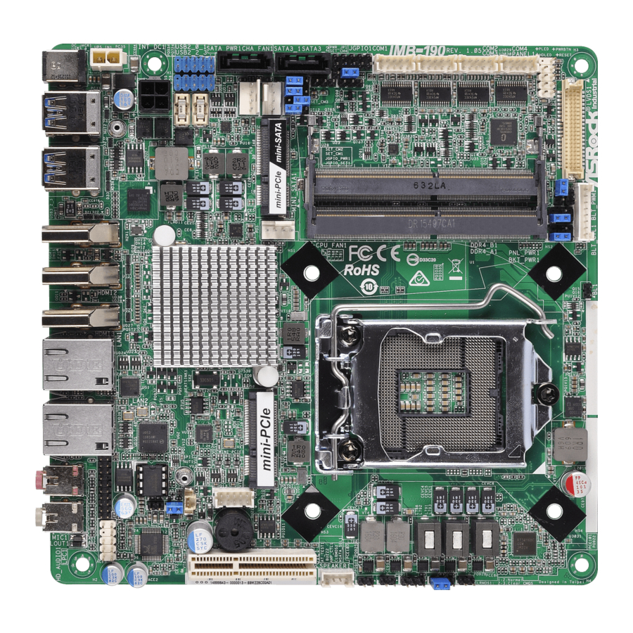
Motherboard Layout
I/O Panel
2 Installation
Screw Holes
Pre-Installation Precautions
Installation of Memory Modules (SO-DIMM)
Expansion Slots
Jumpers Setup
Onboard Headers and Connectors
3 Uefi Setup Utility
Introduction
UEFI Menu Bar
Navigation Keys
Main Screen
Advanced Screen
CPU Configuration
Chipset Configuration
Storage Configuration
AMT Configuration
Super IO Configuration
ACPI Configuration
USB Configuration
Hardware Health Event Monitoring Screen
Security Screen
Boot Screen
Exit Screen
4 Software Support
Install Operating System
Support CD Information
Running Support CD
Drivers Menu
Utilities Menu
Contact Information
Advertisement
Quick Links
1
User Manual
2
Package Contents
3
Motherboard Layout
4
I/O Panel
5
Jumpers Setup
6
Onboard Headers and Connectors
Download this manual
IMB-190
IMB-190-E
IMB-191
User Manual
Version 1.1
Published July 2016
Copyright©2016 ASRock INC. All rights reserved.
1
Table of
Contents
Previous
Page
Next
Page
1
2
3
4
5
Advertisement
Table of Contents
Need help?
Do you have a question about the IMB-190 and is the answer not in the manual?
Ask a question
Questions and answers
Related Manuals for ASROCK IMB-190
Motherboard ASROCK IMB-194-D Jumpers And Headers Setting Manual
(2 pages)
Motherboard ASROCK IMB-194-D Jumpers And Headers Setting Manual
(2 pages)
Motherboard ASROCK IMB-191 User Manual
(44 pages)
Motherboard ASROCK IMB-192 User Manual
(38 pages)
Motherboard ASROCK IMB-192 Settings Manual
Jumpers and headers (2 pages)
Motherboard ASROCK IMB-193 User Manual
(38 pages)
Motherboard ASROCK IMB-199 User Manual
(42 pages)
Motherboard ASROCK IMB-195-D User Manual
(41 pages)
Motherboard ASROCK IMB-196-D User Manual
(42 pages)
Motherboard ASROCK IMB-198 User Manual
(42 pages)
Motherboard ASROCK IMB-197-D User Manual
(42 pages)
Motherboard ASROCK IMB-1212 User Manual
(40 pages)
Motherboard ASROCK IMB-1220 User Manual
(45 pages)
Motherboard ASROCK IMB-155B User Manual
(37 pages)
Motherboard ASROCK IMB-1214 User Manual
(38 pages)
Motherboard ASROCK IMB-1713 User Manual
(55 pages)
This manual is also suitable for:
Imb-190-e
Imb-191
Imb-195
Imb-194-d
Imb-194-l
Table of Contents
Print
Rename the bookmark
Delete bookmark?
Delete from my manuals?
Login
Sign In
OR
Sign in with Facebook
Sign in with Google
Upload manual
Upload from disk
Upload from URL


Need help?
Do you have a question about the IMB-190 and is the answer not in the manual?
Questions and answers