
Subscribe to Our Youtube Channel
Related Manuals for digico SD Series


Summary of Contents for digico SD Series
- Page 1 SD12 Operation Manual User Manual - Getting Started To be read in conjunction with the SD Series Software Reference User Manual Version A for Software Versions 9.0.900+...
- Page 2 SD12 Operation Manual...
- Page 3 Digico UK Ltd. Information in this manual is subject to change without notice, and does not represent a commitment on the part of the vendor. Digico UK Ltd shall not be liable for any loss or damage whatsoever arising from the use of information or any error contained in this manual.
-
Page 4: Table Of Contents
SD12 Operation Manual Contents 1.1 The Console ..................6 1.2 Manual Overview ..................6 1.3 Before You Start ...................7 1.3.1 Worksurface Layout ..............7 1.3.2 Layers and Banks ..............9 1.3.3 Using the Control Surface ............10 1.3.4 The Assigned Channel ............10 1.3.5 The Master Faders ............ - Page 5 SD12 Operation Manual 1.13 Solo Setup ..................31 2.1 DMI Cards ....................29 2.1.2 Fitting DMI Cards ..............29 2.2 MADI DMI Cards..................30 2.2.1 Connecting MADI DMI ............30 2.2.2 Sharing Racks with MADI DMI..........33 2.3 DMI-DANTE Cards ................35 2.4 DMI - ADC - DAC - AES Cards ............36 2.5 DMI - Waves - Hydra Cards ..............37...
-
Page 6: The Console
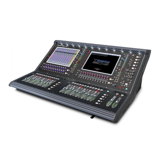
1.1 The Console The Digico SD12 consists of a worksurface, an audio engine and a range of onboard inputs and outputs. This can be connected to mul- tiple Input/Output Rack Units by optical fibre and/or MADI links, which carry all the audio input and output signals. -
Page 7: Before You Start
SD12 - Getting Started 1.3 Before You Start There are certain general operating principles and terms that should be understood before continuing to use this manual. Please read this chapter carefully before proceeding. 1.3.1 Worksurface Layout ............... Left Section ALT Input Switch High and Low Pass Filters Quick Select 4 Band Dynamic Parametric EQ... - Page 8 SD12 - Getting Started Rear Panel Dual PSU Word Clock I/O GPI/O Optocore MADI I/O MIDI IN/OUT/THRU USB Audio (Optional) 8 AES I/O 8 Mic/Line In 8 Line Out DVI O/View Output 4 x Console USB DMI Slot 1 DMI Slot 2 Console Ethernet PC Reset IP Addresses on an SD12...
-
Page 9: Layers And Banks
SD12 - Getting Started 1.3.2 Layers and Banks ..............The SD12's worksurface is divided into Layers and Banks. Each Bank contains twelve channels, and the channels which are currently active on the control surface are defined using the fader bank and bank layer buttons to the right of the Channel Strip section’s fader NOTE: There is also a Master Screen Assign button above the Layer and Bank buttons on the right section which is used to switch the right hand section to diplay the Master Screen A ‘bank’... -
Page 10: Using The Control Surface
SD12 - Getting Started 1.3.3 Using the Control Surface ............. There are two main ways in which all of the functions of the SD12 are accessed: 1. The touchscreen display, which can be controlled directly using a finger, or by using the keyboard and mouse 2. - Page 11 SD12 - Getting Started Once a channel is assigned, all of the controls for that channel which are not displayed within the channel strip itself can be accessed via secondary pop-ups, displayed by touching inside the relevant area of the channel. These pop-ups include controls such as input and output routing and signal processing parameters.
- Page 12 SD12 - Getting Started The controls to the right of the Channel Strip panel allow the Assigned channel to be adjusted: The top half of the channel worksurface controls (down as far as the insert a, insert b and direct buttons, as shown above) control the signal processing parameters which are displayed in the pop-ups accessed by touching in the appropriate section of the active channel.
-
Page 13: The Master Faders
SD12 - Getting Started 1.3.5 The Master Faders ..............By default, the left hand fader of the two in the bottom right corner of the worksurface is assigned to the Master buss, which is the lowest stereo group output by default. Also by default, the right hand fader is assigned to Solo Buss 1 In addition, these faders can be reassigned to control any input channel or buss of your choice using the Layout>Fader Banks panel Press the Assign L or Assign R buttons and the Channel List will be displayed. -
Page 14: Channel Types
SD12 - Getting Started 1.3.6 Channel Types ................ The SD12 has 4 different channel types which are laid out in banks of 12 on the console worksurface and can be identified by their colour. By default, the Input Channels will be assigned to Layer 1 on the left and right sections of the console. The output channels (Groups, Auxes and Matrices) will be assigned to Layer 2. -
Page 15: Hardware Configuration
Rack MAIN MADI OUT connected to the console MADI 1 IN At 48KHz, the console's other MADI Port can be connected to a MADI recorder (See Audio I/O Panel for setup details) or a second DiGiCo Rack or console. 1-15... -
Page 16: Software Configuration
SD12 - Getting Started 1.5 Software Configuration The SD12 has a default setup which means that the new user need not get involved in configuring the desk at this stage. However, here is a brief overview of how the different displays are used in putting together a session. Each of the master displays introduced below are described fully within the rest of the manual. -
Page 17: Audio I/O Overview
SD12 - Getting Started from the channels in the session. This is especially useful when restructuring an existing session to make a new session. The other 'clear' buttons in the display perform similar operations. Aux Sends and Direct Sends : By toggling the state of the Aux Sends and Direct Sends Buttons in the Input Channels section, it is possible to change the default operation of the Aux Sends and Direct Sends. -
Page 18: Opto V220 (Digiracks) And Opto V221 (Sd Racks)
V221 is compatible with SD Racks, SD MiNiRacks, NaNoRacks and DRacks, and cannot be used with DiGiRacks and MiNiRacks. Note: Any type of rack can be used with an SD Series console if it is connected with Coaxial BNC MADI irrespective of the Optocore version that the console is using. -
Page 19: Manual Conforming Of Racks
Standard MADI Connections If you have a standard MADI connection (not a DiGiCo Rack) to your SD12, you can set the console to display the MADI with generic signal names, i.e. MADI 1, MADI 2.. etc. through to MADI 56 (or 64) instead of the usual rack style names. The naming does not affect the signal, but makes routing signals easier. -
Page 20: Rack Sharing
1.5.8 Rack Sharing................In a multi-console system where Racks are connected with MADI and shared between two DiGiCo Consoles, only one of the consoles can take control of the rack, with respect to Gain, Phantom Power and Pads. To overcome this, it is possible to place the SD12 into one... -
Page 21: Saving And Loading Sessions
SD12 - Getting Started 1.6 Saving and Loading Sessions 1.6.1 Save As New File ..............When you change the configuration of a session you should save it to the console's flash drive under a new filename. If the Save Session panel has not appeared automatically after a session restructure then touch the Files button on the Master screen and then press Save As New File. -
Page 22: Audio Sync
SD12 - Getting Started 1.7 Audio Sync To access the Audio Sync Panel, touch the Setup Menu button, followed by Audio Sync. The following window will open… The SD12 will operate at Sample Rates of either 48000Hz (48kHz) or 96000Hz (96kHz), as configured in the Session Structure panel. By default, it is set to clock internally but, if Optocore is fitted, the standard Audio Sync method is Optocore when the entire system uses the device with the lowest Optocore ID (usually ID1) as its sync source. -
Page 23: Routing Basics
SD12 - Getting Started 1.8 Routing Basics 1.8.1 Selecting Inputs & Outputs ........... All channel input, output, insert send and insert return routing is done via routing displays, accessed via the dark grey routing buttons in the channel Setup and Output displays (shown below for an Input channel’s input). Note that multi-channel signals are routed individually, and then collected together as a "Multi Channel"... -
Page 24: Ripple Channels
SD12 - Getting Started Groups: The outputs of the group busses Auxes: The outputs of the auxiliary busses Matrix: The outputs of the matrix busses. Solos: The outputs of the Solo bussses Note: The outputs for the channel being routed are locked out of the signal list Note also that the console views all routes as a single list. -
Page 25: Channel Processing
SD12 - Getting Started 1.9 Channel Processing 1.9.1 Dynamic EQ ................The EQ section comprises four user-configurable parametric filters with Dynamic Control on all Channels and a pair of swept High-pass and Low-pass filters. The EQ is accessed by touching the on screen display to Assign the channel (the colour changes to yellow) and then using the con- trols on the right hand side of the input module. -
Page 26: Dynamics
SD12 - Getting Started 1.9.2 Dynamics................The dynamics are accessed by touching the words Comp or Gate just below the EQ graph on screen to open the dynamics panel. There are two dynamics modules, the first of which can function as a simple compressor, a 3 way multiband compressor, or a de-esser, according to the comp/multi/desser button to its left. -
Page 27: Auxiliaries
SD12 - Getting Started 1.9.3 Auxiliaries ................The auxiliaries can be accessed by pressing the Quick Select Aux button and touching the auxiliary row on screen or using the Screen Scroll buttons on the left of the worksurface Using either of these methods, the highlighted auxiliaries on the input screen will change. The rotary controls and switches beneath the screen are used as auxiliary sends, pans (with 2nd Function ON), On/Off and pre/post switches (with 2nd Function ON). -
Page 28: The Matrix
SD12 - Getting Started 1.10 The Matrix To open the Matrix Inputs panel, touch the Matrix button on the Master Screen. The window that opens allow you to route inputs to the Matrix Output Channels, and set the Matrix crosspoint levels. To route an input, touch the top of the appropriate Matrix column. -
Page 29: Control Groups
SD12 - Getting Started 1.11 Control Groups Any number of input channels and output channels can be connected to one or more of the 12 possible Control Groups. They can then all be operated from a single worksurface control. Changes to the Control Group fader, mute or solo or controls will affect all channels connected to the group. -
Page 30: Multi-Channel Formats
If the Unfold button in the Multi or in a multi-channel buss channel strip is pressed, the component channels will be displayed, and more detailed configuration can be made. See the SD Series Software Reference Manual for more information on Multi Channel formats 1-30... -
Page 31: Solo Setup
SD12 - Getting Started 1.13 Solo Setup The SD12 Solo panel is accessed from a button at the top of the Master Screen. Some of the controls on this panel are duplicated on the worksurface right hand section There are two solo busses and each solo button on the console can be independently assigned to use Solo1, Solo2 or Solo 1+2. Therefore, if the console was being used for Stage monitors, the first solo buss could feed “In-Ear”... -
Page 32: Dmi Cards
DiGiCo SD12 2.1 DMI Cards The Digico SD12 has two option slots on its rear panel for the installation of DMI cards (see below) These cards come in a variety of I/O types. DMI Slot 1 DMI Slot 2 2.1.2 Fitting DMI Cards .............. -
Page 33: Madi Dmi Cards
MADI B has 2 pairs of BNC connectors MADI C has 2 bi-directional Cat5e connectors Both of these cards can be used to connect a Standard MADI stream at 48KHz or 96KHz or an SD-Series DiGiCo Rack with the appro- priate connector (D-Rack, D2-Rack, SD-Rack, SD-MINIRack) Note: Only one DiGiCo Rack can be connected to a single MADI DMI card at one time Note: With SD12 software V9.0.900+, cable redundancy at 48KHz using both the Main and Aux MADI ports on a D2-... - Page 34 DiGiCo SD12 DMI MADI C to D2-Rack at 48KHz Connect DMI card Cat5e socket A to D2-Rack Cat5e Main socket Single SD 12 to D2-Rack with DMI MADI C Card at 48KHz D2-Rack SINGLE CAT5e MAIN MADI CONNECTION DMI MADI C PORT A...
- Page 35 DiGiCo SD12 DMI MADI B to D2-Rack, SD-Rack or SD-MINIRack at 48KHz Connect DMI card BNC IN socket A to D2-Rack BNC OUT MAIN socket Connect DMI card BNC OUT socket A to D2-Rack BNC IN MAIN socket Single SD 12 to D2-Rack with DMI MADI B Card at 48KHz...
- Page 36 DiGiCo SD12 2.2.2 Sharing Racks with MADI DMI..........If the system is running at a sample rate of 48KHz a D2-Rack, SD-Rack or SD-MINIRack can be shared between 2 consoles (Two SD12s or an SD12 and another S or SD-Series console) with the connection system shown below.
- Page 37 SD-Series console with Cat5e connections eg SD9 or SD11) with the connection system shown below. This setup is similar to the one previously described but requires a DiGiCo Little Red Box. The Little Red Box has separate Cat5e connections for: The D-Rack itself The FULL CONNECT "...
-
Page 38: Dmi-Dante Cards
In the picture below, the Dante Controller software displays two DiGiCo DMI Dante devices. The second device in the list is installed in an SD12 and has been manually labelled "DiGiCo SD12". In the Dante Device Config tab the SD12 DMI-Dante card must be set to match the SD12 sample rate at 48KHz or 96KHz Example 1 - Console is Master clock for Dante Network In the Dante Clock Status tab, the SD12 DMI-Dante card is set to Sync To External and Preferred Master. -
Page 39: Dmi - Adc - Dac - Aes Cards
DiGiCo SD12 2.4 DMI - ADC - DAC - AES Cards The DMI-ADC card provides 16 analogue inputs on 2 x 25 way "D" connectors The ADC card is a line card only. There is no microphone amplifier or phantom power available. -
Page 40: Dmi - Waves - Hydra Cards
DiGiCo SD12 2.5 DMI - Waves - Hydra Cards DMI Waves has 64 Inputs an 64 Outputs at both 48KHz and 96KHz - there is no control from the console, just simple routing of audio inputs and outputs. Configuration of this card on the Waves network is done with Waves own software and Control Panels - please refer to Waves own... - Page 41 DiGiCo SD12 2-38...
Need help?
Do you have a question about the SD Series and is the answer not in the manual?
Questions and answers