Table of Contents
Advertisement
Advertisement
Table of Contents

Subscribe to Our Youtube Channel
Related Manuals for digico D5T


Summary of Contents for digico D5T
- Page 1 Operation Manual Issue A, September 2004 (Software Versions 2.4+)
- Page 3 Licenses and Trademarks The D5T logo and D5T name are trademarks, and Digico UK Ltd and the Digico UK Ltd logo are registered trademarks of Digico UK Ltd. Microsoft is a registered trademark and Windows is a trademark of Microsoft Corp.
- Page 4 (either an individual or an entity, hereinafter "End User") and Digico UK Ltd ("Embedded System Manufacturer") of the embedded system containing software product. By using the embedded system on which software program(s) have been preinstalled ("SOFTWARE"), you are agreeing to be bound by the terms of this agreement.
-
Page 5: Table Of Contents
D5T Contents 1.1 The Console ..................1-3 1.2 Hardware Configuration ..............1-4 1.2.1 Connections .................. 1-4 1.2.2 The DiGiConfig Program .............. 1-5 1.3 Getting Started .................. 1-6 1.3.1 The New Session Panel ..............1-8 1.3.2 Consoles and Racks ..............1-8 1.3.3 Selecting an Input Source ............ - Page 6 2.4 Layout ....................2-21 2.4.1 External Screens ................. 2-21 2.4.2 Overview Setup ................2-22 2.4.3 Channel Banks ................2-22 2.4.4 Master Banks ................2-23 2.4.5 Move Channels ................2-24 2.4.6 Copy Channels................2-24 2.4.7 Duplicate Channel ..............2-25 2.4.8 Channel Overview ............... 2-26 3.1 Busses and Outputs .................
- Page 7 4.2.9 Monitoring ..................4-9 4.2.10 Master Section Meters .............. 4-11 4.2.11 Meter Bridge Options ............... 4-11 4.2.12 Meter Ballistics ................. 4-12 4.2.13 Restart and Recovery ............... 4-12 4.3 Talkback ..................4-12 4.3.1 Talkback Configuration Button ..........4-13 4.3.2 Talkback Mic Setup ..............4-13 4.3.3 The Talkback Mixer..............
- Page 8 5.2 Live Update ..................5-10 5.2.1 Live Update Rules............... 5-10 5.2.2 Fader Examples ................5-12 5.2.2 Other dB Controller Examples ..........5-13 5.2.3 Non dB Controller Examples ............. 5-13 5.2.4 Inverted Option Logic Examples ..........5-13 5.3 Cue Editor Software ............... 5-14 5.3.1 The Toolbar .................
- Page 9 7.1 Configure Effects ................7-3 7.1.1 Selecting Effects ................7-3 7.1.2 Effects and Routing ..............7-4 7.1.3 Effects and Auxiliaries ..............7-4 7.1.4 Output Insert ................. 7-5 7.2 Effects Control .................. 7-6 7.2.1 Effects Parameters ............... 7-6 7.2.2 Output Processing Parameters ........... 7-6 8.1 Troubleshooting ................
-
Page 11: Getting Started
Chapter 1 Chapter 1 Getting Started... - Page 12 Chapter 1...
-
Page 13: The Console
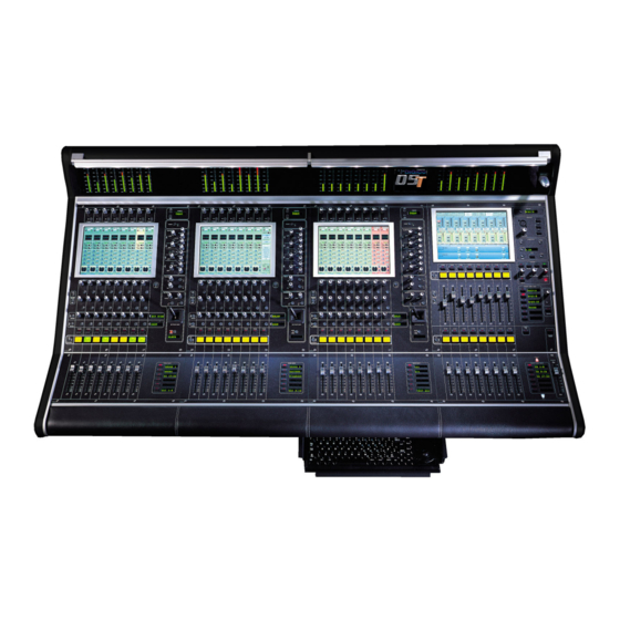
1.1 The Console The Digico D5T consists of a worksurface, and up to 4 Input/Output Rack Units. The Rack Units are connected to the console by optical fibre and/or MADI links, which carry all the audio input and output signals. -
Page 14: Hardware Configuration
Chapter 1 1.2 Hardware Configuration 1.2.1 Connections ................. Detailed information on the various systems of connection is provided in the Interconnection and System Setup Manual but the following diagram provides an overview of a single console setup. For Multiple Console Setups see Appendix B CONNECTION WITH MADI STAGE RACKS MAIN MADI IN... -
Page 15: The Digiconfig Program
Chapter 1 1.2.2 The DiGiConfig Program ............. The following example shows how to run the DiGiConfig program from the D5T software in order to configure you hardware: 1) Open the System / Service menu. 2) Press the Configure Hardware button, the D5T software will close and DiGiConfig will open. -
Page 16: Getting Started
Chapter 1 1.3 Getting Started Input Section Channel Meter Status Input Gain and Phase Channel Insert On / Off 4 Band Parametric EQ High and Low Pass Filters Aux / Pan / Dynamics Controls Dynamics Thresholds and On / Off Joystick Assignable Rotary and Switch Mute and Interactive LCD... - Page 17 Chapter 1 Input Channel Input Gain Phase Input Module Analogue Gain Digital Trim EQ Module Dynamics Module Aux Send & Compressor Controls Aux On/Off & Compressor Controls Screen Scroll Aux Send & Gate Controls Aux On/Off & Gate Controls Assigned Rotary Level Assign Rotary Assigned Button On/Off Assign Button...
-
Page 18: The New Session Panel
Chapter 1 1.3.1 The New Session Panel ............To create a new session, touch the Session Files button on the master screen and then touch the New Session button. The following panel will appear: The Main Buss Mode defines the format of the Main buss as Stereo, LCRS Surround or 5.1 Surround. This also affects the options for selecting the Sub Group and Aux buss formats: if the Main buss is stereo, the other busses cannot use the Surround formats, and if the main buss is Surround format, the other busses cannot use a different Surround format (although they can be stereo). -
Page 19: Selecting An Input Source
Chapter 1 If you have a system where more than one console is sharing the racks you may wish to use the Receive Only mode where the console will receive the rack’s existing settings but will not be able to control the gain on the racks. Options are: Isolate where the console will not communicate with the racks and therefore any adjustment of input gain or +48V switch will have no effect on the rack settings. - Page 20 Chapter 1 Input sources are divided into groups of signals eg. Stage 1-8 or Line 1-16. To select an input source: 1) Touch the top of the input screen to open the input panel. 2) Touch the name of the Signal Group to view the signal names. 3) Touch the name of the signal to assign it to the channel.
-
Page 21: Routing The Channel Signal
Chapter 1 1.3.4 Routing the Channel Signal ..........The channel signal can be routed to Sub Groups and Direct Outputs. To Route to a Sub Group: 1) Touch the bottom of the input screen to open the routing panel. 2) Touch the Sub Groups button if it is not already highlighted. 3) Touch the Sub Group button(s) that you require eg. -
Page 22: Routing Busses To Outputs
Chapter 1 1.3.5 Routing Busses To Outputs ..........The Master, Sub Group and Auxiliary busses may be routed to output sockets as part of the initial configuration. This is achieved by using the buss output routing panel in the Master Screen: 1) Touch the Buss Outputs button at the top of the master screen. -
Page 23: Matrix Inputs
Chapter 1 1.3.6 Matrix Inputs ................. The 32x32 way matrix is accessed by touching the Matrix Inputs button on the master screen or the Matrix button on the far right of the worksurface master section. Inputs are selected in the same way as the input channels (See Section 1.3.1). To route a Sub Group into the Matrix: 1) Touch the Matrix Inputs button on the master screen to open the panel. -
Page 24: Routing Matrix Groups To Outputs
Chapter 1 Worksurface controls are as follows: Trim Mute Solo Label Output Routing Delay Time Delay In/Out Compressor Threshold Compressor In/Out These channels provide Trim, Delay up to 510ms, Compression and 6 Band Parametric EQ. 1.3.8 Routing Matrix Groups To Outputs ........Matrix Group signals may be routed to a pre EQ, pre fader direct output and/or a post fader output To Route a Matrix Group to a post fader Output: 1) Touch the bottom of the matrix group screen to open the routing panel. - Page 25 Chapter 1 To Route a Matrix Group to a pre EQ, pre fader Direct Output: 1) Touch the bottom of the matrix group screen to open the routing panel. 2) Touch the Direct button if it is not already highlighted. 3) Touch the name of the Socket Group to view the output socket names.
-
Page 26: Save As New File
Chapter 1 1.3.9 Save As New File ..............When you change the configuration of the session you may save it to the console's flash drive under a new filename or simply overwrite the current file. To save under a new filename: 1) Touch the Session Files button at the top of the Master Screen to view the menu. -
Page 27: Dynamics
Chapter 1 1.3.11 EQ ..................The EQ section comprises four user-configurable parametric filters and a pair of swept High-pass and Low-pass filters. The EQ is accessed by touching the on screen display to Assign the channel (the colour changes to orange) and then using the controls on the right hand side of the input module. -
Page 28: Auxiliaries
Chapter 1 1.3.13 Auxiliaries ................The auxiliaries are accessed by touching the auxiliary row on screen or using the Screen Scroll buttons on the left of the input section. Aux Sends Aux On/Off and Pre/Post Screen Scroll Aux Sends Aux On/Off and Pre/Post Assign Rotary Assignable Rotary and Switch Labels with Value Readouts... -
Page 29: Control Groups
Chapter 1 1.3.14 Control Groups ..............Any number of input channels and output channels can be connected to one or more of the 24 Control Groups. They can then all be operated from a single worksurface control. Changes to the Control Group fader, mute or solo or controls will affect all channels con- nected to the group. -
Page 30: Master Fader Banks
Chapter 1 1.3.15 Master Fader Banks ............The faders in the console Master section control the output levels for busses, auxiliaries and the matrix. To select a bank, press the relevant Master Fader Bank button for the Upper faders. 1-20... -
Page 31: Monitoring
Chapter 1 1.3.16 Monitoring ................The Monitoring panel can be found under the Setup Menu on the Master Screen and some of the controls can be accessed on the right hand side of the Master worksurface. It may be accessed at any time to change the monitoring setup. Solo Safe Assign Solo 2 Level Clear All Solos... - Page 32 Chapter 2 Chapter 2 Inputs and Console Channels...
- Page 33 Chapter 2...
-
Page 34: The Input Channels
2.1.1 Channel Assignment ............The assignment of audio input channels to faders on the D5T worksurface is "soft", so that there is no direct link between channels and faders. The console can have up to 224 input sockets which are then assigned in blocks of eight to the console's physical fader banks. -
Page 35: Input Screen - The Standard View
Chapter 2 2.1.3 Input Screen - The Standard View ........In the screen's Standard View, each on-screen channel is shown in abbreviated form. The controls around the screen operate as follows: detailed information about each particular control is given later in this chapter. Upper row - Channel Input Gain and Phase. -
Page 36: Assigning A Channel
Chapter 2 2.1.5 Assigning a Channel ............To assign one of the on-screen channels so that you can adjust the EQ or Dynamics settings or use the Joystick, touch the on-screen display of the channel anywhere in the EQ or Dynamics area. (Not on the In / Out switches) The background colour of the channel changes to show that it is selected. -
Page 37: Input Module
Chapter 2 2.2.1 Input Module ................ You can display the Input Module for a fader by touching the top of the fader's on-screen channel strip, where the channel label is displayed. You can then hide the module by touching the same area again. Gain / Phase Signal Label Stereo Channel Mode Selector... - Page 38 Chapter 2 Processing for the right signal is taken from the highest numbered channel available which has no input route or insert return route selected. The channel which is used will no longer be available for normal operation. This is indicated by a white channel number. Stereo channels show all signal meters as pairs.
-
Page 39: Equaliser Module
Chapter 2 To Recall an existing channel preset, simply touch the preset you want. If the preset is not visible, you can touch the vertical arrows to scroll the list up or down. The preset settings are implemented in the channel as soon as you touch it. To store the current channel settings as a New preset, touch the New button, then type a name for the new preset. -
Page 40: Preset Selector
Chapter 2 Filter Centre Frequencies Response Graph Reset EQ Preset Selector Parametric 1 (Yellow) Curve Select for Parametric 1 Parametric 2 (Blue) EQ In/Out Parametric 3 (Green) Curve Select for Parametric 4 Parametric 4 (Red) Lopass In/Out Hipass / Lopass Filters Hipass In/Out When expanded, the EQ Module shows the filter settings in detail, using a different colour for each filter. -
Page 41: Dynamics Module
Chapter 2 2.2.3 Dynamics Module..............The Dynamics Module on each channel incorporates a Compressor and Gate, and also includes optional Filters for the sidechain and key signals. You can display the Dynamics Module by touching the dynamics display on the channel strip. Touching the In / Out buttons will switch the section On or Off. - Page 42 Chapter 2 The Key Solo places the Key Source signal on the Solo buss in PFL (Mono) mode. This is achieved by holding down the corresponding button in the gate controls below the screen. Configuration and Filters The default structure for the Dynamics Module is a simple Compressor-Gate layout, but you can also select from four other structures, or orders of effect processing, and use filters to achieve frequency-sensitive keying of the dynamics.
-
Page 43: Pan / Aux Module
Chapter 2 2.2.4 Pan / Aux Module ..............The Aux Send and Pan controls are always operated using the Lower Row of rotaries below each channel of the on-screen display. There are only two rotaries and switches for each channel, but these can be assigned to any Aux or Pan control using the Screen Scroll buttons at the left end or by touching the on-screen control that you wish to adjust. -
Page 44: Pan Control
Chapter 2 Pan Control Panning to the Master and Group busses is Stereo or Surround, depending on the console configuration. Pan position for each channel can be controlled in two ways: by using the rotary controls in the Lower Row below the on-screen channel display, or by Selecting the channel and using the Joystick. -
Page 45: Routing Module
Chapter 2 2.2.5 Routing Module ..............At the bottom of the input channel display is the Routing Module. This gives an abbreviated display of the current channel routing - on the left, the Master and Group routing, and on the right (if the channel is routed to a Direct Output) the name of the Direct Output socket. As the screen only has enough space to display one buss name, the routing of the channel to additional Groups is indicated by dots... -
Page 46: Direct Outputs
Chapter 2 SubGroup Routing When the SubGroups button is selected, the on-screen SubGroup buttons allow you to connect the channel to any number of output subgroup busses - mono subgroups are displayed with a single dot (SubGroups 1-4 in the diagram below), while stereo busses appear with a double dot (groups 5-8) and surround busses with a small box. - Page 47 Chapter 2 Insert Routing and On/Off Switch This button controls the routing for the input channel insert send and return selection. Touching the word Insert displays a panel which allows you to select Send and Return sockets in the same way as you would select an Input socket or a Direct output.
-
Page 48: The All Button
Chapter 2 2.2.6 The ALL Button ..............The All button provides a quick way of displaying all the Input, Aux or Routing modules for a bank of eight channels. If you hold down the All button while touching the Input, Routing or Aux modules, the expanded view of the relevant module is displayed for all the visible channels. - Page 49 Chapter 2 There is also an option to assign a channel by either touching its fader or pressing its solo button. To activate either of these functions: Press the Channel LCD Function button on the left of the input section and then press the Fader Assigns Channel and/or Solo Assigns Channel buttons.
- Page 50 Chapter 2 The Aux Send > Faders function allows you to control the Aux Send levels for a selected channel with the Upper and Lower Master Faders. 1) Press the Channel LCD Function button 2) Press the Aux Send > Faders button. 3) Press the Channel LCD buttons for the channel that you wish to control.
-
Page 51: Ganging
Chapter 2 2.3 Ganging Ganging is the linking of input channel controls which will allow most types of adjustment made to one channel within the gang to be automatically made to all of the other members. For example, if 2 channels are ganged and a fader movement is made on one of them, the other will be adjusted in the same way. Ganging can apply to any number of channels within one Input Bank. -
Page 52: Layout
Chapter 2 In a similar way, if one gang members group routing is changed, the other gang members will all be routed to the same group. NOTE: The following controls are not affected by changes to other gang members: Channel and Aux Pans Sub Feed Modes Input Phase buttons Solos... -
Page 53: Overview Setup
Chapter 2 2.4.2 Overview Setup ..............To change the appearance of the Overview screen touch the Layout button on the Master Screen and touch the Overview Setup button. This panel allows you to select which banks appear on the screen and whether they are Large or Small format. The default view shows Channel Banks and Master Banks in small format. -
Page 54: Master Banks
Chapter 2 To Clear a Channel Bank from a worksurface Fader Bank: 1) Touch the Clear Assignment button. 2) Press the Fader Bank button that you wish to clear. To assign a Channel bank to one of the console worksurface Fader Banks: 1) Touch the Channel Bank Assign button 2) Press the relevant Fader Bank button. -
Page 55: Move Channels
Chapter 2 2.4.5 Move Channels ..............Touching the Move Channels button in the Layout menu opens the Move Input Channels panel which allows a single channel or a range of channels to be moved. Touching a single channel allows it to be shuffled left or right with the arrows at the bottom of the panel. Both halves of a stereo linked pair are automatically selected together. -
Page 56: Duplicate Channel
Chapter 2 FAD=channel fader positions PAN = L/R and F/B pan or balance, Sub and Divergence levels and switches GRP = Group routing buttons only Channel mutes and control group membership are always included. Direct Outputs and Insert Sends can only be fed from one channel at a time and therefore their routing is not copied. Stereo channels will be copied as long as sufficient audio processing (unrouted channels) is available, otherwise they will appear as mono. -
Page 57: Channel Overview
Chapter 2 2.4.8 Channel Overview ..............The Channel Overview panel in the Layout menu provides similar functions to the Channel Banks panel and a graphic representation of all the consoles input channels. Many controls can be adjusted on screen using the mouse/trackball controls. The coloured outlines represent the banks that are currently being viewed on the worksurface and this view can be changed by touching the on screen banks. -
Page 58: Busses And Outputs
Chapter 3 Chapter 3 Busses and Outputs... - Page 59 Chapter 3...
-
Page 60: Buss Outputs Display
Chapter 3 3.1 Busses and Outputs 3.1.1 Buss Outputs Display ............The Master, Sub Group and Aux busses are displayed on the Master Screen, and the buss levels are controlled by the fader banks below the screen: The exact appearance of the screen depends on the console's current buss configuration, but the layout will look something like this: Scrolling the Master Screen If the console configuration is using more than the 24 outputs which the screen can display, you can "scroll"... -
Page 61: Expanding The Buss Output View
Chapter 3 3.1.2 Expanding the Buss Output View ........In the default state shown on the previous page, the level for each buss is controlled by a single fader, whether the buss is mono, stereo or surround. To see an expanded view of an assigned buss and access additional controls, touch the buss meter display. Touching the expanded view of the buss meter will restore the display back to the single-fader mode. -
Page 62: Label
Chapter 3 3.2.1 Label ..................The Label operates in the same way as an Input Channel label - to change it, just touch the on-screen label, then type a new name on the computer keyboard or the On Screen Touch Keyboard. When a buss is labelled its name will appear in the input channel routing display. -
Page 63: Level Trim
Chapter 3 3.2.3 Level Trim ................This trims the level for each buss signal. For Stereo or Surround busses, you can trim the level of each signal independently using the fader below the display. The faders can also be assigned to the Limiter controls (see below) - touch the Level Trim display to assign the fader to the Level control. -
Page 64: Buss Signals As Input Sources
Chapter 3 3.2.8 Buss Signals as Input Sources .......... The output results from output channels can be returned into input channels by scrolling to the bottom of the Signal Group listing at the input stage of a channel. You will see Signal Groups for each type of buss which is in the current console configuration (eg Mono, Stereo, LCRS etc) Touching the Signal Group buttons will show the separate legs of each buss and these signals can then be selected as inputs in the normal way. -
Page 65: The Matrix
Chapter 3 3.3 The Matrix 3.3.1 Matrix Inputs ................. The 32x32 way matrix is accessed by touching the Matrix Inputs button on the master screen or the Matrix button on the far right of the worksurface master section. Inputs are selected in the same way as the input channels (See Section 1.3.1). To route a Sub Group into the Matrix: 1) Touch the Matrix Inputs button on the master screen to open the panel. -
Page 66: Routing Matrix Groups To Outputs
Chapter 3 Worksurface controls are as follows: Trim Mute Solo Label Output Routing Delay Time Delay In/Out Compressor Threshold Compressor In/Out These channels provide Trim, Delay up to 510ms, Compression and 6 Band Parametric EQ. 3.3.3 Routing Matrix Groups To Outputs ........Matrix Group signals may be routed to a pre EQ, pre fader direct output and/or a post fader output To Route a Matrix Group to a post fader Output: 1) Touch the bottom of the matrix group screen to open the routing panel. - Page 67 Chapter 3 To Route a Matrix Group to a pre EQ, pre fader Direct Output: 1) Touch the bottom of the matrix group screen to open the routing panel. 2) Touch the Direct button if it is not already highlighted. 3) Touch the name of the Socket Group to view the output socket names.
-
Page 68: Master Section
Chapter 4 Chapter 4 Master Section... - Page 69 Chapter 4...
-
Page 70: The Master Screen
Chapter 4 4.1 Master Section The Master section of the D5T console includes the output controls described in the previous chapter and the meter bridge above it: Meter Status Talkback Master Screen Cues Mute and Interactive LCD Monitoring Function Button... -
Page 71: The Menu Buttons
This command should be used to shut down the console in normal operation. Quit To Windows Command In the Service menu, this button will close the D5T program but will remain in a Windows environment. It is unlikely that the user will need this option in normal operation. -
Page 72: Console Security
Chapter 4 4.1.3 Console Security ..............The console has 3 modes of operation which dictate the types of operations that can be performed. The Setup mode is essential if you wish to access all the console operations but when the basic setup is complete you may wish to switch to Live mode which only enables changes to controllers and not routing, reconfiguring or labelling. -
Page 73: Configuring The Console
4.2 Configuring the Console As a digital console, the D5T is highly configurable, allowing a wide range of different bussing formats and channel configurations. This section describes how to use the command buttons on the Master Screen to Configure, store and recall sessions. -
Page 74: Clearing Settings
Chapter 4 4.2.3 Clearing Settings ..............When you start a new session all current settings will be inherited by default but the Mix Automation and Cue List will be cleared. The buttons at the bottom of the New Session panel allow you to clear settings according to your own requirements. When the buttons are pressed, the relevant settings will be cleared. -
Page 75: The Save As New File Button
Chapter 4 4.2.5 The Save As New File Button ..........Touching this button will open the following panel. This panel allows sessions to be saved as new files under new names. Select your drive and folder by touching in the boxes in the bottom left corner, then touch and type a new file name (with a maximum of 8 letters and no punctuation) in the box on the top left. -
Page 76: Monitoring
Chapter 4 Select a drive and folder in the bottom left hand corner of the panel, type a new name in the New Filename box and press the Save button. NOTE: The current presets file is always saved automatically when the console is shut down 4.2.9 Monitoring ................ - Page 77 Chapter 4 There are two solo busses and each console solo button can be independently assigned to use Solo 1 or Solo 2. Output solos may use a total of 16 inputs to each solo buss. Therefore, if the console was being used for stage monitors, the first solo buss could feed an "in ear" monitor and the second solo buss could feed a wedge.
-
Page 78: Master Section Meters
Chapter 4 Monitor Mute Touch the Mute button to cut the monitor signal. Solo Clear Pressing the Solo Clear button will ensure that there are no solos engaged anywhere on the console. Solo Trim Level The Solo Level may be adjusted by altering the dB value in the Trim Level box. If the worksurface "Solo Trim" control is adjusted, this panel will automatically appear and the Trim Level value will change to reflect any adjustment. -
Page 79: Meter Ballistics
In the unlikely event of a console software crash, an abnormal shutdown, hardware or power failure, D5T will recover the latest session automatically and it can be rebooted without losing audio. If there is any problem with this process, holding the keyboard Shift Key during the reloading of D5T software will open the following panel: IMPORTANT NOTE: The easiest method of doing this is to Quit To Windows and then reload D5T software from there. -
Page 80: Talkback Configuration Button
Chapter 4 4.3.1 Talkback Configuration Button .......... The two talkback channels can be mixed independently onto any buss using the Talkback Setup panel, which is displayed on the Master screen when the on-screen Talkback button is touched. When you first touch the on-screen Talkback button, only the bottom section of the panel is displayed - push the Talkback Setup button to display the full mixer panel. -
Page 81: The Talkback Mixer
Chapter 4 4.3.3 The Talkback Mixer .............. Each output buss has its own level control in the Talkback mixer, along with a switch for connecting each Talkback channel to the buss at the chosen level. The level controls can be adjusted using the faders below the screen, with each row of busses assigned to the physical faders by touching one of the rows of faders in the display. -
Page 82: Naming Control Groups
Chapter 4 A list of all the connected channels and their names is displayed above each Control Group display, touch the area above the Clear button to expand this list. When a fader is touched it is highlighted in the list. You can also clear all the channels from a Control Group by pressing Clear. -
Page 83: Master Lcd Function Buttons
Chapter 4 4.5 Master LCD Function Buttons Pressing the Master LCD Function button on the left hand side of the Master Section allows you to select the function that the individual Master LCD Buttons are currently assigned to. To Show Functions Press the Master LCD Function button. - Page 84 Chapter 4 Auxiliary sends can be controlled by the console's channel faders or rotaries in several different ways. There are Assign Sends To Faders and Assign Sends To Rotaries buttons in the Auxiliary Buss Control panel (See Section 3.2.2 - Buss Control Button) which activate these functions but for faster access there are options to activate them by a Solo Press on the Auxiliary Masters.
- Page 85 Chapter 4 The contents of a Master Fader Bank can be customised at any time by adding or removing faders from it. To Assign Faders To Banks 1) Press the Master LCD Function button for the relevant bank. 2) Press the Assign Faders button. 3) Press the Master LCD button for the Master fader that you wish to use.
- Page 86 Chapter 4 To Unassign Faders From Banks 1) Press the Master LCD Function button for the relevant bank. 2) Press the Unassign Faders button. 3) Press the Master LCD buttons for the fader(s) that you wish to Unassign. 4) Press the Master LCD Function button to exit Unassign Faders mode. 5) Press the Solo function button to return to the standard view.
- Page 87 Chapter 4 Master Fader Banks can also be built from scratch in the following way: To Build A Bank 1) Press the Master Fader Bank button for the bank that you wish to build. 2) Press the Master LCD Function button for the relevant bank. 3) Press the Build Bank button.
-
Page 88: Transport / Timecode Configuration
4.7 Transport / Timecode Configuration When the D5T is used in typical live sound applications there will be no time related control systems (timecode) or motion control (tape transport) connected. Synchronisation and machine control does not need to be considered. -
Page 89: Audio Synchronisation
If you are only using MADI connections, Master must be selected as the Audio Sync source. When the D5T is used with only analogue signals connected to both inputs and outputs synchronisation does not need to be considered. -
Page 90: External Sync Sources
Please note the Digico's experience shows by far the most trouble free master sync source will be an AES/EBU signal (from the AES sync input or audio input). Word clock is second best and video is the more difficult source to implement. - Page 91 Chapter 5 Chapter 5 The Cue List...
- Page 92 Chapter 5...
-
Page 93: Cue List
Chapter 5 5.1 Cue List Any number of Cues containing the entire current console settings can be stored and recalled using the Cue List panel. (This is only limited by system memory) These Cues can be absolute or relative to another cue. The scope of the cue can be set by controller type or by input channel. -
Page 94: Normal, Master And Relative Cues
Chapter 5 5.1.1 Normal, Master and Relative Cues ........There are three types of Cue: 1) NORMAL CUE - this appears in black on the list and is always followed by another NORMAL CUE or MASTER CUE. 2) MASTER CUE - this appears in black on the list and is always followed by a RELATIVE CUE. 3) RELATIVE CUE - this appears in red on the list and it's entry is indented. -
Page 95: Replacing A Cue
Chapter 5 5.1.4 Replacing a Cue ..............To update or change a cue, set the console controls as required and then touch the Replace button followed by the cue that you wish to amend. A dialogue box will appear asking you to confirm the action. There is also a button with an option to Replace Current cue and this can be used to replace the last cue that was fired. -
Page 96: Moving A Cue
Chapter 5 A change in any of the following settings can be copied to all selected cues in edit mode: Snapshottable controllers Routing Relay outputs Selection of MIDI Patches Crossfade times Control Group members Gang members All Channels and Exclude buttons in Channel Scope NOTE: Banks (Layout) settings are excluded from the Edit operation, since it is likely that scrolling, etc. -
Page 97: The Cue Scope Editor
Chapter 5 5.1.12 The Cue Scope Editor ............Pressing the Scope button expands the panel to display and edit the scope for one cue, indicated by a light band linking the cue list to the scope. The scroll buttons in the centre of the panel move the scope editing up and down the cue list. If the Preview button is pressed the scope for the next cue in the list is displayed. -
Page 98: Cue Timing
Chapter 5 Fader banks currently assigned to input surfaces but not the names of these banks. Which channel on each surface is assigned to EQ/Dynamics/Joystick controls. Which rows of pans or auxes are assigned to rotaries. The Master Fader Banks assignment. Note: Banks are not intended to reproduce the exact screen states. -
Page 99: Cues And Midi
5.1.17 MIDI Patches ............... The console's main MIDI port is known as MIDI port T. If your D5T is fitted with the combination MIDI/GPI/GPO card it can also have 2 more MIDI ports A & B (Each card provides 16 extra MIDI channels - A1 to A16 on the first card and B1 to B16 on the second card.) The port letter may be prefixed on any line of the MIDI Patches Editor before the MIDI channel number (separated by spaces). -
Page 100: Live Update
Chapter 5 Note Off The MIDI Port Number (Port T is assumed if there is no entry here) A 2 digit MIDI Channel number between 01 and 16 N- to indicate Note Off A note number between 0 and 127 A velocity off value between 0 and 127 Program Change The MIDI Port Number (Port T is assumed if there is no entry here) - Page 101 Chapter 5 In a similar way, if a channel has a microphone as an input source and the microphone is always used by the same actor, it may be that thingssuch as costume changes will require different settings for that channel during the course of the show. So a channel could be called "Harry"...
-
Page 102: Fader Examples
Chapter 5 5) The Current Cue Type As explained at the start of this chapter, there are 3 different cue types - Normal, Master and Relative . The updating of cues may differ according to which type is current at the time. This rule only applies to faders as other controllers will all be updated irrespective of the type of the current cue assuming that the control in question meets the other criteria. -
Page 103: Other Db Controller Examples
Chapter 5 5.2.2 Other dB Controller Examples ..........eg Auxiliary Sends, Channel Gains and other controllers that are measured in dBs With Option OFF 1) Current Cue is a Normal Cue and an auxiliary send in a channel which has the same name in all cues is adjusted. Result: All cues are updated with the auxiliary change if their setting was the same as the original cue's setting. -
Page 104: Cue Editor Software
It requires a Windows PC running Windows 98 (or later) software or a Mac running Windows emulation software. The program can be run as a standalone application or it can be mirrored to the D5T to make changes to the Cue List in real time. -
Page 105: Input Channels And Sets
Chapter 5 5.3.3 Input Channels and Sets ............. The small microphone icon represents the Input Channel list. In this window, input channels can be named and assigned to sets and aliases can be created. To name a channel, left click in the Current Name box for the required channel and type a name. To create an alias, right click in the Current Name box for the required channel and select Add Alias. -
Page 106: Cue List
Although the Cue Notes and Scope are shown in this window, they cannot be edited here. Scope can only be seen as a colour coded dots with a key at the bottom of the window and must be edited on the D5T, D5TC or a remote computer running D5T software. -
Page 107: Cue Notes
Chapter 5 5.3.5 Cue Notes ................The icon labelled Notes will open the Cue Notes window and then you can type directly into the text box. Once the window is open, the selection of a cue from the list will automatically display the relevant notes. Right clicking in this window will show the standard options for Undo/Cut/Copy/Paste/Delete and Select All. -
Page 108: Relays
Left or right clicking in the box for a specific relay number in a cue will scroll through the three options available. It is far simpler to program relays in the Cue Editor than in the Cue List on the D5T and it is not currently possible to program a pulse using the D5T at all. -
Page 109: Midi Program Changes
Chapter 5 5.3.9 MIDI Program Changes ............The icon showing a MIDI socket and a small horizontal grid represents MIDI Program Changes. If the MIDI Channel names have been set up as described above then scrolling the window horizontally will show column names for each MIDI device in the system. -
Page 110: Machine Control
Chapter 5 5.3.11 Machine Control ..............The icon showing two green arrows represents Machine Control Messages. Each cue can send combinations of Play From, Play To and Locate To commands. The simplest method of inserting these commands into a cue is to right click on the cue's row and select the required command from the drop down menu. - Page 111 Chapter 6 Chapter 6 Automation...
-
Page 112: Real Time Automation
6.1 Real Time Automation D5T's automation system can record and play back the movements of most of the console's channel or buss controls. Real Time Automation operates while timecode is running, and allows you to record the adjustments you make while listening to the audio. -
Page 113: Play (Update) Mode
Chapter 6 6.1.4 Play (Update) Mode .............. When a channel's Play Button is lit and its Record Button is not lit, the channel is in Play mode - if Touch Record is switched on in the Automation Options this is also the mode used for updating the automated controls changes. You can put a channel into Play mode by pressing the Play button. -
Page 114: Safe Mode (Dynamic Automation)
Chapter 6 Manual Nulling You can decide to control the rate at which a particular channel nulls back to the old automation even when auto-null is operating. To do this, touch-record a fader to start recording. When you are ready to return to play release the fader. The Play LED will start to flash to indicate that it is nulling - grab it again. -
Page 115: Edit Block
Chapter 6 If the Only Plays button is pressed the offset will only be applied to controls which are in play mode. If the Exclude Safes button is pressed the offset will not apply to controls which have been made safe in the Automation Editor. Note: If events are moved backwards past time zero they are deleted. -
Page 116: Trim Block
Chapter 6 6.1.9 Trim Block ................Pressing the Trim Block button in the Automation menu opens the following panel. This allows a trim offset to be applied to any or all automated faders without changing the automation data. The trim can be auditioned and refined as long as the panel remains open, and then applied to the automation data for a single channel or all selected channels by timecode range to make it permanent. -
Page 117: Cue Automation
Chapter 6 6.1.10 Cue Automation ..............The cues can be integrated into the automation system to allow control of non-dynamically automated parameters, or simply to allow instant changes for the entire console which are all tied to a single editable event. For more information on how to store and recall cues see section 5.1. -
Page 118: Midi Patches
Chapter 6 Remember that automation modes can be set on a channel and on an individual parameter basis, as described in the third example above. For example, it is possible to set all a channel's controls except faders to Update, and then control the channel fader by firing a cue. Even a single band of a particular EQ section could be taken out of dynamic automation and put under cue control. -
Page 119: Scaling The Automation Editor Display
Chapter 6 Channel Status Indicators To the right of any channel or section name are three status indicators, indicating the automation mode in which that channel is currently operating. These are also buttons, and you can press them to set the relevant mode. The third button is used to select Safe Mode - see Safe Mode, section 6.1.6. -
Page 120: The Time-Line
Chapter 6 6.2.3 The Time-Line ..............The Time-Line indicates the current time, as displayed on the timecode display. The timecode position of the trackball pointer is shown at the bottom left of the Automation Editor screen. Time-Line Trackball Position When timecode is running, you can choose to make the time-line move with it, so that the line travels from left to right: see Following the Timecode overleaf. - Page 121 Chapter 6 Fader Changes and Mute On/Off Events For each channel, the Automation Editor shows the fader position and Mute status as follows: Areas which are coloured red are Muted, and areas which are coloured blue are un-Muted. Each change in the height of the blue/red area represents a fader movement.
-
Page 122: Automation Mode Buttons
Chapter 6 EQ Events The three parameters for all 4 bands of the EQ are shown under this drop-down display, with the HF at the top: The frequency range of each band is indicated. The Gain of the HF is followed by the words in/out. This line indicates the automation of the entire EQ circuit being switched in and out. -
Page 123: Selecting And Editing Events
Chapter 6 Global Safe Safe Scope Buttons Global Safe Button Inputs Safe Button Channel Safe Button Above the column of Rec/Play/Safe switches there is a Global Safe button. Pressing this will make all the controllers on all the console channels safe if they are included in the Safe Scope. The safe button next to each console section name (eg Inputs) will perform a similar function on the controllers and channels in that section. - Page 124 Chapter 6 Events are highlighted to show that they are selected, and an outline box appears around the outside of a selected group. To de-select individual events within a selected group, hold down the <Ctrl> key while clicking on the event. Switch events are: •...
-
Page 125: The Editing Tools
Chapter 6 6.2.8 The Editing Tools ..............These tools operate only on the Selected events. They are greyed out until you have used the Selector tools to select one or more events. Delete This button simply deletes all the selected events from the mix. They cannot be recovered, except by using the UNDO button - see below. Cut, Copy and Paste These buttons use the Clipboard for temporary storage of events. -
Page 126: Write To Start And Write To End
Chapter 6 Join Levels "Joining" two levels together means fading from one to the other smoothly over a period of time. The Join tool works like the Fade-Out tool - you choose which levels to Join by "dragging" the tool from one screen position to another. The Join affects all the lines over which you drag the tool. - Page 127 Chapter 7 Chapter 7 Effects...
- Page 128 Chapter 7...
-
Page 129: Configure Effects
Chapter 7 7.1 Configure Effects If The Effects module is not active, touch Setup / Service / Configure Hardware button to open the DiGiConfig program, select the console that you want to configure by pressing the relevant This button, then tick the relevant boxes at the top of the panel and press OK. The optional effects section provides up to 6 different effects modules. -
Page 130: Effects And Routing
Chapter 7 7.1.2 Effects and Routing ............. Signals can be routed to the effects modules from Direct Outputs, Insert Sends, Auxiliary Outputs and SubGroup Outputs. An output routing Socket Group named Effects which contains the list of all the effects modules' inputs appears in the output socket routing panel. In a similar way, the returns from the effects modules appear in a signal group named Effects in the input socket routing panel. -
Page 131: Output Insert
Chapter 7 The output of the Reverb module must then be monitored in a channel by opening the input routing screen, selecting the Effects signal group and then selecting Reverb L from the signal list. Touch the Stereo button to monitor Reverb L and Reverb R in the same channel. From Effects 7.1.4 Output Insert ................ -
Page 132: Effects Control
Chapter 7 7.2 Effects Control 7.2.1 Effects Parameters ............... Touching the Effects button in the Master Screen opens the following panel: Touch the tabs at the top of the panel to select the effect that you wish to adjust. Normally, two effects modules are shown in the panel but the output processing module uses the whole panel on its own. - Page 133 Chapter 7 Main Channels Dynamics Provides Crossover adjustment, 3 band compression and Limiting. Click here to view Click here to change Click here to view Processing In/Out Threshold parameter view Limiter Attack Threshold or Release Release Ratio Main EQ Provides 4 Band EQ with adjustable Filter Types on Bands 1 and 4. Click here to change Set EQ Flat Click here to change...
- Page 134 Chapter 7 Graphic EQ The controls for the 12 Graphic EQs are as follows: Click here to link EQs in stereo pairs Reset Flat Touch faders on screen Click here to select Processing In/Out to assign control to which Graphic EQ Trim Control to adjust (1 of 6) worksurface master...
- Page 135 Chapter 8 Chapter 8 Troubleshooting...
- Page 136 Chapter 8...
- Page 137 Chapter 8 8.1 Troubleshooting If you are experiencing any difficulty with D5T operation, please check the following commonly asked questions and answers. If any users would like to contribute to this section of the manual please send the details of your questions to support@digiconsoles.com.
- Page 138 Note: If you hold the Shift key while Windows is rebooting the Surfaces.exe program will not start and the console will not function correctly. Therefore, load the D5T software then Quit To Windows using the System / Service Menu and then load the D5T software again whilst holding the Shift key.
- Page 139 Appendix A Appendix A D5TC (Theatre Masters Controller)
- Page 140 Appendix A...
-
Page 141: Appendix A - The Theatre Masters Controller
This appendix should be read in conjunction with the D5T User manual as many of its functions simply provide a remote control interface to the D5T itself. The TC screen is almost exactly the same as the D5T Master Screen with the exception of the Macro functions. -
Page 142: A.2 Connection And Setup
A.2 Connection and Setup ............The D5TC is connected to the D5T using a CAT5 Ethernet cable. If these are the only two devices in the system an Ethernet crossed cable can be directly connected to both but if there is another remote controller, a remote PC running the D5T Cue Editor or a D5T Redundant Engine in the system then all of these devices should be connected via an Ethernet switch using standard CAT5 cables. -
Page 143: A.4 Sync Session
Select here to update the sockets file This shows a list of the devices that are connected on the network and in this example there is a D5T, its Redundant Engine and the Theatre Masters Controller (D5TC). 1) Select the device from the list that you wish to transfer from (the D5T in this example). -
Page 144: A.6 Masters
The Undo button will undo the action of the last cue fired but only if the Enable Undo button is active in the on screen cue list. The Fire Now button duplicates the Fire button on the D5T main worksurface - You can select a cue to fire by scrolling through the list of... -
Page 145: A.8 Global Safe And Mute Buttons
All Sub Groups. All Matrix outs. The switch and rotary controls situated next to the Mute All buttons duplicate the D5T main worksurface Touch and Turn controls and can be used to control Matrix sends and Effects parameters. A.9 Macros .................. - Page 146 2) Type the messages with the correct syntax directly into the ON and/or OFF text boxes. The most common examples are shown at the top of the panel. A full list of these messages can be found in the file called D5Setup.rtf in the console's D5T or D5TC directory.
- Page 147 Appendix B Appendix B Multiple Console Setups (Inc. Redundant Engines)
- Page 148 Appendix B...
-
Page 149: Appendix B - Multiple Console Setups
MAIN LOCAL RACK To set up the hardware configuration open the DiGiConfig program in the System / Service / Configure Hardware menu. D5T software will automatically close to enable configuration changes. Select all the consoles in the rig (FOH Main and MON Main) and then select the console that you are configuring by pressing the THIS ONE? button. - Page 150 Appendix B The following configuration details will have been created: FOH Console Details Monitor Console Details Note that the Optocore IDs are 20 (FOH) and 22 (MON) and the IP addresses must be unique. In this example, other details are the same but this is not necessarily always the case.
-
Page 151: B.1.2 Gain Tracking Settings
Appendix B B.1.2 Gain Tracking Settings ............With the Optocore connection, Gain Tracking can be bidirectional. If either console adjusts the analogue gain, the other console can compensate for that change by applying an opposite digital trim. Each Input Channel has a Track On/Off switch next to the Digital Trim control. -
Page 152: B.1.3 Gain Tracking Procedures
Appendix B B.1.3 Gain Tracking Procedures ..........The suggested setup for two consoles which are sharing the same racks is as follows: a) One operator will be responsible for adjusting the analogue gains on the racks (Recommended): 1) One console should fully connect to the racks using the System / Consoles and Racks panel's Full Connect button for the Optocore racks. -
Page 153: B.2.1 Redundant Optical Loop
Ethernet switch if some form of Remote control is used with the system. This could be a Remote PC running the console software, the D5T Cue Editor, a D5TC (Theatre Masters Controller) or a standard D5(T) RC (Remote Controller). -
Page 154: B.2.3 Digiconfig – Hardware Configuration
Appendix B Optical connections should be: Stage Rack 1 Opto A to Stage Rack 2 Opto B. Stage Rack 2 Opto A to Redundant Engine Opto B. Redundant Engine Opto A to Main Console Opto B. Main Console Opto A back to Stage Rack Opto B if a Redundant Optical Loop is required. MADI connections with the Local Racks should be: Main Console MADI 2 OUT to Local Rack MADI A IN. -
Page 155: B.2.4 Consoles And Racks Panel
Appendix B There are several significant things to note in the above Console Configuration panels. 1) As these panels represent the Main console and its Redundant Engine, the configurations should be identical in most repects. NOTE: The hardware configurations will not differ as although the Redundant Engine doesn't actually have a worksurface, it behaves as if it has and therefore on earlier models of RE the Worksurface warning light on the Master Screen will appear to show an red error light. -
Page 156: B.2.5 Sync Session
Select here to update the sockets file This shows a list of the devices that are connected on the network and in this example there is a D5T, its Redundant Engine and the Theatre Masters Controller (D5TC). 1) Select the device from the list that you wish to transfer from (the D5T in this example). -
Page 157: B.2.7 Digirack Control
Appendix B 1) Select the device from the list that you wish to Mirror from (the D5T in this example). 2) Select FROM other console and Mirror Now and then press OK. When the process is complete, the MIRRORED Button will be highlighted in orange as seen below. There will also be a pop up message to confirm that mirroring has taken place. -
Page 158: B.2.8 Normal Operation
Appendix B B.2.8 Normal Operation ..............When the system has been completely configured, a failure in the console’s audio engine will result in an automatic switch to the Redun- dant Engine. The Master Audio Outputs Active button on the Redundant engine will be highlighted in orange and will continue to process the audio until the operator chooses to switch back to the Main console engine. - Page 159 Appendix B The following diagram shows the connections required to set up a mirror console with MADI connections: MIRROR CONSOLES USING MADI (Same setup as a console and a Redundant Engine) STAGE RACKS MAIN MAIN MADI MADI WORD CLOCK ETHERNET CROSSOVER CABLE PORT 1...
- Page 160 Appendix B The following diagram shows the connections required to set up a full rig with redundant mirror Front of House and Monitor consoles, a redundant optical loop and multi-operator Gain Tracking. MADI available for independent feeds for broadcast, recording etc STAGE RACKS ID=30 ID=32...
-
Page 161: B.3.1 Pc Remote Control
B.3.1 PC Remote Control .............. If D5T software is run on a standalone PC or laptop, sessions may be prepared off line or the PC can be used to remote control a console. Input channel windows are run in separate moveable windows for easier access on smaller screens. The Overview Screen and a Bank Switches window are also displayed. - Page 162 Appendix B Standalone PC Screen Appearance B-16...
- Page 163 Index Index Symbols Clear Assignment 2-23 Clear Track 6-16 3 band compression 7-7 Clearing Settings 4-7 9-pin 4-21 Close Gap 6-5 9-pin Eavesdrop 4-21 Compressor 2-10 Configure Effects 7-3 Connect All 3-5 AES/EBU 4-23 Console Security 1-8, 4-5 AFL 4-10 Consoles &...
- Page 164 Index Ethernet Connected 1-8 Event Display 6-10 Label 3-5 Event Tools 6-15 Layout 2-21 Exclude 5-7 Leave Gap 6-5 Exclude Safes 6-5 Level Events 6-14 External Screens 2-21 Level Trim 3-6 External Sync 4-22, 4-23 Limiter 3-6 Limiter In/Out 3-3 Limiting 7-7 Fade-Out (Automation) 6-15 Listen to Copied MADI 4-5...
- Page 165 Index Note Off 5-10 Round to whole dBs 4-4 Note On 5-9 Route to a Direct Output 1-11, 1-14, 1-15, 3- Nudge Back / Forward 6-15 9, 3-10 Route to a Group 1-11 Routing 2-14 Off-line 4-21 Routing Busses To Outputs 1-12 Offset 6-4 On Screen Touch Keyboard 4-4 Only Display Name 2-18...
- Page 166 Index Switch events 6-14 Switch Rec to Play On Stop 6-3 Synchronisation Digital 4-22 System Menu 4-4 System Options 4-4 System Shut Down 4-4 System Status Indicators 4-4 Talkback 4-12 Talkback Mic 4-13 Talkback Mixer 4-14 Talkback Presets 4-14 Talkback Setup 4-13 The Option Button 5-11 Time-Line 6-10 Timecode Output 4-21...
Need help?
Do you have a question about the D5T and is the answer not in the manual?
Questions and answers