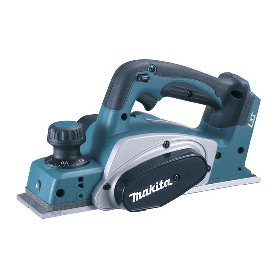
Makita BKP140 Technical Information
14.4v cordless planer 82mm (3-1/4")
Hide thumbs
Also See for BKP140:
- Instruction manual (64 pages) ,
- Instruction manual (17 pages) ,
- Instruction manual (32 pages)
Advertisement
Quick Links
T
ECHNICAL INFORMATION
Model No.
Description
C
ONCEPT AND MAIN APPLICATIONS
Model BKP140 is a 14.4V 82mm Cordless Planer developed
with the same advantages of our AC power planer Model KP0800.
Battery BL1415 is not compatible with this model.
BKP140 is available in the following variations.
Model No.
BKP140Z
BKP140RF
BKP140RFE
S
pecification
Specifications
Battery BL1430
No load speed: rpm= min.
Capacities: mm (")
Electric brake
Weight according to
EPTA-Procedure 01/2003*: kg (lbs)
*with Battery BL1430, Planer blade 82 and Dust nozzle
S
tandard equipment
Planer blade (re-sharpenable type) or T.C.T. Mini planer blade (disposable type) ........ 1
Sharpening holder assembly (for countries using re-sharpenable type Planer blade) .... 1
Dressing stone (for countries using re-sharpenable type Planer blade) .......................... 1
Blade gauge assembly ..................................................................................................... 1
Socket wrench 9 .............................................................................................................. 1
Guide rule ........................................................................................................................ 1
Dust nozzle ...................................................................................................................... 1
Plastic carrying case (except for BKP140Z) ................................................................... 1
Note: The standard equipment for the tool shown above may vary by country.
O
ptional accessories
Fast charger DC18RA
Charger DC18SD
Automotive charger DC18SE
Charger DC24SC
Li-ion battery BL1430
Li-ion battery BL1430A
Dust bag
BKP140
14.4V Cordless Planer 82mm (3-1/4
Battery
Charger
Type
Quantity
No
No
DC18RA
BL1430
DC18RA
BL1430
Model
Voltage: V
Capacity: Ah
Cell
-1
Planing width
Planing depth
Shiplapping
Planer blade (re-sharpenable type, disposable type)
Guide rule
Blade gauge assembly
Dust nozzle
Dressing stone
Elbow
)
"
Battery
cover
No
No
1
No
2
1
BKP140
14.4
3.0
Li-ion
13,000
82 (3-1/4)
1.6 (1/16)
9 (11/32)
Yes
3.2 (7.2)
PRODUCT
P 1/ 10
W
L
Dimensions: mm (")
Length (L)
329 (13)
Width (W)
157 (6-3/16)
Height (H)
160 (6-5/16)
H
Advertisement

Related Manuals for Makita BKP140


Summary of Contents for Makita BKP140
- Page 1 14.4V Cordless Planer 82mm (3-1/4 " ONCEPT AND MAIN APPLICATIONS Model BKP140 is a 14.4V 82mm Cordless Planer developed with the same advantages of our AC power planer Model KP0800. Battery BL1415 is not compatible with this model. BKP140 is available in the following variations.
-
Page 2: Necessary Repairing Tools
Apply the following lubricants to protect parts and product from unusual abrasion. Item No. Description Portion to lubricate Lubricant Amount Cam plate Surface where Knob contacts Makita grease N No.2 a little (a) Threaded portion VG100 Front base (b) Cylindrical portion where Main frame contacts Fig. 1 Knob cover... - Page 3 P 3/ 10 epair [3] DISASSEMBLY/ASSEMBLY [3]-1. Poly V-Belt 4-241 DISASSEMBLING Disassemble Poly V-belt 4-241. (Fig. 2) Fig. 2 1. Remove M4x16 Pan head screw 2. Cut Poly V-belt 4-241 with Nippers and separate Belt cover from when it has damage. Main frame complete.
- Page 4 P 4/ 10 epair [3] DISASSEMBLY/ASSEMBLY [3]-2. Motor section DISASSEMBLING (1) Remove Poly V-belt 4-241. (Refer to Fig. 2) (2) Separate Bracket section from Main frame complete. (Fig. 5) Fig. 5 1. Remove Carbon brushes. 2. Remove four 4x18 Tapping screws. 3.
- Page 5 P 5/ 10 epair [3] DISASSEMBLY/ASSEMBLY [3]-2. Motor section (cont.) DISASSEMBLING (4) Remove Yoke unit. (Fig. 7) Fig. 7 8. Remove Baffle plate. 9. Remove Yoke unit by tapping Main frame complete with Plastic hammer. Main frame Baffle plate Yoke unit complete ASSEMBLING (1) Assemble Yoke unit to Main frame complete.
- Page 6 P 6/ 10 epair [3] DISASSEMBLY/ASSEMBLY [3]-3. Drum DISASSEMBLING (1) Disassemble Bracket (with Armature, Drum). (Refer to Figs. 2 and 5) (2) Set Phillips bit and Bit adapter to Impact driver in order to remove V-pulley 4-33.5. (Refer to Fig. 6) (3) Disassemble Drum from Bracket.
- Page 7 P 7/ 10 epair [3] DISASSEMBLY/ASSEMBLY [3]-4. Front Base, Base, Foot DISASSEMBLING Disassemble Front base and Base (rear side). (Fig. 11) Fig. 11 1. Remove Knob cover by levering up 2. Remove Retaining ring S-8 3. Use Knob cover as a socket wrench with 1R263 inserted into the gap with 1R004 or 1R291.
- Page 8 P 8/ 10 epair [3] DISASSEMBLY/ASSEMBLY [3]-4. Front Base, Base, Foot (cont.) ASSEMBLING (1) Assemble Foot to Base (rear) before assembling Base to Main frame. (Fig. 12) Assemble Base with Foot to Main frame by taking the disassembling step in reverse. (Refer to Fig. 11) Fig.
-
Page 9: Circuit Diagram
P 9/ 10 ircuit diagram Fig. D-1 Color index of lead wires' sheath Black White Yellow Switch *Line filter Brush holder A Motor Housing Controller Terminal Brush holder B *Line filter is not used for some countries. iring diagram Fig. D-2 Wiring of Brush Holder's Lead Wire Motor housing viewed Motor housing, viewed... - Page 10 P 10/ 10 iring diagram Fig. D-3 Wiring to Terminal Wire connecting portions The Flag connectors have to be connected so that their wire connecting portions are located over the mark of + - poles. Fig. D-4 Wiring in Main frame Put Lead wires into Lead wire holders.
Need help?
Do you have a question about the BKP140 and is the answer not in the manual?
Questions and answers