Table of Contents
Advertisement
Quick Links
Advertisement
Table of Contents

Related Manuals for Efka AB620A5035


Summary of Contents for Efka AB620A5035
- Page 1 CONTROL AB620A5035 Operating manual With parameter list - Putting into Service - Settings - Functional Description - Connection Diagrams - Timing Diagrams No. 402446 English FRANKL & KIRCHNER EFKA OF AMERICA INC. EFKA SINGAPORE PTE. LTD. GMBH & CO KG...
- Page 2 They may differ from those in your display. For current versions of the Instructions for Use and Lists of Parameters, necessary for operating EFKA drives in accordance with regulations, please refer to the EFKA web site www.efka.net, page “Downloads”.
-
Page 3: Table Of Contents
- AB620A5035 CONTENTS Page 1 Range of Applications Use in Accordance with Regulations 2 Scope of Supply Special Accessories 2.1.1 Adapter Cords for Special Machines 3 Putting into Service 4 Setting and Putting into Service with the Aid of the Fast Installation Routine (SIR) - Page 4 - AB620A5035 7.4.5 Single Start Backtack / Start Stitch Condensing End Backtack / End Stitch Condensing 7.5.1 Speed n4 at the Seam End 7.5.2 Stitch Counting for End Backtack/End Stitch Condensing 7.5.3 Stitch Correction and Last Stitch Backward 7.5.4 Double End Backtack/End Stitch Condensing 7.5.5...
- Page 5 - AB620A5035 7.33 Signal Output 512 Impulses per Rotation 7.34 Actuator 7.34.1 Analog actuator 8 Signal Test Signal Test Using the Incorporated Control Panel or the V810/V820 8.1.1 Inputs to the control 8.1.2 Outputs of control 9 Table of Machine Functions and Adapter Cords 10 Operating Elements and Socket Connectors 10.1 Positions of the Front Side...
-
Page 6: Range Of Applications
- AB620A5035 Range of Applications The drive is suitable for lockstitch, chainstitch and overlock machines of various manufacturers. It can be operated with or without control panel. The easy-to use V810 or V820 control panels extend the range of functions. -
Page 7: Scope Of Supply
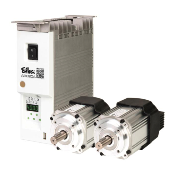
- AB620A5035 Scope of Supply Standard Scope of Supply Direct current motor DC1200 optional DC1250 Electronic control/Power supply unit AB620A5035N214 Set of accessories (standard) B156 Consisting of: Plastic bag for B156 + documentation Set of accessories Consisting of: 37-contact SubminD plug,... -
Page 8: Adapter Cords For Special Machines
Mounting kit for DC1230 on YAMATO VC, VE, VF, VG 1114102 2.1.1 Adapter Cords for Special Machines For interconnection diagrams of the adapter cords, please refer to our web site at www.efka.net/downloads. Machine / Type / Model Material No. AISIN high-speed seamer AD3XX, AD158, 3310 and overlock machine EK1... -
Page 9: Setting And Putting Into Service With The Aid Of The Fast Installation Routine (Sir)
- AB620A5035 Before putting the control into service, the following must be ensured, checked and/or adjusted: Selection of motor type using parameter 467 The correct installation of the drive, position transmitter and accompanying devices, if necessary The correct selection of the trimming operation using parameter 290 ... - Page 10 - AB620A5035 Input of the code number for the fitting level. Parameter 500 is displayed. Parameter 290 for functional sequence of the cutting procedures. Parameter 467 for selection of motor. Parameter 111 for the maximum speed.
- Page 11 - AB620A5035 Setting on the operating part of the controls (onboard) or on V810: 1 Input code number 3112! 2 Press the E key Parameter 5.0.0. displayed 3 Press the E key The V810 displays Sir displayed. the symbol [o].
- Page 12 - AB620A5035 Setting on the V820 control panel: 1 Input code number 3112! 2 Press the E key Parameter 500 displayed. 3 Press the E key Sir [o] displayed. (Functional cycle cutting 4 Press the >> key Parameter 290 FAm 05 appears.
-
Page 13: Quick Access
- AB620A5035 Quick access These are button combinations that are linked in the direct access with settings & function of the control. Quick access can, however, can only be used with machines that are already set up. 5.1 Parameter back up When the machine has been completely set up, the settings should be backed up. -
Page 14: Save The Parameter Backup On A Usb Stick
- AB620A5035 5.1.3 Save the parameter backup on a USB stick (The parameters can be views with a text editor or Microsoft Word. The parameters in this file must not be changed!) Insert an empty USB Wait until "USB" shows on the ... -
Page 15: Restoring The Parameter Backup From The Usb Stick
- AB620A5035 5.1.4 Restoring the parameter backup from the USB stick This process does not change the actual parameter settings. To load the backup to the current parameter setting, execute Chapter 5.1.2 "Restoring parameters from backup". (After this process) Insert the USB stick with ... -
Page 16: Setting The Reference Position
- AB620A5035 5.2 Setting the reference position (For detailed instructions refer to Chapter 6.9.1 Setting the Reference Position (Parameter 170) Hold down the button and Press the E button "P0" and a rotating switch on the controls "u"... -
Page 17: Setting The Basic Functions
- AB620A5035 Setting the Basic Functions 6.1 Direction of motor rotation Function with or without control panel Parameters Direction of motor rotation (drE) 161 =0 Clockwise motor rotation (look at the motor shaft) 161 =1 Counterclockwise motor rotation TTENTION If the motor is mounted differently, e. g. at a different angle or with gear, make sure that the value set using parameter 161 corresponds to the direction of rotation. -
Page 18: Transmission Ratio
- AB620A5035 6.3 Transmission Ratio The transmission ratio must always be input if no transmission ratio of 1:1 exists, because only motors with integrated incremental transmitters will be used. The transmission ratio should be determined and set as precisely as possible! The transmission ratio between motor shaft and shaft of the sewing machine head must be input, so that the set speeds of parameters 110...117 correspond to the sewing speeds. -
Page 19: Maximum Speed Compatible With The Sewing Machine
Transmission ratio between motor shaft and machine shaft (trr) A sensor can be used as a position sensor, e.g. Efka Hall sensor module (HSM1) or pulse generator (IPG) with either NC or NO functionality. It is connected to socket B18/7. -
Page 20: Setting The Reference Position (Parameter 170)
- AB620A5035 6.9.1 Setting the reference position (Parameter 170) The angular positions necessary on the machine e.g. “needle down position“ or “thread lever up position“ are stored in the control. A reference position is needed in order to establish a relationship between position transmitter information and actual mechanical position. -
Page 21: Setting The Positions
- AB620A5035 6.9.2 Setting the Positions This is an explanation of terms for the following descriptions: Position 1 means "Needle lower position" Position 2 means "Thread lever up" or "Needle rod TDC" Each position has a starting angle (start) and ending angle (end). The needle stop position always refers to the starting angle. -
Page 22: Positioning Shift
- AB620A5035 Control display (control panel not connected) Segment is turned on corresponds to position 1 On Segment is turned off corresponds to position 1 Off Segment is turned on corresponds to position 2 On ... -
Page 23: Starting Characteristics
- AB620A5035 6.14 Starting Characteristics Function with or without control panel Parameters Starting edge (ALF) The drive acceleration dynamics can be adapted to the sewing machine characteristic (light/heavy). High setting value = high acceleration With a high starting edge setting and, in addition, possibly high braking parameter values on a light machine, the characteristic may appear coarse. - Page 24 - AB620A5035 2. Service Hours Monitoring: 217 =>0 Operational mode: Number of operating hours before the next service. Input of operating hours before the next service. This value is compared to the operating hours counter. The input of hours is done in steps of 10. i. e. the lowest display of 001 corresponds to 10 hours (e.
-
Page 25: Set And Reset Operating Hours Counter
- AB620A5035 6.16.1 Set and Reset Operating Hours Counter The number of hours has been reached (service necessary): Press the >> key once The operating hours counter is set to "0" and restarted. The number of hours has not yet been reached: ... -
Page 26: Softstart Stitches
- AB620A5035 7.2.2 Softstart stitches Function with or without control panel Parameters Number of softstart stitches (SSc) 7.3 Sewing foot lifting Function without control panel Control Key – (S4) Automatic in the seam Segment 7 on Automatic after thread trimming... -
Page 27: Start Backtack/Start Stitch Condensing
- AB620A5035 TTENTION If the holding power is set too high, the solenoid and the control may be permanently damaged. Please observe the permissible duty ratio (ED) of the solenoid and set the appropriate value according to the table below. -
Page 28: Stitch Counting For Start Backtack/Start Stitch Condensing
- AB620A5035 7.4.2 Stitch Counting for Start Backtack/Start Stitch Condensing Function with or without control panel Parameters Number of stitches forward or without stitch regulator (c2) Number of stitches backward or with stitch regulator (c1) Double start backtack repetition (war) -
Page 29: Speed N4 At The Seam End
- AB620A5035 The end backtack/end stitch condensing in a seam with stitch counting starts by heelback at the end of counting, or, from the light barrier seam at the end of the light barrier compensating stitches. The stitch regulator is immediately enabled from machine standstill. -
Page 30: Single End Backtack / End Stitch Condensing
- AB620A5035 7.5.5 Single End Backtack / End Stitch Condensing The stitch regulator signal will be issued and the backward section and/or end stitch condensing will be executed for a number of stitches that can be set. During the last stitch the speed is reduced to positioning speed. -
Page 31: Intermediate Backtack
- AB620A5035 Function with control panel V810 V820 Function "ornamental backtack" On/Off (SrS) Ornamental backtack stop time (tSr) Single end backtack Left-hand arrow above Key 2 Key 4 Double end backtack key On, right-hand arrow End backtack Off above key On... -
Page 32: Stitch Regulator Suppression/Recall
- AB620A5035 7.9 Stitch Regulator Suppression/Recall Effective in standard and ornamental backtack The next backtack and/or stitch condensing operation can be suppressed or recalled once by pressing an external key according to the pre-selection of parameters 240...246. Upon pressing the... -
Page 33: Unlocking The Chain (Mode 5/6/7)
- AB620A5035 7.12 Unlocking the Chain (Mode 5/6/7) Function with or without control panel Parameters Number of run-out stitches when unlocking the chain (c6) Function “unlock the chain” in modes 5, 6 and 7 (mEk) Upon unlocking the chain at the seam end, the functions thread trimming and tape cutter/fast scissors are automatically suppressed. -
Page 34: Machine Run Blockage
- AB620A5035 7.13 Machine run blockage TTENTION This is not a safety function. The line voltage must still be switched off during maintenance and repair work. The function “machine run blockage” is enabled by connecting a switch to socket ST2, depending on the pre- selection of parameters 240...246. -
Page 35: High Lift Walking Speed Run-Out Time
- AB620A5035 7.14.2 High Lift Walking Speed Run-Out Time Function with or without control panel Parameters High Lift Walking Speed Run-Out Time (thP) 7.14.3 High Lift Walking Stitches Function with or without control panel Parameters Number of high lift walking stitches (chP) Upon pressing the external key “high lift for walking foot”... -
Page 36: Programming The Measurement Value Of The Poti
- AB620A5035 126 =7 Activated. The speed is limited to a value that depends on the lift level configured. The speed is limited in the range between the maximum speed (n2, parameter 111) for the minimum height, and a high lift walking speed (n10, parameter 117) for the maximum lift. -
Page 37: Thread Trimmer/Thread Wiper (Lockstitch Modes)
- AB620A5035 7.17.1 Thread Trimmer/Thread Wiper (Lockstitch Modes) Function Parameters Thread wiper time (t6) Thread wiper switch-on delay (dFw) Holding power output M1 of the thread trimmer backward (t11) Thread trimmer activation angle (iFA) Switch-off delay of thread tension release... -
Page 38: Functions For Bag Sewing Machines
- AB620A5035 7.18 Functions for bag sewing machines Function with or without control panel Parameters Chainstitch machine functions e. g. bag sewing machine functions (Bag) There are various setting possibilities in mode 5 using parameter 198: 198 =0 Thread trimming or hot thread chain cutting and sewing foot lifting are enabled by means of the pedal. - Page 39 - AB620A5035 Function with or without control panel Parameters Stop for tape cutting at the seam end On/Off (SAb) Sequence of the overlock mode (mode 7) with or without stop (UoS) Signal chain suction on seam end up to counted c2 or to pedal 0...
-
Page 40: Start And End Counts
- AB620A5035 7.19.2 Start and End Counts Function with or without control panel Parameters End count (c2) at limited speed n4 until stop (c2) Start count (c1) at limited speed n3 for chain suction (c1) Count (c3) tape cutter at the start of the seam... -
Page 41: Manual Tape Cutter/Fast Scissors
- AB620A5035 Tape cutter/Fast scissors at the start of the seam On left-hand arrow above Key 2 Key 4 Tape cutter/Fast scissors at the end of the seam On key On Tape cutter/Fast scissors at the start and end of the seam On... -
Page 42: Flipflop Functions (Aff)
- AB620A5035 7.22 FlipFlop functions (AFF) Function Parameters FlipFlop 1 (AFF1) Output assignment Linking F-830 =0 AFF1 =Off (preset) F-038 =0 Linking off (preset) F-830 =1 AFF1 =M1 F-038 =1 Linking with FSPL F-830 =2 AFF1 =M2 Linking with “high lift for walking foot”... -
Page 43: Seam With Stitch Counting
- AB620A5035 7.23 Seam with Stitch Counting Function without control panel Parameters Stitch counting On/Off (n7) Function with control panel V820 Stitch counting On/Off Key 2 7.23.1 Number of Stitches for a Seam with Stitch Counting Function with or without control panel... -
Page 44: Free Seam And Seam With Light Barrier
- AB620A5035 7.24 Free Seam and Seam with Light Barrier Function Parameters Positioning speed (n1) Upper limit of maximum speed (n2) Limited speed according to setting of parameter 142 (n12) Lower limit of maximum speed (n2_) Speed mode free seam (SFn) Speed control for the free seam and the seam with stitch counting can be selected using the speed mode. -
Page 45: Reflection Light Barrier Lsm002
- AB620A5035 Speed selection pedal controlled / n5 during the light barrier compensating stitches using parameter 192. The light barrier compensating stitches can be programmed and varied using the above parameters directly on the control or on a connected V810/V820 control panel. -
Page 46: Functional Variations Of The Light Barrier Input
- AB620A5035 7.25.6 Functional Variations of the Light Barrier Input Function Parameters Selection of the input function on socket B18/8 If the light barrier function is not used, a switching function can be assigned to the input on socket B18/8 as well as to inputs in1...i7. -
Page 47: Switching Functions Of Inputs In1
- AB620A5035 7.26 Switching Functions of Inputs in1...i13 Function Parameters 240...246 Selection of the input function (in1...in7) (in11-LSM) (in12...in13) 550...551 The functions of the keys/switches connected to socket connectors ST2, B18 and B22 can be selected for inputs in1...in13 using parameters 240...246, 239 (LSM), 550, 551. -
Page 48: Software Debouncing Of All Inputs
- AB620A5035 103 Signal AFF3 switchable as flip-flop: Upon pressing the key, signal AFF3 is activated and deactivated when pressing the key again, manual lock automatic 104 Manual lock automatic 105 -109 No function 109 Part lift mode 66 110 No function 111 Machine run blockage effective in Pos. -
Page 49: Special Pedal Function Single Stitch / Full Stitch
- AB620A5035 7.29 Special pedal function Single stitch / Full stitch Function Parameters Special pedal function Single stitch / Full stitch (EZP) Pedal travel forwards for detection of the special pedal function (GrP) Time for detection of the special pedal function... -
Page 50: Actuator
- AB620A5035 Independent of sewing, thus also when turning the handwheel manually Suitable e. g. for the connection of a counter A signal is issued at socket B18/1+6 7.34 Actuator 7.34.1 Analog actuator Function with or without control panel... -
Page 51: Signal Test Using The Incorporated Control Panel Or The
- AB620A5035 8.1 Signal Test Using the Incorporated Control Panel or the V810/V820 8.1.1 Inputs to the control Select parameter 173 (OFF is displayed). Control pad on controller: By actuating the keys or switches connected to inputs in1 to in7, the number of the input actuated appears on the display, e.g. -
Page 52: Table Of Machine Functions And Adapter Cords
- AB620A5035 Instruction Manual Table of Machine Functions and Adapter Cords TTENTION Before switching functional sequences, detach cables from the inputs and outputs! It must be absolutely certain that for the functional sequence to be changed the machine provided has... - Page 53 - AB620A5035 Instruction Manual Explanation of letter symbols of the above table and chapter ”Timing Diagrams“ Outputs Outputs Tape cutter Sewing foot lifting without pulsing AH1/AH2 Fast scissors FSPL Thread tension release Thread trimmer Thread wiper Thread trimmer pos. 1...1A...
-
Page 54: Operating Elements And Socket Connectors
- AB620A5035 Instruction Manual 10 Operating Elements and Socket Connectors 10.1 Positions of the Front Side Power switch Network control lights Control panel (onboard module) + Display (4-digit 7-segment display) Call or exit programming mode Start backtack single / double / off... -
Page 55: Connection Diagrams
- AB620A5035 Instruction Manual 10.3 Connection Diagrams Inputs switched to 0V TTENTION When connecting the outputs, ensure that a total power of 96VA constant load will not be exceeded! Input 1 R-N-EXT External potentiometer for speed limitatiom Output 4 Input 2... - Page 56 - AB620A5035 Instruction Manual Inputs switched to +24 V TTENTION When connecting the outputs, ensure that a total power of 96VA constant load will not be exceeded! 1) Nominal voltage +24 V, no-load voltage max. +30 V momentarily after power on 2) Transistor output with open collector max.
- Page 57 - AB620A5035 Instruction Manual Connection of a HSM001 Hall sensor module or Connection of a light barrier module an IPG001 pulse encoder LSM002 POS2 POS2 +5V (2) +5V (2) OUT (4) OUT (4) OUT (4) OUT (4) OUT (4) OUT (4) SUB-D-9 (*) HSM.../IPG...
- Page 58 - AB620A5035 Instruction Manual (F-550) (F-551) N.C. IN12 IN13 +24V (1) N.C. RJ11(6P4C)*) BI1179 IN12 Input 12, function programmable using IN13 Input 13, function programmable using parameter 550 parameter 551 Connecting the analogous actuator EB401 EB.. = Actuator Code table for digital target value preset (grey code) Pedal step ...
- Page 59 - AB620A5035 Instruction Manual Connection for frequency run Connections: 0 V on Pin 1 Frequency output on Pin 4 Frequency controller output on Pin 7 In order to introduce motor running 0V must be applied to pin 7 Frequency rates: 0-5 V / 200-10000 Hz −1...
-
Page 60: Timing Diagrams
- AB620A5035 Instruction Manual 11 Timing Diagrams Mode 0 (lockstitch) Mark Function Parameters Control V810 V820 Mode 0 290 =0/27 Double start backtack with stitch correction Key E Key 1 Key 1 Double end backtack with stitch correction Key +... - Page 61 - AB620A5035 Instruction Manual Mode 2 (lockstitch) Mark Function Parameters Control V810 V820 Mode 2 290 =2 Softstart 134 =1 Key E Single start backtack Key 1 Key 1 Single end backtack Key + Key 2 Key 4 Positioning speed...
- Page 62 - AB620A5035 Instruction Manual Mode 3 (lockstitch) Mark Function Parameters Control V810 V820 Mode 3 290 =3 Key E Double start backtack Key 1 Key 1 Key + Double end backtack Key 2 Key 4 High lift for walking foot...
- Page 63 - AB620A5035 Instruction Manual Mode 5 (chainstitch) Mark Function Parameters Control V810 V820 Mode 5 290 =5 Softstart 134 =1 Start stitch condensing Key E Key 1 Key 1 Key + End stitch condensing Key 2 Key 4 Positioning speed...
- Page 64 - AB620A5035 Instruction Manual Mode 5, 6 or 7 (function “unlocking the chain” with light barrier) Mark Function Parameters Control V810 V820 Mode 5 290 =5 Direction of motor rotation Right 161 =0 Reverse motor rotation 182 =1 Key >>...
- Page 65 - AB620A5035 Instruction Manual Mode 5, 6 or 7 (function “unlocking the chain”) Mark Function Parameters Control V810 V820 Mode 5 290 =5 Direction of motor rotation Right 161 =0 Reverse motor rotation 182 =1 Basic position 2 Key >>...
- Page 66 - AB620A5035 Instruction Manual Mode 6 (chainstitch with fast scissors) parameter 232 = 1 Mark Function Parameters Control V810 V820 Mode 6 290 =6 Softstart 134 =1 Start stitch condensing Key E Key 1 Key 1 Chainstitch with fast scissors M3/M4...
- Page 67 - AB620A5035 Instruction Manual Mode 7 (overlock) parameter 232 = 0 (tape cutter) / parameter 018 = 0 (seam end with stop) Mark Function Parameters Control V810 V820 Mode 7 290 = 7 Counts c1, c2, c3 and c4 Key 1/4...
- Page 68 - AB620A5035 Instruction Manual Mode 7 (overlock) parameter 232 = 1 (fast scissors) / parameter 018 = 0 (seam end with stop) Mark Function Parameters Control V810 V820 Mode 7 290 = 7 Counts c1, c2, c3 and c4 Key 1/4...
- Page 69 - AB620A5035 Instruction Manual Mode 7 (overlock) parameter 232 = 0 (tape cutter) / parameter 018 = 1 (seam end without stop) Mark Function Parameters Control V810 V820 Mode 7 290 = 7 Counts c1, c2, c3 and c4 Key 1/4...
- Page 70 - AB620A5035 Instruction Manual Mode 7 (overlock) chain suction permanent signal Mark Function Parameters Chain suction 155 = 1 Speed F-156 Switch-off delay for M2 156 = 200ms - 70 -...
- Page 71 - AB620A5035 Instruction Manual Mode 7 (overlock) chain suction via stitch count (Ecco) Mark Function Parameters Chain suction 155 = 5 Speed Stitches for motor run Ecco On 084 = 5 Stitches for motor run Ecco Off 085 = 4...
- Page 72 - AB620A5035 Instruction Manual Mode 7 (overlock) Chain suction controlled via light barrier Mark Function Parameters Control Sewing foot lifting at the seam end Light barrier Key - 009 =1 Sequence “overlock mode with stop” 018 =0 Function “pedal in pos. –2” blocked...
- Page 73 - AB620A5035 Instruction Manual Mode 7 (overlock) chain suction controlled via light barrier and chain suction signal interrupted during stop Mark Function Parameters Control Sewing foot lifting at the seam end Light barrier Key - 009 =1 Sequence “overlock mode with stop”...
- Page 74 - AB620A5035 Instruction Manual Mode 8 (backlatch Pegasus) Mark Function Parameters Control V810 V820 Mode 8 290 =8 Basic position 2 Key 4 Key 7 Key >> Softstart 134 =1 Machine run blockage activated with open switch 240 =6 n-Auto with closed switch...
- Page 75 - AB620A5035 Instruction Manual Mode 9 (backlatch Yamato) Mark Function Parameters Control V810 V820 Mode 9 290 =9 Basic position 2 Key 4 Key 7 Key >> Softstart 134 =1 Machine run blockage activated with open switch 240 =6 Automatic speed on an open switch...
- Page 76 - AB620A5035 Instruction Manual Mode 14 (lockstitch) Mark Function Parameters Control V810 V820 Mode 14 290=14 Double start backtack with stitch correction Key E Key 1 Key 1 Key + Double end backtack with stitch correction Key 2 Key 4 Setting an external sensor to position 1.
- Page 77 - AB620A5035 Instruction Manual Mode 17 (Stitchlock Pegasus) Mark Function Parameter Control V810 V820/V850 Mode 17 290=17 Positon 2 Button S5 Button 4 Button 7 Trimmer and Thread wiper Button S2 Button 5 Positioning speed Maximum speed Trimming speed dr°...
- Page 78 - AB620A5035 Instruction Manual Mode 21 (Stitchlock Yamato) Mark Function Parameter Control V810 V820/V850 Mode 21 290 = 21 Stitchlock-Function 196 = 1 Button S2 Button Button 1 Start backtack Button S3 Button 4 End backtack Button Setting an external sensor to position 2.
- Page 79 - AB620A5035 Instruction Manual Mode 25 (lockstitch Juki LU2210 / LU2260) Mark Function Parameters Control V810 V820 Mode 25 290 =25 Double start backtack Key E Key 1 Key 1 Key + Double end backtack Key 2 Key 4 External potentiometer is active...
-
Page 80: Operator Level
- AB620A5035 Instruction Manual 11.1 Operator Level Note The preset values indicated apply to mode 0 (Parameter 290 = 0). For preset values applicable to other modes see table in chapter 11.1 »Preset Values Depending on Mode«. Parameters Designation Unit Preset Ind. - Page 81 - AB620A5035 Instruction Manual Parameters Designation Unit Preset Ind. -Pd 0 = Pedal in pos. -1 blocked in the seam. But with pedal in pos. -2 sewing foot lifting is possible in the seam (function active whenever the light barrier is On) 1 = With pedal in pos.
- Page 82 - AB620A5035 Instruction Manual 3 = Switched off when the foot is lifted or locked. Parameters Designation Unit Preset Ind. EZP Special pedal function Single stitch / Full stitch 0 = Function Off 1 = Single stitch (assuming needle up to needle down). Afterwards...
-
Page 83: Technical Level (Code No. 1907)
- AB620A5035 Instruction Manual 11.2 Technical level (Code no. 1907) Parameters Designation Unit Preset Ind. Number of softstart stitches Stitches EvA Switch-on start backtack for the backtacking solenoid in the initial backtack AvA Power-off start backtack for the backtacking solenoid in... - Page 84 - AB620A5035 Instruction Manual Parameters Designation Unit Preset Ind. LSE Thread trimming operation, when completing the seam after light barrier sensing On/Off SSt Softstart On/Off SrS Ornamental backtack On/Off FAr 0 = Trimming stitch backward Off 1 = Trimming stitch backward On with single end backtack...
- Page 85 - AB620A5035 Instruction Manual Parameters Designation Unit Preset Ind. Mode signal run 0 = Signal Off. 1 = Signal run On. 2 = Signal “run” enabled when the speed is >3000 RPM. 3 = Signal with pedal <> 0. 4 = Signal enabled only after motor synchronization (one rotation at positioning speed after power On).
- Page 86 - AB620A5035 Instruction Manual Press the E key Display Press the E key Display Press the E key Display MSEc Press the E key Display Press the P key twice Display e.g. Ab620A Display of control program number with index and more identification numbers.
- Page 87 - AB620A5035 Instruction Manual Enable chain suction signal and thread tension release 0 = Thread tension release and chain suction after the light barrier compensating stitches 1 = Chain suction from light barrier uncovered onwards and thread tension release after the light barrier compensating stitches Functions with chainstitch machines e.
-
Page 88: Supplier Level (Code No. 3112)
- AB620A5035 Instruction Manual 11.3 Supplier level (Code No. 3112) Parameters Designation Unit Preset Ind. Start backtack until speed release after start backtack Sewing foot switch-on start backtack after thread wiper 2550 with half heelback Start start backtack after disabling the sewing foot lifting... - Page 89 - AB620A5035 Instruction Manual Supplier level (Code No. 3112) Parameters Designation Unit Preset Ind. in1 Selection of the input functions on socket ST2/7 for input 1 0 = No function 1 = Needle up/down 2 = Needle up 3 = Single stitch (basting stitch)
- Page 90 - AB620A5035 Instruction Manual Parameters Designation Unit Preset Ind. in4 Selection of input function on socket ST2/8 for input 4 0 = No function All other functions of the keys as with parameter 240 in5 Selection of input function on socket ST2/5 for input 5...
- Page 91 - AB620A5035 Instruction Manual FAm Selection of machine specific mode 0 = Lockstitch: (FA1, FA2, FA3, FA1+FA2): e.g. BrotherDürkopp Adler, Mitsubishi, Pfaff, Toyota »Slide-in strips for V810/V820 =1/1« 1 = No Function 2 = Lockstitch: e.g. Singer (212 UTT) »Slide-in strips for V810/V820 =1/1«...
- Page 92 - AB620A5035 Instruction Manual 63 = Lockstitch: Juki DNU 1541-7 »Slide-in strips for V810/V820 =5/2« 64 = No function 65 = Chainstitch: Sagitta »Slide-in strips for V810/V820 =5/2« 66 = Chainstitch: Strobel VTD 410EV »Slide-in strips for V810/V820 =5/2« 67 = Chainstitch: Hengtai MP500»Slide-in strips for V810/V820...
- Page 93 - AB620A5035 Instruction Manual Parameters Designation Unit Preset Ind. tF2 Selection of the input function using key (B) “F2” on the V810/V820 control panel Functions of the key as with parameter 293, but at setting 0 key F2 is disabled.
- Page 94 See Section Fehler! Verweisquelle konnte nicht gefunden werden. Setting the Positions (Parameter 270 = 0 or 6) MOT Selection of motor 1 = Efka DC1500 (512) 2 = Efka DC1550 (512) 3 = Efka DC1200 (512) 4 = Efka DC1250 (512)
- Page 95 - AB620A5035 Instruction Manual Parameters Designation Unit Preset Ind. in12 Selection of input function on socket B22/3 for input 12 0 = No function All other functions of the keys as with parameter 240 in13 Selection of input function on socket B22/4 for input 13...
-
Page 96: Error Displays
- AB620A5035 Instruction Manual APt Service routine to teach the analog pedal. Pedal forwards for standing operation User-defined functi on strips for V860 Off (selection of function strip using F-292) User-defined function strips 1 User-defined function strips 2 User-defined function strips 3 User-defined function strips 4 ... - Page 97 - AB620A5035 Instruction Manual Serious Condition The external pulse encoder e.g. IPG... is defective or not connected Line voltage too low, or time between power Off and power On too short Machine blocked or does not reach the desired speed...
- Page 99 Instruction Manual with parameter List AB620A5035 Distribution: --- For your notes:...
- Page 100 - AB620A5035 Parameter List For your notes: - 94 -...
- Page 101 - AB620A5035 Parameter List For your notes: - 95 -...
- Page 102 - AB620A5035 Parameter List For your notes: - 96 -...
- Page 103 - AB620A5035 Parameter List For your notes: - 97 -...
- Page 104 3715 NORTHCREST ROAD – SUITE 10 – ATLANTA – GEORGIA 30340 PHONE: +1-770-457 7006 – FAX: +1-770-458 3899 – email: efkaus@bellsouth.net EFKA SINGAPORE PTE. LTD. 67, AYER RAJAH CRESCENT 05-03 – SINGAPORE 139950 PHONE: +65-67772459 – FAX: +65-67771048 – email: efkaems@efka.net 2-140318-B (402446 EN) - 98 -...
Need help?
Do you have a question about the AB620A5035 and is the answer not in the manual?
Questions and answers