Table of Contents
Advertisement
Advertisement
Table of Contents

Related Manuals for Efka AB600A5010


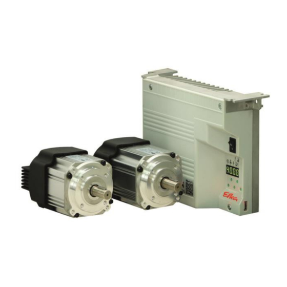
Summary of Contents for Efka AB600A5010
- Page 1 CONTROL AB600A5010 Operating manual With parameter list - Putting into Service - Settings - Functional Description - Connection Diagrams - Timing Diagrams No. 402447 English FRANKL & KIRCHNER EFKA OF AMERICA INC. EFKA SINGAPORE PTE. LTD GMBH & CO KG...
- Page 2 They may differ from those in your display. For current versions of the Instructions for Use and Lists of Parameters, necessary for operating EFKA drives in accordance with regulations, please refer to the EFKA web site www.efka.net, page “Downloads”.
-
Page 3: Table Of Contents
- AB AB600A5010 Instruction Manual CONTENTS Page 1 Range of Applications Use in Accordance with Regulations 2 Scope of Supply Special Accessories 3 Putting into Service 4 Setting and Putting into Service with the Aid of the Fast Installation Routine (SIR) - Page 4 - AB600A5010 Instruction Manual 7.6.4 Chainstitch Machine Trimming Signal Times Overlock Machine Functions (Mode 7) 7.7.1 Start and End Counts Tape Cutter/Fast Scissors (Modes 6/7) 7.8.1 Tape Cutter/Fast Scissors in Mode 7 Manual Tape Cutter/Fast Scissors 7.10 Seam with Stitch Counting 7.10.1...
- Page 5 - AB AB600A5010 Instruction Manual - 5 -...
-
Page 6: Range Of Applications
- AB600A5010 Instruction Manual Range of Applications The drive is suitable for lockstitch, chainstitch and overlock machines of various manufacturers. The functions backtacking and stitch compression, are unsupported. 1.1 Use in Accordance with Regulations The drive is not an independent functional machine. It has been designed for integration into other machines by trained specialists. -
Page 7: Special Accessories
- AB AB600A5010 Instruction Manual 2.1 Special Accessories The special accessories available ex works allow the augmentation and enhancement of functions, operating, connecting, and mounting options.Since the range of available components is continually expanded, we kindly ask you to contact us in case of need. - Page 8 - AB600A5010 Instruction Manual With SIR you can do the most important settings for initial operation with menu prompting. For safety reasons, the menu must be executed point by point. This ensures correct setting of all important parameters. Input of the code number for the fitting level.
- Page 9 - AB AB600A5010 Instruction Manual Setting on the operating part of the controls (onboard) 1 Input code number 3112! 2 Press the E key Parameter 5.0.0. displayed 3 Press the E key Sir displayed. The 2 lower segments of the right 7 segment display flash.
-
Page 10: Quick Access
- AB600A5010 Instruction Manual Quick access These are button combinations that are linked in the direct access with settings & function of the control. Quick access can, however, can only be used with machines that are already set up. 5.1 Parameter back up When the machine has been completely set up, the settings should be backed up. -
Page 11: Save The Parameter Backup On A Usb Stick
- AB AB600A5010 Instruction Manual 5.1.3 Save the parameter backup on a USB stick (The parameters can be views with a text editor or Microsoft Word. The parameters in this file must not be changed!) Insert an empty USB ... -
Page 12: Restoring The Parameter Backup From The Usb Stick
- AB600A5010 Instruction Manual 5.1.4 Restoring the parameter backup from the USB stick This process does not change the actual parameter settings. To load the backup to the current parameter setting, execute Chapter 5.1.2 "Restoring parameters from backup". (After this process) ... -
Page 13: Setting The Reference Position
- AB AB600A5010 Instruction Manual 5.2 Setting the reference position (For detailed instructions refer to Chapter 6.9.1 Setting the Reference Position (Parameter 170) Hold down the button and Press the E button "P0" and a rotating switch on the controls "u"... -
Page 14: Setting The Basic Functions
- AB600A5010 Instruction Manual Setting the Basic Functions 6.1 Direction of motor rotation Function Parameters Direction of motor rotation (drE) 161 =0 Clockwise motor rotation (look at the motor shaft) 161 =1 Counterclockwise motor rotation TTENTION If the motor is mounted differently, e. g. at a different angle or with gear, make sure that the value set using parameter 161 corresponds to the direction of rotation. -
Page 15: Transmission Ratio
- AB AB600A5010 Instruction Manual 6.3 Transmission Ratio The transmission ratio must always be input if no transmission ratio of 1:1 exists, because only motors with integrated incremental transmitters will be used. The transmission ratio should be determined and set as... -
Page 16: Maximum Speed Compatible With The Sewing Machine
Transmission ratio between motor shaft and machine shaft (trr) A sensor can be used as a position sensor, e.g. Efka Hall sensor module (HSM1) or pulse generator (IPG) with either NC or NO functionality. It is connected to socket B18/7. -
Page 17: Setting The Reference Position (Parameter 170)
- AB AB600A5010 Instruction Manual 6.9.1 Setting the reference position (Parameter 170) The angular positions necessary on the machine e.g. “needle down position“ or “thread lever up position“ are stored in the control. A reference position is needed in order to establish a relationship between position transmitter information and actual mechanical position. -
Page 18: Control Display Of Signal Position And Stop Position
- AB600A5010 Instruction Manual 6.10 Control display of signal position and stop position Function Parameter Display of position 1 and 2 (Sr3) Control display Segment is turned on corresponds to position 1 On Segment is turned off corresponds to position 1 Off ... -
Page 19: Starting Characteristics
- AB AB600A5010 Instruction Manual 6.14 Starting Characteristics Function Parameters Starting edge (ALF) The drive acceleration dynamics can be adapted to the sewing machine characteristic (light/heavy). High setting value = high acceleration With a high starting edge setting and, in addition, possibly high braking parameter values on a light machine, the characteristic may appear coarse. -
Page 20: Set And Reset Operating Hours Counter
- AB600A5010 Instruction Manual 6.15.1 Set and Reset Operating Hours Counter The number of hours has been reached (service necessary): Press the >> key once The operating hours counter is set to "0" and restarted. The number of hours has not yet been reached: ... -
Page 21: Sewing Foot Lifting
- AB AB600A5010 Instruction Manual Sewing foot lifting Function Control Key – (S4) Automatic in the seam Segment 7 on Automatic after thread trimming Segment 8 on Function Parameters Automatic sewing foot with pedal forward at the seam end if light barrier or stitch... -
Page 22: Unlocking The Chain (Mode 5/6/7)
- AB600A5010 Instruction Manual 7.4 Unlocking the Chain (Mode 5/6/7) Function Parameters Number of run-out stitches when unlocking the chain (c6) Function “unlock the chain” in modes 5, 6 and 7 (mEk) Upon unlocking the chain at the seam end, the functions thread trimming and tape cutter/fast scissors are automatically suppressed. -
Page 23: Machine Run Blockage
- AB AB600A5010 Instruction Manual 7.5 Machine run blockage TTENTION This is not a safety function. The line voltage must still be switched off during maintenance and repair work. The function “machine run blockage” is enabled by connecting a switch to socket B3, depending on the pre -... -
Page 24: Chainstitch Thread Cutter (Var. Modes)
- AB600A5010 Instruction Manual 7.6.3 Chainstitch thread cutter (var. modes) Thread trimming in the chainstitch modes is performed at machine standstill in position 2. The signal sequence of M1...M4 and sewing foot lifting at the seam end can be set as desired using parameters 280...288 (Parallel or sequential). -
Page 25: Tape Cutter/Fast Scissors (Modes 6/7)
- AB AB600A5010 Instruction Manual 7.8 Tape Cutter/Fast Scissors (Modes 6/7) The signal tape cutter/fast scissors is issued only at the seam end. Furthermore, the manual tape cutter/fast scissors function can be set. See also chapter "Manual Tape Cutter/Fast Scissors". -
Page 26: Stitch Counting Speed
- AB600A5010 Instruction Manual 7.10.2 Stitch Counting Speed Function Parameters (n1) Positioning speed (n12) Stitch Counting Speed (SGn) Speed mode for a seam with stitch counting A certain speed behavior for the stitch counting can be selected using parameter141. 141 =0... -
Page 27: Light Barrier
- AB AB600A5010 Instruction Manual 7.12 Light barrier Function Parameters Light barrier On/Off The light barrier function at the input of socket B18/8 is active only if parameter value 239 = 0. 7.12.1 Speed after Light Barrier Sensing Function Parameters... -
Page 28: Automatic Start Controlled By Light Barrier
- AB600A5010 Instruction Manual 7.12.4 Automatic Start Controlled by Light Barrier This function is not possible when parameter F-290 =8 or 9 (modes 8 and 9)! Function Parameters (ASd) Delay of automatic start (ALS) Automatic start On/Off (LSd) Light barrier sensing uncovered... -
Page 29: Switching Functions Of Inputs In1
- AB AB600A5010 Instruction Manual 7.13 Switching Functions of Inputs in1...i13 Function Parameters (in1...in7) Selection of the input function (in11-LSM) The functions of the keys/switches connected to socket connectors ST2, B18 and B22 can be select ed for inputs in1...in13 using parameters 240 and 239 (LSM),... -
Page 30: Special Pedal Function Single Stitch / Full Stitch
- AB600A5010 Instruction Manual 7.15 Special pedal function Single stitch / Full stitch Function Parameters (EZP) Special pedal function Single stitch / Full stitch (GrP) Pedal travel forwards for detection of the special pedal function (dPd) Time for detection of the special pedal function... -
Page 31: Actuator
- AB AB600A5010 Instruction Manual 7.19 Actuator 7.19.1 Analog actuator Function Parameter (-Pd) Selectable pedal functions (APd) Characteristic of the "analog pedal" EB401 (plu) Area for position +1/2 of “analog pedal” in percent (nSt) Speed- step distrinution The effect of pedal actuation on the drive functions can be set using parameter 019: 019 = 0 Pedal in pos. -
Page 32: Outputs Of Control
- AB600A5010 Instruction Manual 8.1.1 Outputs of control Select parameter 173 (OFF is displayed). Select the desired output using the +/- keys. On the built-in keypad in the control, the >> key is used to turn on the associated output, if it is connected and working. -
Page 33: Table Of Machine Functions And Adapter Cords
- AB600A5010 Parameter List Table of Machine Functions and Adapter Cords TTENTION Before switching functional sequences, detach cables from the inputs and outputs! It must be absolutely certain that for the functional sequence to be changed the machine provided has... -
Page 34: Operating Elements And Socket Connectors
- AB600A5010 Parameter List 10 Operating Elements and Socket Connectors 10.1 Positions of the Front Side Power switch Network control lights Control panel (onboard module) + Display (4-digit 7-segment display) Call or exit programming mode Start backtack single / double / off... -
Page 35: Connection Diagrams
- AB600A5010 Parameter List 10.3 Connection Diagrams Inputs switched to 0V TTENTION When connecting the outputs, ensure that a total power of 96VA constant load will not be exceeded! Input 1 Output 2 Output 1 Output 3 1) Nominal voltage +24V, no-load voltage max. +30V momentarily after power on... - Page 36 - AB600A5010 Parameter List Connection of a HSM001 Hall sensor module or Connection of a light barrier module an IPG001 pulse encoder LSM002 Adapter cord 1113229 in case of multiple assignment of socket B18! POS2 OUT Output for position 2...
- Page 37 - AB600A5010 Parameter List Connecting the analogous actuator EB401 EB.. = Actuator Connection for frequency run Connections: 0 V on Pin 1 Frequency output on Pin 4 Frequency controller output on Pin 7 In order to introduce motor running 0V must be applied to pin 7 Frequency rates: 0-5 V / 200-10000 Hz −1...
-
Page 38: Timing Diagrams
- AB600A5010 Parameter List 11 Timing Diagrams Mode 0 (lockstitch) Mark Function Parameter Control Mode 0 290 = 0 speed Positioning Maximum speed Trimming speed Start delay from lifted sewing foot Sewing foot lifting switch-on delay after thread wiper - 38 -... - Page 39 - AB600A5010 Parameter List Mode 5 (chainstitch) Mark Function Parameter Control Mode 5 290 = 5 134 = 1 Softstart speed Positioning Maximum speed Softstart speed Trimming speed Softstart stitches Start delay from lifted sewing foot Switch-on delay of sewing foot lifting...
- Page 40 - AB600A5010 Parameter List Mode 5, 6 or 7 (function “unlocking the chain” with light barrier) Mark Function Parameter Control 290 = 5 Mode Clockwise 161 = 0 Direction of motor rotation 182 = 1 Reverse motor rotation Key >>...
- Page 41 - AB600A5010 Parameter List Mode 5, 6 or 7 (function “unlocking the chain”) Mark Function Parameter Control 290 = 5 Mode Clockwi 161 = 0 Direction of motor rotation 182 = 1 Reverse motor rotation Key >> Basic position 2 Thread trimmer *) Assign the function “unlocking the chain”...
- Page 42 - AB600A5010 Parameter List Mode 6 (chainstitch with fast scissors) parameter 232 = 1 Mark Function Parameter Control Mode 6 290 = 6 134 = 1 Softstart 232 = 1 Chainstitch with fast scissors M1/M2 Maximum speed Softstart speed Trimming speed...
- Page 43 - AB600A5010 Parameter List Mode 7 (overlock) parameter 232 = 0 (tape cutter) / parameter 018 = 0 (seam end with stop) Mark Function Parameter Control 290 = 7 Mode Key - Sewing foot lifting at the seam end 009 = 1 Light barrier Sequence “overlock mode with stop”...
- Page 44 - AB600A5010 Parameter List Mode 7 (overlock) parameter 232 = 1 (fast scissors) / parameter 018 = 0 (seam end with stop) Mark Function Parameter Control Mode 7 290 = 7 Key - Sewing foot lifting at the seam end...
- Page 45 - AB600A5010 Parameter List Mode 7 (overlock) parameter 232 = 0 (tape cutter) / parameter 018 = 1 (seam end without stop) Mark Function Parameter Control 290 = 7 Mode 004 = 0 Light barrier compensating stitches 009 = 1 Light barrier Sequence “overlock mode at the seam end without...
- Page 46 - AB600A5010 Parameter List Mode 7 (overlock) chain suction permanent signal Mark Function Parameters Chain suction 155 = 1 Speed 156 = 200ms F-156 Switch-off delay for M2 - 46 -...
- Page 47 - AB600A5010 Parameter List Mode 7 (overlock) chain suction via stitch count (Ecco) Mark Function Parameters Chain suction 155 = 5 Speed 084 = 5 Stitches for motor run Ecco On 085 = 4 Stitches for motor run Ecco Off...
- Page 48 - AB600A5010 Parameter List Mode 7 (overlock) Chain suction controlled via light barrier Mark Function Parameters Control Sewing lifting at the seam end foot Light barrier 009 =1 Key - Sequence “overlock mode with stop” 018 =0 Function “pedal in pos. –2” blocked...
- Page 49 - AB600A5010 Parameter List Mode 7 (overlock) chain suction controlled via light barrier and chain suction signal interrupted during stop Mark Function Parameters Control Sewing foot lifting at the seam end Light barrier 009 =1 Key - Sequence “overlock mode with stop”...
-
Page 50: Parameterlist
- AB600A5010 Parameter List 12 Parameterlist 12.1 Operator Level The preset values indicated apply to mode 0 (Parameter 290 = 0). For preset values applicable to other modes see table in chapter 11.1 »Preset Values Depending on Mode«. Parameters Designation... - Page 51 - AB600A5010 Parameter List Parameters Designation Unit Preset Ind. -Pd 0 = Pedal in pos. -1 blocked in the seam. But with pedal in pos. -2 sewing foot lifting is possible in the seam (function active whenever the light barrier is On) 1 = With pedal in pos.
-
Page 52: Technical Level (Code No. 1907)
- AB600A5010 Parameter List 12.2 Technical level (Code no. 1907) Parameters Designation Unit Preset Ind. SSc Number of softstart stitches Stitches n1 Positioning speed for threading (mode 66) n2 Upper limit setting range of the maximum speed 9900 5000 n5 Speed after light barrier sensing... - Page 53 - AB600A5010 Parameter List Parameters Designation Unit Preset Ind. LSG Mode signal run 0 = Signal Off. 1 = Signal run On. 2 = Signal “run” enabled when the speed is >3000 RPM. 3 = Signal with pedal <> 0.
- Page 54 - AB600A5010 Parameter List Parameters Designation Unit Preset Ind. Reversing angle Degrees 359 Switch-on delay of reverse motor rotation Reverse motor rotation On/Off Number of run-out stitches when unlocking the chain Stitches Function “unlock the chain” in m odes 5, 6 and 7 (Parameter 290) 0 = Unlocking off 1 = Unlocking the chain manually (with pedal in pos.
-
Page 55: Supplier Level (Code No. 3112)
- AB600A5010 Parameter List Supplier level 12.3 (Code No. 3112) Parameters Designation Unit Preset Ind. Sewing foot switch-on delay after thread wiper with half 2550 heelback Start delay after disabling the sewing foot lifting signal Time of full power of sewing foot lifting... - Page 56 - AB600A5010 Parameter List Supplier level (Code No. 3112) Parameters Designation Unit Preset Ind. in1 Selection of input function on socket ST2/7 for input 1 0 = No function 1 = Needle up/down 2 = Needle up 3 = Single stitch (basting stitch)
- Page 57 - AB600A5010 Parameter List Parameters Designation Unit Preset Ind. trr Transmission ratio between motor shaft and machine s haft 40000 1000 (calculation formula see instruction manual!) The transmission ratio should be determined and indicated as precisely as possible! kd1 Delay time output M1...
- Page 58 End position 2 thread lever up" / "Needle rod OT" See Section 6.9.2.Setting the Positions (Parameter 270 = 0 or 6) MOT Selection of motor 1 = Efka DC1500 (512) 2 = Efka DC1550 (512) 3 = Efka DC1200 (512)
-
Page 59: Error Displays
- AB600A5010 Parameter List 13 Error Displays On the control Signification General Information Pedal not in neutral position when turning the machine on Machine run blockage Reference position is not set No thread trimming mode available in parameter 290 High lift foot for walking - measurement of the potis not permitted A500 Max. - Page 61 Instruction Manual with parameter List Distribution: --- For your notes:...
- Page 62 Parameter list For your notes: - 94 -...
- Page 63 - AB620A5030 + 5032 Parameter list For your notes: - 95 -...
- Page 64 3715 NORTHCREST ROAD – SUITE 10 – ATLANTA – GEORGIA 30340 PHONE: +1-770-457 7006 – FAX: +1-770-458 3899 – email: efkaus@bellsouth.net EFKA SINGAPORE PTE. LTD. 67, AYER RAJAH CRESCENT 05-03 – SINGAPORE 139950 PHONE: +65-67772459 – FAX: +65-67771048 – email: efkaems@efka.net 1(2)-060618-B (402447 EN) - 96 -...
Need help?
Do you have a question about the AB600A5010 and is the answer not in the manual?
Questions and answers
How to fix problem error A2?