IDEAL Networks LanTEK IV User Manua
Hide thumbs
Also See for LanTEK IV:
- Quick reference manual (80 pages) ,
- Quick reference manual (15 pages) ,
- Manual (5 pages)

Related Manuals for IDEAL Networks LanTEK IV


Summary of Contents for IDEAL Networks LanTEK IV
- Page 1 LanTEK IV The Future of Cable Certification User Manual Proof of Performance Proof of Performance...
- Page 2 LanTEK IV User Manual © IDEAL INDUSTRIES Networks Ltd 2020 The information contained in this document is the property of IDEAL INDUSTRIES Networks Ltd. and is supplied without liability for errors and omissions. No part of this document may be reproduced or used except as authorized by contract or other written permission from IDEAL INDUSTRIES Networks Ltd.
-
Page 3: Table Of Contents
Content Safety Instructions Responsibilities Certification Link Models IDEAL AnyWARE Cloud LanTEK IV Configuration: Settings Menu Default Autotest Settings Wi-Fi Settings Importing/Exporting Jobs User Interface Operating Modes Standard User Interface Operation - explained Live Wiremap Creating Test Files Presentation of Tests... -
Page 4: Safety Instructions
Safety instructions Warnings for handling the rechargeable batteries of LanTEK IV. All Lithium-Ion (Li-Ion) batteries generate a significant flow of electric current, irrespective of the indicated state of charge, which can cause personal injury and / or property damage. Lithium ion (Li-Ion) batteries should not be burned or disposed of with normal waste. -
Page 5: Responsibilities
Responsibilities IDEAL INDUSTRIES NETWORKS LTD is not responsible for death, personal injury, device damage or property damage caused by improper use of rechargeable batteries. IDEAL INDUSTRIES NETWORKS LTD is not responsible for consequential damages caused by modifications of the rechargeable batteries or the charger and their subsequent use. -
Page 6: Certification Link Models
Certification Link Models MPTL (Modular Plug Terminated Link) configuration Included in the test: • Connection between the Permanent link adapter plug and the MPTL socket • Connection between MPTL plug and patch cord adapter Not included in the test: • Permanent link adapter cord Permanent Link configuration Included in the test:... - Page 7 Certification Link Models The typical method is the Permanent Link to certify the infrastructure fixed wiring consisting of two female RJ45 sockets at each end and an optional consolidation point connector near the work area. The Channel method has the advantage of also certifying the two patch cords connected to the permanent link thus measuring the entire channel from end- to end.
-
Page 8: Ideal Anyware Cloud
PC. Create an account at https://anyware.idealnetworks.net Please use: Google Chrome, Microsoft Edge, or Mozilla Firefox. IDEAL AnyWARE CLOUD allows management of projects using LanTEK IV certifiers. Who has the certifier Date of last software update... - Page 9 IDEAL AnyWARE Cloud Please register your LanTEK IV to receive updated information at: https://www.idealnetworks.net An account is required to download software and documentation. Link LanTEK IV to your AnyWARE account. Select the Navigation menu: Select "Device", add your LanTEK IV with on the menu at the top right.
- Page 10 IDEAL AnyWARE Cloud You will find the Device ID in "Settings" on the LanTEK IV. www.idealnetworks.net...
-
Page 11: Lantek Iv Configuration: Settings Menu
LanTEK IV configuration: Settings menu Press on the gear icon at the top right of the screen to open the Settings menu Choose user interface mode Choose language Connect to Wi-Fi hotspot Set Reference: calibrate system for Cat 8.2, RJ45 patch cord adapters... -
Page 12: Default Autotest Settings
Default Autotest Settings This will save a standard configuration in the tester that will be the default setting each time new tests are created, reducing setup time. The standard can be changed when creating new tests as needed. Default Autotest parameters: define the configuration for future tests Set date, time and units of measure... -
Page 13: Wi-Fi Settings
Wi-Fi Settings To connect LanTEK IV over Wi-Fi, tap Settings Select “Wi-Fi” - then activate it using the switch at the top right (green when active) Select a network and enter the password if required Wi-Fi is then connected if the... -
Page 14: Importing/Exporting Jobs
Importing/Exporting jobs The SYNC menu allows importing pre-configured jobs from AnyWARE Cloud or Desktop software to the LanTEK IV. Completed tests can be uploaded to AnyWARE Cloud when connected to Wi-Fi. Jobs are synchronized between AnyWARE Cloud and the LanTEK IV. -
Page 15: User Interface Operating Modes
User Interface Operating Modes LanTEK IV version 1.50 software adds a new user interface mode that allows testing without the need to create a job with pre-configured tests. The new mode is called “Standard” and the existing mode is called “Advanced”. -
Page 16: Standard User Interface Operation - Explained
Standard User Interface Operation Testing with Standard mode requires setting four parameters before a test can be started. All parameters can be set from the Home screen and each Autotest will be run with the same parameters as the previous test. The last character of the test name is incremented by one digit (either letter or number). - Page 17 Next Test The name of the next test to run is entered into the Next Test field. The name will automatically increment the last character following each test. Press Test to perform a test and save it as ID “A-08”. The Test icon turns grey when a test is running.
- Page 18 Edit Next Test Change the Next Test name by touching the name and use the keyboard to enter the desired name. Type the desired name for the next test to perform and press the Enter key to accept. Press Enter when finished editing the test name.
- Page 19 Job Selection A new or existing Job can be selected for test storage. Press the search icon to open the Jobs screen. to perform a test and save it as ID “A-08”. The currently selected Job is highlighted in blue. Touch the back arrow when the desired job is selected.
- Page 20 Creating a new job Press + to create a new job. Press the tick when finished entering the new name. Enter the name of the new job. www.idealnetworks.net...
- Page 21 Selecting test standards Test limits and cable type are changed by touching the Test Standards box. Touch the Test Standard box to open the settings. Select the required settings and press the tick when finished. Proof of Performance...
- Page 22 Selecting the Operator name The operator name is can be selected from a list of previously entered names or a new name can be added to the list. The operator name is included with the test result and appears on printed certification reports. Touch the operator icon to change the name of the current operator.
-
Page 23: Live Wiremap
Live wiremap Live wiremap displays a real-time wiremap diagram without the need to run a full Autotest. This can be launched in two ways: as an optional display in the home screen test list, or directly from the pull-down menu from any screen. -
Page 24: Creating Test Files
A job named “Job 1” is the default job in a new LanTEK IV. The operating workflow consists of creating a job for a customer, project, building, etc... - Page 25 Creating test files Enter the name of the new job using the touch keyboard; In this example, the name is "Building 1". Confirm with the check mark at the top-right of the screen. Optional test identifiers (building, floor, room, rack, panel, etc.) can be added to each test ID to provide more details.
- Page 26 Creating test files Add a tick mark next to the desired identifier categories. Several predefined options exist for each element of the identifiers Tap the drop-down menu next to each ID to choose an identifier. www.idealnetworks.net...
- Page 27 Creating test files Press the check mark to save the configuration. The list is updated with the new job called “Building 1”. The next step is to open the job folder and prepare it by adding tests. Press the name of the desired folder to open it.
- Page 28 Creating test files The Building 1 folder is open - tests can now be added, deleted, or edited. Press + to add new test files. The first step is to select a type of measurement: Copper or Fiber optic. Press Copper to continue. www.idealnetworks.net...
- Page 29 Creating test files Test IDs consist of a prefix (fixed name - for example “Cable”) and a range of numbers (example “1 to 48”) The prefix is the same for all future names created. Alphanumeric and special characters are allowed; while the "/"...
- Page 30 Creating test files Choose the desired test standard family. In this example select: ISO/IEC 11801-1: 2017 A1/2 Select the certification method. Permanent link is the most common and certifies from patch panel to work area outlet. Cable terminated with female connectors at both ends. In Channel certification, two patch cords (equipment room and work area) are added.
- Page 31 Creating test files Choose the performance class for certification. In this ISO example, Class EA certifies cabling up to 500 MHz for Ethernet applications up to 10 Gigabit. In ISO / IEC there are different sub- families of link models within the EA Class.
- Page 32 Creating test files The MAX limit options test the same links with additional optional measurements carried out: TCL, ELTCTL, and DC resistance unbalance (DCRU). LanTEK IVs always measure these parameters up to 500MHz and the results are displayed as informative with an “i”...
- Page 33 Creating test files A specific brand and model can then be selected - or choose “Generic” if a specific brand is not desired. The name of the selected cable will appear on the certification report. Choosing a brand and model automatically sets the NVP (nominal velocity of propagation) as defined by the manufacturer.
- Page 34 Creating test files Connect a link of 20 meters / 65 feet minimum between the two LanTEK IV handsets. Enter the length of the link including any test cords. In this test, the link is 24 meters plus the 2 permanent link adapters of 2 meters each, for a total of 28 meters.
- Page 35 Creating test files Review the configuration parameters and press the check mark to continue. If all parameters are correct, press the check mark to confirm and create the list of tests. Press the home button to return to the home screen. Proof of Performance...
- Page 36 The LanTEK IV handsets are able to communicate if at least two (2) wires in the cable have continuity. Even when the two wires are not of the same pair within the cable.
-
Page 37: Presentation Of Tests
Presentation of tests The colors of the test icon and the vertical bar to the left of the name indicate the status of each test in the folder. In addition, the blue color of the Test icon and the circle symbol indicate that the two handsets are correctly connected and ready to test. - Page 38 Presentation of tests Colored test buttons: Main and remote handsets are connected and ready to test Green bar / green box = Pass Red bar / red box = Fail Orange bar / orange box: marginal Pass/Fail Grey test buttons: Main and remote handsets are not connected and an Autotest cannot be started...
-
Page 39: Performing Tests
Performing tests An Autotest can start only if the two handsets are correctly connected to the same link to be tested. Ready to test indicators: On-screen test buttons are blue The Autotest icon is displayed A musical melody is heard The link symbol at the top of the handset lights up blue VisiLINQ Permanent Link... - Page 40 Performing tests Options to perform an Autotest: 1. Press the Autotest key on each handset 2. Press the blue Test button on the screen 3. Press the black circular button on the end of the VisiLINQ adapter A blue progress bar is displayed while the test is running.
-
Page 41: Display Of Test Results
Display of test results Information on the details and margins of the test measurements is available on the list of tests for completed Autotests. Press the ••• button to open the options on the Home screen. Select an option to display the desired measurement related to the test number. - Page 42 Display of test results Press “View Low Frequency results” to display the measurements not present on the first page. The measurements appear with the representation of the main or remote handset to indicate which side the link has the worst value or fault. Scroll down to see the full list on the first page.
- Page 43 Display of test results Tap any point on the plot to display the frequency, the measured value and the associated limit. Slide your finger across a range to enlarge the view. Proof of Performance...
- Page 44 Display of test results An enlarged view of the plot allows a detailed analysis. Zoom out for normal view. Switch between scroll and zoom functions. In scroll mode swiping the screen will slide the view of the graph while maintaining the current zoom level.
- Page 45 Display of test results The tabular view of the measurements displays the lowest margin, and the frequency point where the measured value is closest to the test limit. Press return to return to the test summary screen. Press View Low Frequency results results to display the second page with low frequency/DC measurements.
- Page 46 Display of test results Presentation of the measurements on the second page. The "i" symbol indicates that this measurement is either optional or meets certain criteria where a pass / fail result is not required. www.idealnetworks.net...
-
Page 47: Test List Options
Test list options The list of tests can be customized to display the margin values for several key metrics, which provides additional information at a glance. The filter function modifies the test IDs that appear to streamline operations on large projects. Open a job to view the list of tests. - Page 48 Live wiremap Select Live wiremap to display a real- time measurement of cable continuity. Live wiremap allows a check of continuity before performing the Autotest. With Live wiremap active the upper options button changes the wiremap color code display. The lower options button deactivates the Wiring Diagram or modifies the value displayed on the second line of the name of each test.
-
Page 49: Filtering Display Of Test Results
Filtering display of test results Press the filter button to display only the desired tests in the current folder. It is possible with the three buttons at the top of the screen to filter the tests that you want to display: Untested, Passed, or Failed results. - Page 50 Filtering display of test results The other filter tools allow sorting according to the test standard, and/or the prefix of the test name, and/or the test identifiers as desired. Multiple filters can be selected to narrow the tests displayed in the home screen.
-
Page 51: Jobs Management And Synchronization
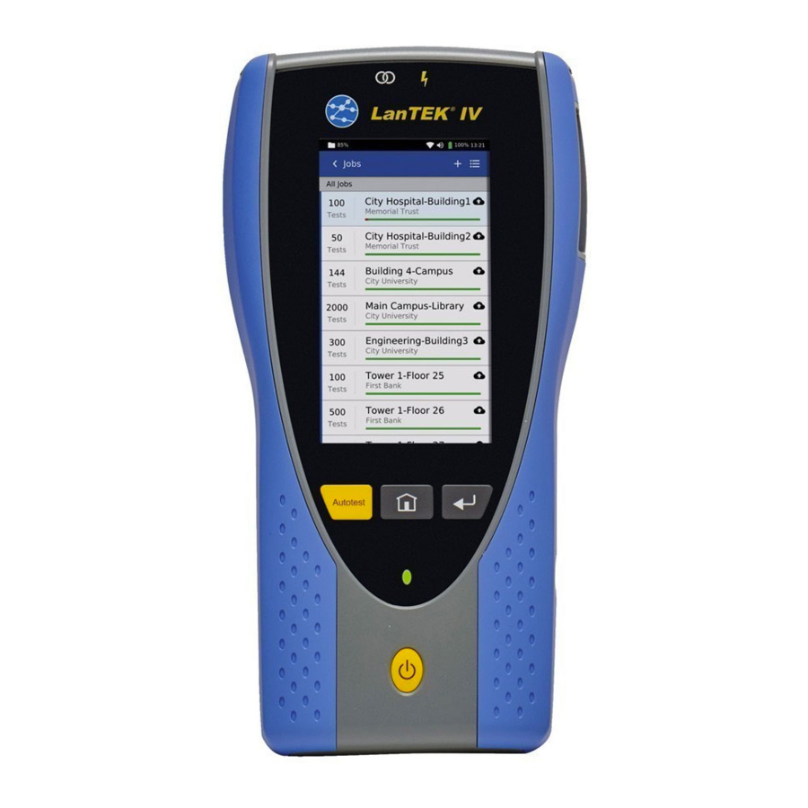
Jobs management and synchronization Manage Jobs Press JOBS to view the list jobs. Sort the list of jobs alphabetically. Sort jobs by creation date. Select multiple jobs. Create a new job. Proof of Performance... - Page 52 Job management and synchronization Long-press a job to open the options menu. The active job cannot be deleted. To delete the active job, first long-press the name of a different job to open the options menu. Press Set as current job to make it the active job.
- Page 53 Press SYNC to open the import & export synchronization options screen. Import transfers files and tests to be done from AnyWARE Cloud or Desktop to LanTEK IV for pre- configured tests in advance. Importing from AnyWARE Cloud checks the associated Cloud account and allows you to import all untested files or to select specific jobs to import.
-
Page 54: Folder Management And Synchronization
Wi-Fi. Selecting this option will synchronize all folders and tests not previously synchronized with the Cloud account associated to the LanTEK IV. Press “Upload to AnyWARE Cloud” to synchronize all tests to the Cloud software. Wi-Fi will turn on automatically if it is turned off when Upload to AnyWARE Cloud is selected. - Page 55 Folder management and synchronization Synchronization complete with the number of tests transferred. USB flash drive key requirements: Supported format - FAT32 Supported size - up to 512GB Storage capacity: Cat 6A/Class EA tests - 4000 tests per GB of storage space Cat 8/Class I/II tests - 2000 tests per GB of storage space Proof of Performance...
-
Page 56: Technical Specifications Of Cable Certifiers
Technical specifications of cable certifiers LanTEK IV-500: Ref. R163000 - 500MHz LanTEK IV-3000: Ref. R163001 - 3000MHz Batteries • Removable, interchangeable, rechargeable Lithium-Ion, 7.4V, 6.6Ah, 48.8Wh. • Charge time - 8 hours in handset, 4 hours using external charging port. - Page 57 Field replaceable heads on RJ45 permanent link adapters, recommended replacement interval every 2000 insertions • RJ45 Channel: TIA Cat. 6A / ISO Class EA up to 500 MHz (LanTEK IV 500) • RJ45 Channel: TIA Cat. 8.1 / ISO Class I up to 2000 MHz (LanTEK IV 3000) •...
- Page 58 Measurement details • ETL verified to meet ANSI / TIA-1152-A Level 2G, IEC 61935-1 Level VI for 500 MHz and 3000 MHz models User selectable optional measurements • TCL, ELTCTL, resistance unbalance • Time Domain NEXT - to locate distance to crosstalk events •...
- Page 59 • Devices: CE, C-Tick, FCC Part 15, Class A • Batteries: DOT 49 CFR 173.185, UN Part IV - section 38.3 Notes: Proof of Performance...
- Page 60 Stokenchurch House, Oxford Road, Stokenchurch, High Wycombe, Buckinghamshire, HP14 3SX, UK. Phone. +44 (0) 1925 428 380 | Fax. +44 (0) 1925 428 381 IDEAL NETWORKS, LanTEK, FiberTEK, uksales@idealnwd.com Specification subject to change without notice. VisiLINQ and the IDEAL AnyWARE logos E&OE...
Need help?
Do you have a question about the LanTEK IV and is the answer not in the manual?
Questions and answers