Fantech DBF110 Installation Instructions
Dryer exhaust booster system
Hide thumbs
Also See for DBF110:
- Installation instructions manual (13 pages) ,
- Installation and operation manual (17 pages) ,
- Installation instructions manual (13 pages)
Table of Contents
Advertisement
Quick Links
DBF110 DRYER EXHAUST BOOSTER SYSTEM
INSTALLATION INSTRUCTIONS
Positive Pressure Sensor Fan Proving Switch and Fan
DBF110 Kit Includes:
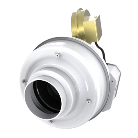
1 FR110 Inline Fan
1 DB10 Switch with Integral Delay
1 Fan Mounting Bracket and Hardware
IMPORTANT NOTICE: READ and SAVE THESE INSTRUCTIONS for FUTURE REFERENCE.
Installation Guidelines
IMPORTANT NOTICE! TO PREVENT THE POSSIBILITY OF DRYER
FAN CAVITATION AND/OR EXHAUSTING EXCESS HEAT REQUIRED
FOR THE DRYING CYCLE AND COMPROMISING DRYING TIMES,
BOOSTER FAN AIRFLOW MUST NOT EXCEED THE DRYER FAN
CAPACITY.
Please note: FR Series inline fans are not explosion proof. Do not use the fans if a
potentially explosive situation may exist.
Fan and Switch Mounting
The recommended location of the booster fan is a minimum of 15
linear (not equivalent) feet of duct from the dryer outlet. If the fan
is mounted closer than the recommended 15 feet, it may develop
enough pressure to lift wet lint into the fan impeller resulting in
excessive lint loading in the fan. The best location for the fan to be
mounted is as close as possible to the termination of the duct work.
Exception: If a secondary lint filter is installed between the dryer and
the booster fan, the booster fan may be mounted within the minimum
distance otherwise recommended (See illustration on left.)
An NB mounting bracket attached to a rafter or joist should be used to
stabilize the fan. Although not recommended, a vertical rigid duct may
support the fan if the duct is securely stabilized. (Consult local codes
prior to supporting the fan in the duct alone.) Duct work should be
attached to the inlet and outlet of the fan by means of vibration isolation
clamps or duct tape. The duct connection should be properly sealed to
prevent leakage and loss of fan performance. Flex duct connections
between the dryer duct connection and exhaust duct should be stretched
as smooth as possible.
Pressure Sensor Switch Operation
Fantech's DB10 is a positive pressure sensing switch which recognizes
dryer operation and activates the booster fan from an independent
electrical circuit. This eliminates connections through the dryer circuit
which may void the manufacturers' warranty as well as manual systems
which require the attention of the operator or costly current/temperature
sensing systems.
The electrical to the booster fan is connected in series through a
normally open terminal on the switch. A pressure tap is connected to a
tip on the side of the switch. When the dryer begins operation, positive
pressure in the duct causes the switch diaphragm to expand closing the
circuit to the booster fan. An integral delay-on-make timer in the switch
will cycle the fan on for intervals of 10 minutes. This will continue until
the dryer has stopped and the timer delay period has lapsed. Drying
cycles, the booster fan, the delay timer and the pressure switch are not
adversely affected by the starting/stopping intervals.
1712 Northgate Blvd. - Sarasota, FL. 34234
Phone: (800) 747-1762 Fax: (800) 487-9915
Phone: (941) 351-2947 Fax: (941) 3593828
Web Site www.fantech-us.com
DBF110599R
Advertisement
Table of Contents

Related Manuals for Fantech DBF110


Summary of Contents for Fantech DBF110
- Page 1 Pressure Sensor Switch Operation Fantech’s DB10 is a positive pressure sensing switch which recognizes dryer operation and activates the booster fan from an independent electrical circuit. This eliminates connections through the dryer circuit which may void the manufacturers’...
- Page 2 DBF110 FAN/SWITCH INSTALLATION INSTRUCTIONS Fan Installation Step 1. Selecting Fan Location If the fan is mounted Fan must be mounted a minimum of 15 feet from the dryer outlet. closer than the recommended 15 feet, it may develop enough pressure to lift wet lint into the fan impeller resulting in excessive lint loading in the fan.
- Page 3 Electrical Connection DO NOT CONNECT POWER SUPPLY UNTIL FAN IS COMPLETELY INSTALLED. MAKE SURE ELECTRICAL SERVICE TO THE FAN IS LOCKED IN "OFF" POSITION. 1. This unit has rotating parts and safety precautions should be exercised during installation, operation and maintenance. 2.
- Page 4 FANTECH, INC. will replace any product which has a factory defect in workmanship or material. Improper Maintenance, Product may be returned to either the point of purchase or the FANTECH factory, together with Bill of Misuse, abuse, abnormal use, or accident, or Sale, for an immediate replacement.
Need help?
Do you have a question about the DBF110 and is the answer not in the manual?
Questions and answers
The fan starts as it should but no longer shuts off after drying cycle
The Fantech DBF110 fan may not shut off after the drying cycle if the pressure switch is not functioning correctly. One possible cause is that the pressure switch diaphragm is not in the correct vertical position, which can affect its operation. Another potential issue could be a fault in the pressure switch itself, causing it to stay activated even when airflow from the dryer has stopped.
This answer is automatically generated