Advertisement
Table of Contents
- 1 Table of Contents
- 2 General
- 3 Application Information
- 4 Accessory Parts
- 5 Recommendation
- 6 Furnace in Upflow Position
- 7 Furnace in Downflow Position
- 8 Furnace in Horizontal Right Position
- 9 Furnace in Horizontal Left Position
- 10 Metering Device
- 11 Maximum Airflow Setting, CFM
- 12 Installing / Brazing Refrigerant Lines
- 13 Leak Check
- 14 Condensate Drain Piping
- 15 Outline Drawings
- 16 Troubleshooting Indoor TXV / Cooling Mode
- Download this manual
Installer's Guide
Cased Aluminum "Convertible" Coils
Models:
A4MXA1824AC6HA
A4MXB1832AC6HA
A4MXA3036AC6HA
A4MXB3642AC6HA
A4MXC3642AC6HA
ALL phases of this installation must comply with NATIONAL, STATE AND LOCAL CODES
IMPORTANT - This Document is customer property and is to remain with this unit. Please return to service informa-
tion pack upon completion of work.
WARNING
!
WARNING (Medium/high pressure)
Contains Refrigerant!
System contains oil and refrigerant under high pressure.
Recover refrigerant to relieve pressure before opening the
system. See unit nameplate for refrigerant type. Do not use
non-approved refrigerants, refrigerant substitutes, or refriger-
ant additives.
Failure to follow proper procedures or the use of non-approved
refrigerants, substitutes, or refrigerant additives could result
in death, serious injury, or equipment damage.
!
WARNING
This product can expose you to chemicals including lead,
which are known to the State of California to case cancer
and birth defects or other reproductive harm. For more
information go to www.P65Warnings.ca.gov
A. GENERAL
These coils are designed for use in combination with a heat pump
or cooling outdoor section using R-410A REFRIGERANT.
The A4MX equipment has been evaluated in accordance with
the Code of Federal Regulations, Chapter XX, Part 3280 or the
equivalent, "Suitable for Mobile Home use." The height of the
Furnace, Coil and discharge duct work must be 7 ft. or less.
Inspect the coil for shipping damage. Notify the transporta-
tion company immediately if the coil is damaged.
B. APPLICATION INFORMATION
1. FURNACE AND COIL
The coil MUST BE installed downstream (in the outlet air)
of the furnace.
2. INDOOR UNIT AIRFLOW
Indoor unit must provide the required airflow for the heat
pump or cooling combinations approved for these coils.
A4MXB4248AC6HA
A4MXC4248AC6HA
A4MXD4248AC6HA
A4MXC4260AC3HA
A4MXD4260AC3HA
Table of Contents
General ............................................................................... 1
Application Information ................................................ 1
Accessory Parts ................................................................ 2
Recommendation ............................................................. 2
Furnace in Upflow Position .......................................... 2
Furnace in Downflow Position ..................................... 3
Furnace in Horizontal Right Position ........................ 4
Furnace in Horizontal Left Position ........................... 5
Metering Device ............................................................... 6
Maximum Airflow Setting, CFM ................................... 7
Installing / Brazing Refrigerant Lines ....................... 7
Leak Check........................................................................ 8
Condensate Drain Piping .............................................. 8
Outline Drawings ............................................................ 9
Troubleshooting Indoor TXV / Cooling Mode ......... 10
NOTE:
OPTIONAL DOWNFLOW GASKET INSTALLATION: For
unusually humid applications that expect prolonged
operation above 70% RH, it is recommended to use the
BAYGSKT001A0 gasket kit to prevent water from forming
on the bottom of the drain pan and dripping into the sup-
ply ductwork.
18-AD37D1-1-EN
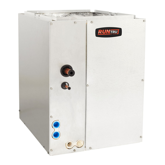
Figure 1
IMPORTANT: Review your installation requirements. Check
the table on the outline drawings and note all dimensions
for your coil before beginning the installation.
Advertisement
Table of Contents

Related Manuals for Trane A4MXA1824AC6HA


Summary of Contents for Trane A4MXA1824AC6HA
-
Page 1: Table Of Contents
18-AD37D1-1-EN Installer’s Guide Cased Aluminum "Convertible" Coils Models: A4MXB4248AC6HA A4MXA1824AC6HA A4MXC4248AC6HA A4MXB1832AC6HA A4MXD4248AC6HA A4MXA3036AC6HA A4MXC4260AC3HA A4MXB3642AC6HA A4MXD4260AC3HA A4MXC3642AC6HA ALL phases of this installation must comply with NATIONAL, STATE AND LOCAL CODES IMPORTANT — This Document is customer property and is to remain with this unit. Please return to service informa- tion pack upon completion of work. -
Page 2: Accessory Parts
S-series furnaces, bend furnace duct flanges outward for cased coil alignment. Drill screws into furnace duct flange though clearance alignment holes located near bottom of coil cabinet. The coil is always placed downstream of the fur- nace airflow. 18-AD37D1-1-EN © Trane 2019 All rights reserved. -
Page 3: Furnace In Downflow Position
Installer’s Guide F. FURNACE IN DOWNFLOW POSITION 1. DOWNFLOW COIL CONVERSION: While not required, optional removal of some coil components will maximize airflow efficiency. a. Remove the coil by sliding the coil out of the coil enclo- sure. Start here b. -
Page 4: Furnace In Horizontal Right Position
Installer’s Guide G. FURNACE IN HORIZONTAL RIGHT POSITION CAUTION Both the coil and furnace must be fully supported. Do not attempt to suspend the coil using the brackets. Note: when installing onto an S-Series furnaces in horizontal right or downflow configuration the flanges will be bent downward. -
Page 5: Furnace In Horizontal Left Position
Installer’s Guide H. FURNACE IN HORIZONTAL LEFT POSITION CAUTION Both the coil and furnace must be fully supported. Do not attempt to suspend the coil using the brackets. 1. HORIZONTAL LEFT COIL CONVERSION: S-Series upflow furnaces can be horizontal left or right. For legacy furnaces, the non-condensing furnaces may be laid on either side for horizontal application. -
Page 6: Metering Device
Factory Included Metering Device COIL MODEL NOMINAL FACTORY ADDITIONAL TONS INSTALLED INCLUDED Note: Install the orifice ORIFICE ORIFICE in the orientation SIZE SIZES shown. A4MXA1824AC6HA 0.057 0.052 A4MXB1832AC6HA 0.052, 0.064 A4MXA3036AC6HA 0.064 0.068 A4MXB3642AC6HA 0.068 0.077 A4MXC3642AC6HA 0.077 A4MXB4248AC6HA 0.077 0.082... -
Page 7: Maximum Airflow Setting, Cfm
Maximum airflow setting, CFM Coil Upflow Horizontal Left 1. The following steps are to be considered when installing A4MXA1824AC6HA the refrigerant lines: A4MXB1832AC6HA 1125 1000 a. Determine the most practical way to run the lines. -
Page 8: Leak Check
Installer’s Guide Capillary tubes will come out the top of bulb when positioned correctly. Figure 12 When replacing the bulb and bulb clip, reinstall the bulb in the proper orientations. See Figure 12. 9. For models with a TXV, wrap the TXV with insulation after the bulb clip has been installed. -
Page 9: Outline Drawings
Installer’s Guide 18-AD37D1-1-EN... -
Page 10: Troubleshooting Indoor Txv / Cooling Mode
Installer’s Guide Before starting, insure the blower wheel, indoor and outdoor Troubleshooting Indoor TXV / Cooling Mode coils are clean. Correct air Is sub cooling at the Is superheat Is air flow at least flow outdoor unit between < 5F? 350 CFM per ton? problem 8 to 12F? - Page 11 Installer’s Guide 18-AD37D1-1-EN...
- Page 12 Trane 06/19 6200 Troup Highway Tyler, TX 75707 Since the manufacturer has a policy of continuous product and product data improvement, it reserves the For more information contact right to change design and specifications without notice. your local dealer (distributor)
Need help?
Do you have a question about the A4MXA1824AC6HA and is the answer not in the manual?
Questions and answers