Table of Contents
Advertisement
Available languages
Available languages
Quick Links
Advertisement
Chapters
Table of Contents

Subscribe to Our Youtube Channel
Related Manuals for Lamborghini Caloreclima RUBINO PLUS


Summary of Contents for Lamborghini Caloreclima RUBINO PLUS
- Page 1 DIAMANT M RUBINO PLUS Monosplit DC inverter in pompa di calore Monosplit DC inverter in heat pump Monosplit DC-inverter in warmtepomp MANUALE INSTALLAZIONE E MANUTENZIONE USE AND MAINTENANCE MANUAL INSTALLATIE- EN ONDERHOUDSHANDLEIDING Cod. 3QE46190 - Rev. 01 - 10/2020...
-
Page 2: Table Of Contents
RUBINO PLUS 1. CARATTERISTICHE GENERALI ..................3 1.1 RICEVIMENTO........................3 1.2 PREMESSA ...........................3 1.3 PRESENTAZIONE DELLE UNITÀ ..................3 1.4 DIRETTIVE EUROPEE ......................3 1.5 Dati tecnici ..........................4 1.6 DIMENSIONI DI INGOMBRO ....................4 1.7 DESCRIZIONE UNITÀ ......................5 1.8 NORME DI SICUREZZA .......................6 2. INSTALLAZIONE ....................... 7 2.1 IMBALLO E IMMAGAZZINAMENTO..................7... -
Page 3: Caratteristiche Generali
RUBINO PLUS 1. CARATTERISTICHE GENERALI 1.1 RICEVIMENTO Al momento del ricevimento dell'unità è indispensabile controllare di aver ricevuto tutto il materiale indicato sul documento d'accom- pagnamento, ed inoltre che la stessa non abbia subito danni durante il trasporto. In caso affermativo, far costatare allo spedizioniere l'entità... -
Page 4: Dati Tecnici
RUBINO PLUS 1.5 DATI TECNICI UNITA’ INTERNA MURALE Alimentazione 230/1/50 230/1/50 230/1/50 230/1/50 230/1/50 V-F-Hz Resa Frigorifera* 2050 2640 3520 5275 7035 Resa Termica* 2350 2930 3810 5570 7330 Portata aria unità interna 460/330/260 460/330/260 530/400/350 800/600/500 1090/770/610 (Max-med-min) Pressione sonora unità interna**... -
Page 5: Descrizione Unità
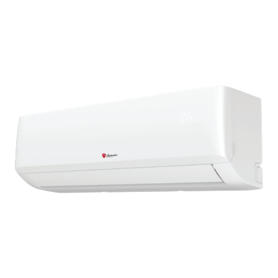
RUBINO PLUS 1.7 DESCRIZIONE UNITÀ 1 - "fig. 2 -". MOBILE DI COPERTURA Il mobile di copertura è interamente in ABS e funge anche da struttura portante. 2 - "fig. 2 -". GRUPPO VENTILANTE Il gruppo ventilante è composto da un ventilatore tangenziale. -
Page 6: Norme Di Sicurezza
RUBINO PLUS 1.8 NORME DI SICUREZZA Le norme sottoindicate vanno seguite attentamente per evitare danni all'operatore e alla macchina. • L’installazione della macchina deve essere eseguita secondo le norme di impiantistica nazionale • Il presente manuale dell'installatore, il manuale dell'utente e gli schemi elettrici sono parte integrante della macchina. Tutti insieme devono essere custoditi e conservati con cura affinché... -
Page 7: Installazione
RUBINO PLUS 2. INSTALLAZIONE 2.1 IMBALLO E IMMAGAZZINAMENTO Tutti i modelli sono provvisti d'appositi imballi in cartone specifici per ogni unità. Sugli imballi sono riportate tutte le indicazioni necessarie per una corretta movimentazione durante l'immagazzinamento e la messa in opera. - Page 8 RUBINO PLUS Unità esterna posta in alto e unità interna in basso ("fig. 5 -"). In questo caso, in particolare sulle unità mono split, sulla tubazione d'aspirazione devono essere previsti dei sifoni secondo quanto indicato nello schema riportato sul manuale di installazione delle unità esterne. Questi sifoni avranno lo scopo di rendere possibile il ritorno dell'olio al compressore.
- Page 9 RUBINO PLUS La procedura di installazione dell’unità interna è riassunta graficamente "fig. 6 -": fig. 6 - 1: scelta del luogo di installazione 2-3: fissaggio della piastra di supporto 4: realizzazione del foro di passaggio attraverso la parete 5: collegamento delle tubazioni...
-
Page 10: Installazione Dell'unita' Interna
RUBINO PLUS 2.3 INSTALLAZIONE DELL’UNITA’ INTERNA Scelta del luogo di Installazione. Nel rispetto delle condizioni evidenziate nella sezione "Schemi di Installazione", riportato nel ma- nuale delle unità esterne. Posizionare l'unità il più basso possibile, garantendo comunque i 15cm di spazio libero al di sopra dell'unità. - Page 11 RUBINO PLUS Mod. 18 Sagoma unità interna fig. 10 - Mod. 24 Sagoma unità interna fig. 11 - Procedere come di seguito riportato: Posizionare la piastra sulla parete all'altezza opportuna e fissarla mantenendola il più orizzontale possibile (usare una livella).
-
Page 12: Opzioni Di Installazione
RUBINO PLUS 2.4 OPZIONI DI INSTALLAZIONE L'unità interna può essere installata anche nelle seguenti posizioni: 1. Con uscita lateralmente a destra. 2. Con uscita dietro 3. Con uscita lateralmente a sinistra. Per eseguire installazioni con uscite dietro a sinistra procedere come indicato in seguito: 1. -
Page 13: Collegamenti Frigoriferi
RUBINO PLUS 2.6 COLLEGAMENTI FRIGORIFERI Per collegare le linee frigorifere procedere come indicato di seguito ("fig. 18 -"): • Far combaciare le estremità del tubo cartellato precedentemente con quelle degli attacchi posti sulle unità interne • Avvitare a mano il bocchettone e quindi serrarlo con l’ausilio di un chiave adeguata (per evitare tensioni sulle tubazioni è consigliabile agire con una controchiave). -
Page 14: Isolamento Tubazioni
RUBINO PLUS 2.8 ISOLAMENTO TUBAZIONI E’ opportuno per garantire l’efficienza del sistema ed il suo corretto funzionamento che vengano utilizzate linee di collegamento fri- gorifero pre-isolate, comunemente reperibili in commercio. Si raccomanda inoltre di fare attenzione ai punti di collegamento secondo quanto descritto. -
Page 15: Messa In Funzione
RUBINO PLUS 3. MESSA IN FUNZIONE 3.1 PRIMO AVVIAMENTO Prima di eseguire il primo avviamento, prima di avviare l'impianto per il lavoro stagionale o dopo una lunga sosta è necessario ese- guire i seguenti controlli preliminari che riguardano la parte elettrica e la parte frigorifera. - Page 16 RUBINO PLUS 1. GENERAL SPECIFICATIONS ..................17 1.1 CONSIGNMENT OF THE MACHINE ..................17 1.2 FOREWORD ........................17 1.3 PRESENTATION OF THE UNIT..................17 1.4 DECLARATION OF CONFORMITY ..................17 1.5 TECHNICAL DATA ......................18 1.6 OVERALL DIMENSIONS ....................18 1.7 UNITDESCRIPTION ......................19 1.8 SAFETY REGULATIONS ....................20 2.
-
Page 17: General Specifications
RUBINO PLUS 1. GENERAL SPECIFICATIONS 1.1 CONSIGNMENT OF THE MACHINE As soon as the machine is consigned, it is essential for the user to make sure that he has received all the items indicated on the consignment note and that the machine has not been damaged during transport. If damage is discovered, allow the forwarding agent to ascertain its entity and also inform our seller. -
Page 18: Technical Data
RUBINO PLUS 1.5 TECHNICAL DATA MODEL Power Supply 230/1/50 230/1/50 230/1/50 230/1/50 230/1/50 V-F-Hz Cooling Capacity* 2050 2640 3520 5275 7035 Heating Capacity * 2350 2930 3810 5570 7330 Outdoor unit air flow 460/330/260 460/330/260 530/400/350 800/600/500 1090/770/610 (Max-med-min) Sound pressure level outdoor unit **... -
Page 19: Unitdescription
RUBINO PLUS 1.7 UNITDESCRIPTION 1 - "fig. 2 -". CABINET FOR THE WALL INDOOR UNIT The cabinet housing the wall indoor unit is entirely made of ABS and also acts as a bearing structure. 2 - "fig. 2 -". VENTILATING UNIT The ventilating unit of the wall unit consists of a tangential fan. -
Page 20: Safety Regulations
RUBINO PLUS 1.8 SAFETY REGULATIONS Strictly comply with the following regulations to prevent injury to the operator or damage to the machine. • The unit installation must be done according to the installation rules valid in your country. • This installer's handbook, the user manual and the wiring diagrams are integral part of the machine.They must be kept with care and be ready to hand should the operators require them for consultation. -
Page 21: Installation
RUBINO PLUS 2. INSTALLATION 2.1 PACKING AND STORING All machines are packed in cardboard boxes specific for each unit. The indications required to correctly handle the appliance while storing and installing it are written on the packing. The storage temperature must be between -25°C and 55°C. - Page 22 RUBINO PLUS Outdoor unit positioned on top and indoor unit on the bottom ("fig. 5 -"). In this case, in particular on mono split units, the suction line must have traps as indicated in the diagram in the installation manual of the outdoor units.The connection piping must be insulated.
- Page 23 RUBINO PLUS The installation is summarised in the following figures "fig. 6 -": fig. 6 - 1: select installation location 2-3: attach mounting plate 4: drill wall hole 5: connect piping 6: connect wiring 7: prepare drain hose 8: wrap piping and cable 9: mount indoor unit Cod.
-
Page 24: Installing The Indoor Unit
RUBINO PLUS 2.3 INSTALLING THE INDOOR UNIT Choice of place of installation. In compliance with the conditions indicated in the "Installation Diagrams" section, reported in the ma- nual of the outdoor units. position the unit as low as possible, leaving 15 cm of free space over the unit. It is recommended to observe the spaces indicated in the figure "fig. - Page 25 RUBINO PLUS Mod. 18 Shape internal unit fig. 10 - Mod. 24 Shape internal unit fig. 11 - Proceed as follows: Position the plate on the wall at a suitable height and fix it in place keeping it as level as possible (use a spirit level).
-
Page 26: Installation Option
RUBINO PLUS 2.4 INSTALLATION OPTION The indoor unit may also be installed in the following positions: 1. With side outlet to the right. 2. With outlet facing downwards 3. With side outlet to the left. To install the unit with rear outlet to the left, proceed as indicated below: 1. -
Page 27: Refrigerant Connections
RUBINO PLUS 2.6 REFRIGERANT CONNECTIONS To connect the refrigerant lines, proceed as follows ("fig. 18 -"): • Match the ends of the previously flared pipe with those of the connections on the indoor units • Screw the union by hand and then tighten it with a suitable wrench (to avoid tension on the pipes it is advisable to also use a second wrench). -
Page 28: Pipe Insulation
RUBINO PLUS 2.8 PIPE INSULATION In order to ensure the system efficiency and its correct operation, it is necessary to use pre-insulated cooling connection lines easily available on the market.Pay also attention to the connection points according to what described. -
Page 29: Setting And Work
RUBINO PLUS 3. SETTING AND WORK 3.1 STARTING UP FOR THE FIRST TIME Before starting the unit for the first time, before starting the system for seasonal work or after a long period at a standstill, carry out the following preliminary inspections with regard to the electrical and cooling parts. - Page 30 RUBINO PLUS 1. ALGEMENE KENMERKEN ..................... 31 1.1 INONTVANGSTNEMING VAN DE MACHINE ..............31 1.2 PRESENTATIE ........................31 1.3 PRESENTATIE VAN DE UNIT ....................31 1.4 VERKLARING VAN OVEREENSTEMMING ...............31 1.5 TECHNISCHE GEGEVENS ....................32 1.6 BUITENAFMETINGEN ......................32 1.7 COMPONENTEN BINNENUNIT ..................33 1.8 VEILIGHEIDSVOORSCHRIFTEN ..................34 2.
-
Page 31: Algemene Kenmerken
RUBINO PLUS 1. ALGEMENE KENMERKEN 1.1 INONTVANGSTNEMING VAN DE MACHINE Controleer bij de inontvangstneming van de unit of u alle materialen die in het bijgaande document zijn vermeld hebt ontvangen en of de unit geen schade heeft geleden tijdens het transport. Indien dit wel het geval is, laat de transporteur dan de omvang van de geleden schade vaststellen en waarschuw ondertussen onze klantenbeheerafdeling. -
Page 32: Technische Gegevens
RUBINO PLUS 1.5 TECHNISCHE GEGEVENS MODEL Stroomvoorziening 230/1/50 230/1/50 230/1/50 230/1/50 230/1/50 V-F-Hz Koelcapaciteit * 2050 2640 3520 5275 7035 Verwarmingscapaciteit * 2350 2930 3810 5570 7330 Luchtstroom 460/330/260 460/330/260 530/400/350 800/600/500 1090/770/610 (Max-med-min) Geluidsdrukniveaut ** 37/32/22 37/32/22 37/32/22 41/37/31... -
Page 33: Componenten Binnenunit
RUBINO PLUS 1.7 COMPONENTEN BINNENUNIT 1- "Fig. 2 -". AFDEKKAST De afdekkast bestaat volledig uit ABS en fungeert ook als dra- agconstructie. 2- "Fig. 2 -". VENTILATIEGROEP De ventilatiegroep wordt gevormd door een dwarsstroomventila- tor. Dit maakt een zeer stille werking mogelijk. De motor is een borstelloze gelijkstroommotor 3- "Fig. -
Page 34: Veiligheidsvoorschriften
RUBINO PLUS 1.8 VEILIGHEIDSVOORSCHRIFTEN Onderstaande voorschriften moeten aandachtig worden opgevolgd om letsel en schade te voorkomen. • De installatie van de machine moet volgens de nationale installatienormen worden verricht • Deze handleiding van de installateur, de gebruikershandleiding en de schakelschema's zijn een essentieel onderdeel van de machine. -
Page 35: Installatie
RUBINO PLUS 2. INSTALLATIE 2.1 VERPAKKING EN OPSLAG Alle modellen zijn verpakt in voor elke unit specifiek karton. Op de verpakkingen zijn aanwijzingen aangebracht voor een correcte hantering tijdens de opslag en de inwerkingstelling. De op- slagtemperatuur moet tussen -25°C en 55°C liggen. - Page 36 RUBINO PLUS Buitenunit hoog en binnenunit laag geplaatst ("Fig. 5 -"). In dit geval moeten er met name op de mono split-units sifons op de zuigleiding worden aangebracht volgens de aanwijzingen in het schema in de installatiehandleiding van de buitenunits. Deze sifons zijn bedoeld om terugloop van olie naar de compressor mogelijk te maken.
- Page 37 RUBINO PLUS De installatieprocedure van de binnenunit is grafisch samengevat in de volgende afbeelding "Fig. 6 -": Fig. 6 - 1: keuze van de plaats van installatie 2-3: bevestiging van de steunplaat 4: constructie van het doorvoergat door de muur...
-
Page 38: Installatie Van De Binnenunit
RUBINO PLUS 2.3 INSTALLATIE VAN DE BINNENUNIT Keuze van de installatieplaats. Met inachtneming van de omstandigheden beschreven in het deel "Installatieschema’s", te vinden in de handleiding van de buitenunits. Plaats de unit zo laag mogelijk, in ieder geval met 15 cm vrije ruimte boven de unit. Geadviseerd wordt om de aangegeven ruimten aan te houden ("Fig. - Page 39 RUBINO PLUS Mod. 18 Sagoma unità interna Fig. 10 - Mod. 24 Sagoma unità interna Fig. 11 - Ga als volgt te werk: Zet de plaat op de juiste hoogte tegen de wand en bevestig hem door hem zo horizontaal mogelijk te houden (gebruik een waterpas).
-
Page 40: Installatie-Opties
RUBINO PLUS 2.4 INSTALLATIE-OPTIES De binnenunit kan ook in de volgende posities worden geïnstalleerd: 1. Met de uitlaat aan de rechterzijde. 2. Met de uitlaat aan de achterzijde. 3. Met de uitlaat aan de linkerzijde. Ga als volgt te werk om de installaties uit te voeren met de uitlaat links achter: 1. -
Page 41: Koelaansluitingen
RUBINO PLUS 2.6 KOELAANSLUITINGEN Ga als volgt te werk om de koelleidingen aan te sluiten: • Laat de uiteinden van de eerder opgetrompte leiding ("Fig. 18 -") samenvallen met de aansluitingen op de binnenunits. • Draai met de hand de koppelmof vast en haal hem vervolgens aan met een geschikte sleutel (om spanningen op de leidingen te vermijden, is het raadzaam om een contrasleutel te gebruiken). -
Page 42: Pijpisolatie
RUBINO PLUS 2.8 PIJPISOLATIE Om de efficiëntie van het systeem en de juiste werking ervan te waarborgen, is het raadzaam om vooraf geïsoleerde koelkastaanslu- Het wordt ook aanbevolen om aandacht te besteden aan itleidingen te gebruiken, die gewoonlijk op de markt verkrijgbaar zijn. -
Page 43: Inwerkingstelling
RUBINO PLUS 3. INWERKINGSTELLING 3.1 EERSTE START Voor de eerste start of na een lange periode van stilstand moeten eerst de volgende controles worden uitgevoerd op het elektrische deel en het koelgedeelte, alvorens de installatie voor het seizoen te starten. - Page 44 LAMBORGHINI Caloreclima è un marchio del gruppo FERROLI Spa 37047 San Bonifacio (Verona) Italy ¬ Via Ritonda 78/A ¬ tel. +39.045.6139411 ¬ fax +39.045.6100933 www.ferroli.com Made in China Cod. 3QEXXXX - Rev. 00 -...
Need help?
Do you have a question about the RUBINO PLUS and is the answer not in the manual?
Questions and answers