Table of Contents
Advertisement
Available languages
Available languages
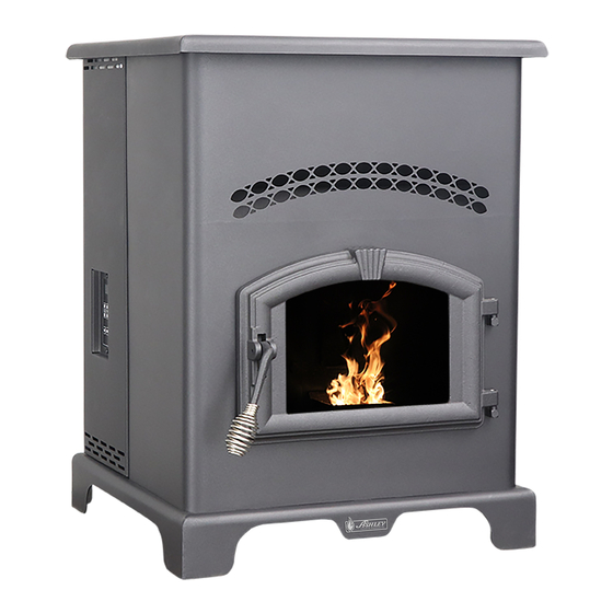
Owner's Operation and Instruction Manual
THIS MANUAL WILL HELP YOU TO OBTAIN EFFICIENT, DEPENDABLE SERVICE FROM THE HEATER, AND ENABLE YOU
TO ORDER REPAIR PARTS CORRECTLY. KEEP IN A SAFE PLACE FOR FUTURE REFERENCE.
• Please read this entire manual before installation and use of this
appliance. Failure to follow these instructions could result in property
damage, bodily injury, or even death.
• Contact your local building or fire officials about obtaining permits,
restrictions and installation inspection requirements in your area.
• Save these instructions.
• If your heater is not properly installed, a house fire may result. For
everyone's safety, follow all Installation and Operating Directions.
Never use makeshift compromises during the installation of this
appliance. Contact your local building or fire officials about
restrictions and installation inspection requirements in your area.
CALIFORNIA PROPOSITION 65 WARNING:
This product can expose you to chemicals including carbon monoxide, which
is known to the State of California to cause cancer, birth defects and/or other
reproductive harm. For more information, go to www.P65warnings.ca.gov
MODEL: AP130
SAVE THESE INSTRUCTIONS
United States Stove Company
227 Industrial Park Road
South Pittsburg, TN 37380
Report #: 215-S-05c-2
Certified to ASTM E 1509, 2012, and Certified to
ULC S627, 2000, and(UM) 84-HUD
This unit is not intended to be used as a
primary source of heat.
U.S. Environmental Protection Agency
Certified to comply with 2015 particulate
emissions standards.
853146B-2604H
Advertisement
Table of Contents

Subscribe to Our Youtube Channel
Related Manuals for Ashley AP130


Summary of Contents for Ashley AP130
- Page 1 Owner’s Operation and Instruction Manual MODEL: AP130 SAVE THESE INSTRUCTIONS THIS MANUAL WILL HELP YOU TO OBTAIN EFFICIENT, DEPENDABLE SERVICE FROM THE HEATER, AND ENABLE YOU TO ORDER REPAIR PARTS CORRECTLY. KEEP IN A SAFE PLACE FOR FUTURE REFERENCE. • Please read this entire manual before installation and use of this appliance.
-
Page 2: Safety Precautions
Safety Precautions This manual describes the installation and operation of the Ashley, AP130 pellet stove. away from all combustible materials, pending final • IMPORTANT: Read this entire manual before installing and operating this product. Failure to do disposal. • The exhaust system should be checked monthly so may result in property damage, bodily injury, or even death. -
Page 3: Specifications
Specifications HEATING SPECIFICATIONS 1.5 - 5.0 lbs./hr. (0.7 - 2.3 kg/hr) Fuel Burn Rate* Burn Time (lowest setting) 80 hrs. 130lbs. (59kg) Hopper Capacity * Pellet size may effect the actual rate of fuel feed and burn times. Fuel feed rates may vary by as much as 20%. Use PFI listed fuel for best results. -
Page 4: Installation
Installation Installation Options Read this entire manual before you install and use your pellet stove. Failure to follow instructions may result in property damage, bodily injury, or even death! (See specific installation details for clearances and other installation requirements) A Freestanding Unit—supported by pedestal/legs and placed on a non-combustible floor surface in compliance with clearance requirements for a freestanding stove installation. - Page 5 Installation CLEARANCES Your pellet stove has been tested and listed for installation in residential, mobile home, and alcove applications in accordance with the clearances given in TABLE 1. NOTE: Distance “B” on the side of your pellet stove may need to be greater than the minimum required clearance for suitable access to the control panel.
-
Page 6: Venting Requirements
Installation VENTING REQUIREMENTS • INSTALL VENT AT CLEARANCES SPECIFIED BY THE VENT MANUFACTURER. • DO NOT CONNECT THE PELLET VENT TO A VENT SERVING ANY OTHER APPLIANCE OR STOVE. • DO NOT INSTALL A FLUE DAMPER IN THE EXHAUST VENTING SYSTEM OF THIS UNIT. The following installation guidelines must be followed to ensure conformity with both the safety listing of this stove and to local building codes. -
Page 7: Vent Termination Clearances
Installation VENT TERMINATION CLEARANCES A. Minimum 4-foot (1.22m) clearance below or beside any door or window that opens. B. Minimum 1-foot (0.3m) clearance above any door or window that opens. C. Minimum 3-foot (0.91m) clearance from any adjacent building. D. Minimum 7-foot (2.13m) clearance from any grade when adjacent to public walkways. E. -
Page 8: Through The Wall Installation
Installation THROUGH THE WALL INSTALLATION (RECOMMENDED INSTALLATION) Canadian installations must conform to CAN/CSA-B365. To vent the unit through the wall, connect the pipe adapter to the exhaust motor adapter. If the exhaust adapter is at least 18 in.(457mm) above ground level, a straight section of pellet vent pipe can be used through the wall. -
Page 9: Outside Air Supply
Installation OUTSIDE AIR SUPPLY (OPTIONAL, UNLESS INSTALLING IN A MOBILE HOME) Depending on your location and home construction, outside air may be necessary for optimal performance. Metal pipe (solid or flexible) must be used for the outside air installation. PVC pipe is NOT approved and should NEVER be used. -
Page 10: Understanding Your Stove
Understanding Your Stove HOW YOUR STOVE WORKS 4 Digit Display Your pellet stove utilizes a inclined auger fuel feed system that is Figure 10 Digital Control Panel operated microprocessor controlled digital circuit board. The digital circuit board allows the Up / Down Buttons : inclined auger fuel feed system to run in a timer-based, non-continuous... -
Page 11: Control Panel Overview
Control Panel Overview Turning the heater ON/OFF, as well as adjustments for the fuel feed rate and room fan speed are performed by pressing the appropriate button(s) on the control panel which is located on the lower left-hand side of your heater. -
Page 12: Operation
Operation UNIT PREPARATION After carefully unpacking and reading the instructions for installing your stove, you will need to perform the following steps: • Attach the included spring handle to the door handle by screwing it on in a respective location. •... -
Page 13: Do Not Burn
Operation • DO NOT USE CHEMICALS OR FLUIDS TO START THE FIRE - Never use gasoline, gasoline-type lantern fuel, kerosene, charcoal lighter fluid, or similar liquids to start or “freshen up” a fire in this stove. Keep all such liquids well away from the stove while it is in use. •... -
Page 14: Shutdown Procedure
Operation First Fire: Adjust the “Heat Range” and “Blower Speed” to a “3” setting and allow the stove to operate in this manner for approximately three (3) hours (or more if necessary), allowing the stove to “cure out” as the paint and oils from the manufacturing process burn off. -
Page 15: Maintenance
Maintenance • Failure to clean and maintain this unit as indicated can result in poor performance and safety hazards. • Unplug your stove’s electrical cord prior to removing the back panel or opening the exhaust system for any inspection, cleaning, or maintenance work. •... -
Page 16: Chimney Connector
Maintenance CHECK AND CLEAN THE HOPPER Check the hopper periodically to determine if there is any sawdust or pellets that are sticking to the hopper surface. Clean as needed. DOOR AND GLASS GASKETS Inspect the main door and glass window gaskets periodically. The main door may need to be removed to have frayed, broken, or compacted gaskets replaced by your authorized dealer. -
Page 17: Troubleshooting
Trouble Shooting • Disconnect the power cord before performing any maintenance! NOTE: Turning the ON/OFF Switch to ”OFF” does not disconnect all power to the electrical components of the stove. • Never try to repair or replace any part of the stove unless instructions for doing so are given in this manual. All other work should be done by a trained technician. -
Page 18: Display Indicators
DISPLAY INDICATORS Several situations or events are indicated in normal operation by blinking display indicators or segments in the display: Flashing On Indicator: This means that the stove is in the “Start Up” state waiting for the ignition procedure to complete. - Page 19 BLACK GRAY Insure the wires are connected to the bottom two prongs of the hopper switch as shown. CORRECT WRONG...
-
Page 20: Parts List
Parts List 89586 Part No. Description Qty. Nipple 69524 891121 3” Feed Door Assembly Silicone Hose 891372 83537 Door Hinge Pad Hose Clamp (#4) 25080B 88119 Feed Door Latch Insulation Blanket 69693 Burnpot Housing Gasket Burnpot Housing Weldment 88168 26096MB Hearth 86624 Burnpot Assembly 25513... -
Page 22: Service Record
Service Record It is recommended that your heating system is serviced regularly and that the appropriate Service Interval Record is completed. SERVICE PROVIDER Before completing the appropriate Service Record below, please ensure you have carried out the service as described in the manufacturer’s instructions. Always use the manufacturer's specified spare part when replacement is necessary. -
Page 23: Limited Warranty
Limited Warranty instructions; (7) installation or use of components not supplied with appliance The operation of this unit in a manner inconsistent with the owner’s manual or any other components not expressly authorized and approved by USSC; (8) will void the warranty and is also against federal regulations. United States modification of the appliance not expressly authorized and approved by USSC Stove Company warrants this product to be free from defects in material and workmanship, to the original retail purchaser only, for the time period identified... - Page 24 How to Order Repair Parts / Comment commander des pièces détachées This manual will help you obtain efficient, dependable service from your heater, and enable you to order repair parts correctly. Keep this manual in a safe place for future reference. When writing, always give the full model number which is on the nameplate attached to the heater.
- Page 25 Garantie limitée des ventilateurs de tirage, des chaudières à air pulsé ou toute autre cause; (6) L’utilisation de cette unité en contradiction avec le manuel de l’utilisateur annulera la garantie, tout en enfreignant les règlementations fédérales. United States Stove l’utilisation de combustibles autres que ceux mentionnés dans les instructions d’utilisation;...
- Page 26 Enregistrement De Service Il est recommandé que votre système de chauffage est desservi régulièrement et que le Service Interval enregistrement approprié est terminée. FOURNISSEUR DE SERVICES Avant de terminer l’enregistrement de service approprié ci-dessous, s’il vous plaît vous assurer que vous avez effectué...
- Page 27 Nomenclature 25774 Clé Réf La description Qté. Pressostat Support 69524 80549 Montage D'alimentation De Porte Commutateur De Pression 891372 89586 Charnière De Porte Pad Mamelon 25080B 891121 Nourrissez Loquet De Porte Tuyau De Silicone 83537 Logement Weldment Pot De Collier De Serrage (N ° 4) 69693 Combustion 88119...
- Page 29 MOTEUR BLANC D'ENTRAÎNEMENT DE LA VIS SANS FIN SOUFFLANTE DE DISTRIBUTION NOIR BLANC MICRORUPTEUR PRESSOSTAT NOIR PRISE MOLEX AU CIRCUIT IMPRIMÉ BLANC MARRON NOIR MARRON GRIS ALLUMEUR VENTILATEUR D'ÉVACUATION PRINCIPAL SOURCE ÉLECTRIQUE THERMISTOR ALLUMEUR BLANC NOIR Assurez-vous fils sont connectés deux broches inférieures de l’interrupteur de la...
- Page 30 Codes d’erreur et indicateurs d’affichage Code d’erreur Description de l’erreur Causes possibles • Ventilation inadéquate. Le capteur de limite élevée de température s’est • Panne du ventilateur de la pièce. Err1 déclenché. • Blocage de l’évacuation. • Circuit électrique ouvert. •...
-
Page 31: Dépannage
Dépannage • Déconnectez le cordon d'alimentation avant d'effectuer tout travail d'entretien ! REMARQUE: Mettre l'interrupteur ON/OFF (marche/arrêt) sur "OFF" ne coupe pas l'alimentation des composants électriques du poêle. • Ne tentez jamais de réparer ou de remplacer une pièce du poêle à moins que des instructions pour le faire ne soient fournies dans ce manuel. -
Page 32: Entretien
Entretien JOINTS DE LA PORTE ET DE LA VITRE Inspectez périodiquement les joints de la porte principale et de la fenêtre vitrée. Il se peut qu’il soit nécessaire de retirer la porte principale pour que votre revendeur autorisé remplace les joints éraillés, cassés ou compactés. Le joint de la vitre possède un vide dans sa partie inférieure destiné... - Page 33 Entretien • Le fait de ne pas nettoyer ni entretenir cette unité tel qu'indiqué peut entraîner des performances faibles et des risques pour la sécurité. • Débranchez le cordon électrique de votre poêle avant de retirer le panneau arrière ou d'ouvrir le système d'aspiration pour toute inspection, ou tout travail de nettoyage ou d'entretien.
-
Page 34: Procédure D'arrêt
Fonctionnement PROCÉDURE D'ARRÊT AVERTISSEMENT: N'éteignez jamais cette unité en la débranchant de la source d'alimentation électrique. Appuyez sur le bouton "OFF" (Arrêt) de la manette de commande pour mettre le poêle en mode d'arrêt. À ce moment, le témoin rouge situé au-dessus de la manette s'allumera. Une fois cela fait, la vis sans fin cessera d'approvisionner des granulés, mais la soufflante de distribution et le ventilateur d'aspiration continueront de fonctionner. -
Page 35: Procédure De Mise En Marche
Fonctionnement • N’UTILISEZ PAS DE PRODUITS CHIMIQUES NI DE FLUIDES POUR DÉMARRER LE FEU - N’utilisez pas d’essence, de combustible pour lanterne à essence, de kérosène, de liquide d’allumage de charbon ou de liquides similaires pour démarrer ou « raviver » un feu dans ce poêle. Maintenez tous ces liquides bien à l’écart du poêle lorsqu’il est utilisé. - Page 36 Fonctionnement PRÉPARATION DE L’UNITÉ Après avoir déballé avec précaution et lu les instructions d’installation de votre poêle, vous devrez suivre les étapes suivantes: • Fixez la poignée ressort fournie à la poignée de la porte en la vissant à l’emplacement correspondant. •...
- Page 37 Vue d’ensemble du panneau de contrôle La mise en marche et l’arrêt du système de chauffage, ainsi que les réglages du taux d’approvisionnement en combustible et de la vitesse du ventilateur de la pièce sont réalisés en appuyant sur le(s) bouton(s) approprié(s) du panneau de contrôle qui se trouve(nt) sur le côté...
- Page 38 Comprendre votre poêle COMMENT FONCTIONNE VOTRE POÊLE Votre poêle à granulés utilise un système Afficheur à 4 chiffres Figure 10 d'alimentation du combustible à vis sans fin Panneau De Contrôle Numérique inclinée qui est commandé par un circuit imprimé numérique contrôlé par microprocesseur. Le Indicateurs de sélection de l'afficheur circuit imprimé...
- Page 39 Raccordement Du Thermostat Doit supprimer Jumper First Placez les raccords mâles sur les fils de connexion à votre thermostat basse tension. Branchez un fil de thermostat sur chacun des bornes de la carte de circuit imprimé. Le poêle va maintenant revenir au réglage de chaleur 1.
-
Page 40: Installation
Installation Approvisionnement en air extérieur(en option) En fonction de la construction de votre domicile et de son emplacement, de l'air venant de l'extérieur peut être nécessaire afin d'obtenir des performances optimales. Un tuyau métallique (solide ou flexible) doit être utilisé pour les installations extérieures de prise d'air. Un tuyau en PVC N'est PAS approuvé... - Page 41 Installation INSTALLATION À TRAVERS LA PAROI_(INSTALLATION RECOMMANDÉE) Les installations canadiennes doivent être conformes à la norme CAN/CSA-B365. Pour ventiler l'unité à travers la paroi, raccordez l'adaptateur de conduite à l'adaptateur du moteur d'évacuation. Si l'adaptateur d'évacuation est situé à moins de 18 pouces (457mm) au-dessous du niveau du sol, une partie droite de conduite de ventilation pour granulés peut être utilisée à...
- Page 42 Installation IMPORTANT ! Cette unité est équipée d'un système de tirage négatif qui aspire l'air à travers le pot de combustion et pousse l'air d'évacuation hors de l'habitation. Si cette unité est raccordée à un système de carne au différent de la méthode expliquée dans ce manuel, elle ne fonctionnera pas correctement. DÉGAGEMENTS DE L'ÉVACUATION DE TIRAGE A.
- Page 43 Installation EXIGENCES DE VENTILATION • Installez la ventilation avec les dégagements indiqués par le fabricant du système de ventilation. • Ne raccordez pas la ventilation des granulés à une ventilation utilisée par un autre appareil ou poêle. • N'installez pas un registre de carreau dans le système de ventilation d'évacuation de cette unité. Les instructions d'installation suivantes doivent être respectées pour assurer la conformité...
- Page 44 Installation DÉGAGEMENTS Votre poêle à granulés a été testé et listé pour une installation dans des applications résidentielles, des maisons mobiles et des alcôves conformément aux dégagements donnés sur les FIGURES 3 à 5 et dans le TABLEAU 1. REMARQUE: La distance "C" sur le côté gauche de votre poêle à granulés peut nécessiter un dégagement obligatoire minimum plus grand afin d'obtenir un accès commode au panneau de contrôle.
-
Page 45: Options D'installation
Installation OPTIONS D'INSTALLATION • Lisez entièrement ce manuel avant d'installer et d'utiliser votre poêle à granulés. Ne pas respecter les instructions peut entraîner des dommages matériels, des blessures personnelles voire la mort ! (Voir les détails particuliers d'installation pour les dégagements et les autres exigences de l'installation) Une Unité... -
Page 46: Spécifications
Spécifications HEATING SPECIFICATIONS 1.5 - 5.0 lbs./hr. (0.7 - 2.3 kg/hr) Vitesse de combustion du combustible* Temps de combustion (réglage le plus bas) 80 hrs. 130lbs. (59kg) Capacité de la trémie * La taille des granulés peut affecter le taux réel d’approvisionnement en combustible et les durées de combustion. -
Page 47: Précautions De Sécurité
Précautions de sécurité Ce manuel décrit l’installation et le fonctionnement du poêle à granulés Ashley AP130. • IMPORTANT: Lisez entièrement ce manuel avant d'installer d’ajustement serré. Le conteneur fermé dans lequel se et d'utiliser ce produit. Ne pas le faire peut entraîner des trouvent les cendres devra être placé... - Page 48 Mode D’emploi Et Mode D’emploi Du Propriétaire MODÈLE: AP130 CONSERVEZ CES INSTRUCTIONS CE MANUEL VOUS AIDERA À OBTENIR UN SERVICE EFFICACE ET FIABLE À PARTIR DU RADIATEUR ET VOUS PERMETTRA DE COMMANDER CORRECTEMENT LES PIÈCES DE RÉPARATION. GARDEZ DANS UN ENDROIT SÛR POUR RÉFÉRENCE FUTURE.
Need help?
Do you have a question about the AP130 and is the answer not in the manual?
Questions and answers