Table of Contents
Advertisement
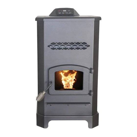
Owner's Instruction and Operation Manual
Model Number:
AP5501S
Report Number: F19-549
Certified to ASTM E1509-12 (2017)
and Certified to ULC-S627-00-REV1
Mobile Home Approved
* All Pictures In This Manual Are For Illustrative Purposes Only. Actual Product May Vary.
Save These Instructions In A Safe Place For Future Reference.
SAFETY NOTICE: If this heater is not properly installed, a house fire may result.
For your safety, follow the installation instructions. Never use make-shift
compromises during the installation of this heater. Contact local building or
fire officials about permits, restrictions and installation requirements in your
area. NEVER OPERATE THIS PRODUCT WHILE UNATTENDED.
CAUTION! Please read this entire manual before you install or use your new room
heater. Failure to follow instructions may result in property damage, bodily injury,
or even death. Improper Installation Will Void Your Warranty!
U.S. Environmental Protection Agency
Certified to comply with 2020 particulate
emissions standards.
THIS MANUAL IS SUBJECT TO CHANGE WITHOUT NOTICE.
© 2021 United States Stove Company, 227 Industrial Park Rd., South Pittsburg, TN 37380
R
CALIFORNIA PROPOSITION 65 WARNING:
This product can expose you to chemicals including carbon
monoxide, which is known to the State of California to cause
cancer, birth defects, and/or other reproductive harm. For
more information, go to
852715K-0204K
www.P65warnings.ca.gov
Ph. 800-750-2723
Advertisement
Table of Contents

Subscribe to Our Youtube Channel
Related Manuals for Ashley AP5501S


Summary of Contents for Ashley AP5501S
- Page 1 Owner’s Instruction and Operation Manual Model Number: AP5501S Report Number: F19-549 Certified to ASTM E1509-12 (2017) and Certified to ULC-S627-00-REV1 Mobile Home Approved * All Pictures In This Manual Are For Illustrative Purposes Only. Actual Product May Vary. 852715K-0204K Save These Instructions In A Safe Place For Future Reference.
- Page 2 Your stove is Certified to ASTM E1509-12 (2017)and Certified to ULC S627-00. This manual describes the installation and operation of the Ashley, AP5501S wood heater. This heater meets the 2020 U.S. Environmental Protection Agency’s crib wood emission limits for wood heaters sold after May 15, 2020.
-
Page 3: Installation Checklist
INSTALLATION CHECKLIST Your Wood Stove should be installed by a qualified installer only. An NFI qualified Installer can be found at www.nficertified.org/public/find-an-nfi-pro/ CUSTOMER SERVICE 1-800-750-2723 ext 5050 Text to 423-301-5624 Email to: Customerservice@usstove.com COMMISSIONING CHECKLIST This Checklist is to be completed in full by the qualified person who installs this unit. Keep this page for future reference. - Page 4 ASSEMBLY INSTRUCTIONS FOR CUSTOMER SERVICE CALL: 800-750-2723 EXT 5050 Pull the factory installed wires out of the top of 3. Connect the factory installed wiring harnesses the stove. There will be two wire harnesses, as to the control panel as shown. shown.
-
Page 5: Installation
INSTALLATION SAFETY NOTICE CAUTION: • IF THIS STOVE IS NOT PROPERLY INSTALLED, BURNING FUEL CREATES CARBON MONOXIDE A HOUSE FIRE MAY RESULT. TO REDUCE THE AND CAN BE HAZARDOUS TO YOUR HEALTH RISK OF FIRE, FOLLOW THE INSTALLATION IF NOT PROPERLY VENTED. INSTRUCTIONS. -
Page 6: Floor Protection
INSTALLATION FOR CUSTOMER SERVICE CALL: 800-750-2723 EXT 5050 IMPROPER INSTALLATION clearances and restrictions. Any reduction in clearance to combustibles may only be done by The use of other components other than stated means approved by a regulatory authority. herein could cause bodily harm, heater damage, and void your warranty. -
Page 7: Venting Requirements
INSTALLATION extend a minimum or 36” (914 mm) above the roof ATTENTION: line of the mobile home and must be installed DO NOT VENT UNDER ANY PORCH, DECK, using a certified ceiling fire stop and rain cap. AWNING, OR IN ANY SEMI ENCLOSED OR •... -
Page 8: Pellet Vent Termination
INSTALLATION vent must not exceed 4-feet. This could cause back area where the vent pipe penetrates to the exterior pressure. Use no more than 180 degrees of elbows of the home must be sealed with silicone or other (two 90-degree elbows, or two 45-degree and one means to maintain the vapor barrier between the 90-degree elbow, etc.) to maintain adequate draft. -
Page 9: Through The Wall Installation
INSTALLATION C. Minimum 3-foot (0.91m) clearance from any windows. We recommend Simpson Dura-Vent® or adjacent building. Metal-Fab® kits. D. Minimum 7-foot (2.13m) clearance from any grade when adjacent to public walkways. E. Minimum 2-foot (0.61m) clearance above any grass, plants, or other combustible materials. F. - Page 10 OPERATION INSTRUCTIONS NEVER OPERATE THIS PRODUCT WHILE UNATTENDED PANEL CONTROLS change on the bar graph starting from heat range “1” to heat range “5”. C. °C / °F Button • The °C / °F button changes the two digit display from degrees Celsius to degrees Fahrenheit.
-
Page 11: Proper Fuel
OPERATION INSTRUCTIONS to pass into the auger assembly. The fuel adjuster is 8. Railroad ties or pressure-treated wood; located inside the hopper. Note: The factory default 9. Manure or animal remains; setting for this is full open. To decrease the flow of 10. -
Page 12: Pre-Start-Up Check
OPERATION INSTRUCTIONS BUILDING A FIRE introduced by hand will not increase heat output but may seriously impair the stoves performance Never use a grate or other means of supporting by generating considerable smoke. Do not burn the fuel. Use only the burn pot supplied with this wet pellets. -
Page 13: Opening Door
OPERATION INSTRUCTIONS REFUELLING • The hopper and stove top will be hot during operation; therefore, you should always use some type of hand protection when refuelling your stove. • Never place your hand near the auger while the stove is in operation. We recommend that you not let the hopper drop below 1/4 full. -
Page 14: Optimal Operation
OPERATION INSTRUCTIONS Your stove is equipped with a high temperature the burn pot to remove any build up that may thermodisc. This unit has a manual reset prevent air from moving through the burn pot thermodisc. This safety switch has two functions. freely. -
Page 15: Maintenance
MAINTENANCE NEVER OPERATE THIS PRODUCT WHILE UNATTENDED bottom. The creosote should be removed with a CAUTION: brush specifically designed for the type of chimney • FAILURE TO CLEAN AND MAINTAIN THIS in use. A qualified chimney sweep can perform this UNIT AS INDICATED CAN RESULT IN POOR service. -
Page 16: Blower Motors
MAINTENANCE 3. Vacuum ashes from the firebox. BE SURE THAT cloth. If scratches appear, or you wish to renew your ASHES ARE COOL TO THE TOUCH BEFORE paint, contact your authorized dealer to obtain a VACUUMING. Some vacuum cleaners may leak can of suitable high-temperature paint. -
Page 17: Maintenance Schedule
MAINTENANCE stop flowing (this can be done by pressing the “ON” Monthly or Daily Weekly button with the viewing door open). Vacuum out as needed the hopper. Thoroughly clean the burn pot, and Burn Pot Stirred Empty firebox. It may be desirable to spray the inside of the cleaned hopper with an aerosol silicone spray Combustion Brushed... -
Page 18: Troubleshooting Guide
TROUBLESHOOTING GUIDE When your stove acts out of the ordinary, the first reaction is to call for help. This guide may save time and money by enabling you to solve simple problems yourself. Problems encountered are often the result of only five factors: 1) poor fuel;... - Page 19 TROUBLESHOOTING GUIDE Display is Flashing “E2” Possible Causes Possible Remedies: (Unplug stove first when possible) Unhook air hose from the air switch and blow through it. Airflow switch hose or stove attachment If air flows freely, the hose and tube are fine. If air will not pipes for hose are blocked.
- Page 20 TROUBLESHOOTING GUIDE Display is Flashing “E3” Possible Causes Possible Remedies: (Unplug stove first when possible) The hopper is out of pellets Refill the hopper. The air dampener is too far open for a low If on the low setting, you may need to close the dampener feed setting all the way.
- Page 21 TROUBLESHOOTING GUIDE Display is Flashing “E4” Possible Causes Possible Remedies: (Unplug stove first when possible) The air inlet, burnpot, interior combustion chambers, combustion blower, Follow all cleaning procedures in the maintenance section exhaust pipe are blocked with ash or foreign of the owner’s manual.
- Page 22 TROUBLESHOOTING GUIDE Stove Feeds Pellets, But Will Not Ignite Possible Causes Possible Remedies: (Unplug stove first when possible) In some situations it may be necessary to have the damper completely closed for ignition to take place. After there is Air damper open too far for ignition. a flame, the damper can then be adjusted for the desired feed setting.
- Page 23 TROUBLESHOOTING GUIDE Convection Blower Shuts Off And Comes Back On Possible Causes Possible Remedies: (Unplug stove first when possible) The convection blower is overheating and Clean any dust off of the windings and fan blades. If tripping the internal temperature shutoff. cleaning the blower does not help, the blower may be bad.
- Page 24 TROUBLESHOOTING GUIDE High Limit Switch Keeps Tripping Possible Causes Possible Remedies: (Unplug stove first when possible) The convection blower is overheating and Clean any dust off of the windings and fan blades. If oiling tripping the internal temperature shutoff. the blower does not help, the blower may be bad. If operating the heater on the highest heat setting, the The stove is being left on the highest setting room temperature could increase enough and lead to...
-
Page 25: Repair Parts
REPAIR PARTS © 2021 United States Stove Company... - Page 26 To order parts: Call 1-800-750-2723 Ext 5051 or Email to: parts@usstove.com IN ORDER TO MAINTAIN WARRANTY, COMPONENTS MUST BE REPLACED USING ASHLEY PARTS PURCHASED THROUGH YOUR DEALER OR DIRECTLY FROM ASHLEY. USE OF THIRD PARTY COMPONENTS WILL VOID THE WARRANTY.
-
Page 27: Wiring Diagram
WIRING DIAGRAM 7.5A 250V FUSE 1.25A 250V FUSE Ensure the wires are connected to the bottom two prongs of the hopper switch as shown. CORRECT WRONG © 2021 United States Stove Company... -
Page 28: Service Record
SERVICE RECORD It is recommended that your heating system is serviced regularly and that the appropriate Service Interval Record is completed. SERVICE PROVIDER Before completing the appropriate Service Record below, please ensure you have carried out the service as described in the manufacturer’s instructions. Always use the manufacturer's specified spare part when replacement is necessary.
Need help?
Do you have a question about the AP5501S and is the answer not in the manual?
Questions and answers