Table of Contents
Advertisement
•
WARNING: If your appliance is not properly installed a house fire may result. For your safety,
follow the installation directions. Contact local building or fire officials about restrictions and
Installation inspection requirements in your area.
•
Please Read This entire manual before installation and use of this pellet fuel-burning room heater.
Failure to follow these instructions could result in property damage, bodily injury, or even death.
•
Save these instructions.
The French version is available for download from the site U.S. Stove: http://www.usstove.com/ La version
française est disponible pour téléchargement à partir du site U.S. Stove: http://www.usstove.com/
PROFESSIONAL INSTALLATION IS HIGHLY RECOMMENDED
OWNER'S MANUAL
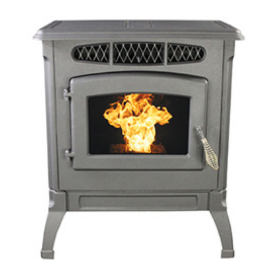
Classic Cast APC4000
U.S. Environmental Protection Agency
Certified to comply with 2015 particulate emissions standards.
227 Industrial Park Road
P.O. Box 151 South
U. S. Stove
Pittsburg, TN 37380
(800) 750-2723
852400B-4301F
Advertisement
Table of Contents

Related Manuals for Ashley Classic Cast APC4000


Summary of Contents for Ashley Classic Cast APC4000
- Page 1 OWNER’S MANUAL Classic Cast APC4000 U.S. Environmental Protection Agency Certified to comply with 2015 particulate emissions standards. • WARNING: If your appliance is not properly installed a house fire may result. For your safety, follow the installation directions. Contact local building or fire officials about restrictions and installation inspection requirements in your area.
- Page 2 INTRODUCTION This manual describes the installation and operation of the Ashley, APC4000 wood heater. This heater meets the 2015 U.S. Environmental Protection Agency's crib wood emission limits for wood heaters sold after May 15, 2015. Under specific test conditions this heater has been shown to deliver heat at rates ranging from 6,569 to 34,785 Btu/hr.
-
Page 3: Safety Precautions
SAFETY PRECAUTIONS • Do not operate your stove if you smell smoke can shine on the unit, it is possible this can cause coming from it. Turn it off, monitor it, and call your the temperature of the stove to rise to operational dealer. - Page 4 INSTALLATION SPECIFICATIONS Width: 25 ¼” Height: 29 ½” Depth: 24 ¼” Weight: 340 lbs. Flue size: 3” or 4” Hopper Capacity: Up to 40 lbs. (this can vary widely depending on pellet size, length, and diameter) EPA status: exempt Burn time: 1 lb. to 4 ½ lbs. per hour FIGURE 1 BTU range: 8,200 to 40,000 Approved...
- Page 5 INSTALLATION COMBUSTION AIR SUPPLY For a mobile home installation the stove must be connected to an outside source of combustion air. A 2” inside diameter metallic pipe, either flexible or rigid, may be attached to the inlet at the stove’s rear (refer to figure 4).
- Page 6 INSTALLATION Equivalent Vent Length (EVL) The longer the run of pipe in your installation (both with inserts and freestandings), the more restriction there is in the system. Therefore, larger diameter pipe should be used. • Use 4” pipe if you have more than 15 feet of equivalent vent length. •...
- Page 7 INSTALLATION B. VERTICALLY WITH NEW CHIMNEY SYSTEM (Refer to Figure 7) NOTE: See “VENTING” and follow L-Vent chimney manufacturer’s instructions. OPTION: To achieve a center vertical installation a 45º elbow and a clean-out tee can be used to offset the pipe from the exhaust outlet to the rear center of the stove.
- Page 8 INSTALLATION D. VERTICALLY INTO EXISTING MASONRY FIREPLACE NOTE: See “VENTING” and follow L-Vent chimney manufacturer’s instructions. 1. Have the masonry chimney inspected by a qualified chimney sweep or installer to determine its structural condition. 2. You will need a pipe length equal to the chimney height from the hearth.
- Page 9 INSTALLATION ELECTRICAL INSTALLATION This stove is provided with a 6-foot grounded electrical cord extending from the rear of the stove. We recommend connecting to a good quality surge protector that is plugged into a standard three-prong, 120V, 60 Hz electrical outlet. Do NOT connect the unit to a GFCI socket.
- Page 10 OPERATION PANEL CONTROLS (SEE FIGURE 12) The blowers and automatic fuel supply are controlled from a panel on the left- hand side of the furnace. The control panel functions are as follows. a. ON/OFF SWITCH • When pushed the stove will automatically ignite. No other firestarter is necessary.
- Page 11 OPERATION PROPER FUEL This heater is designed to burn only PFI Premium grade pellets. This appliance can also burn pellets rated as standard after May 16, 2015 DO NOT BURN: 1. Garbage; 10. Salt water driftwood or other previously salt water 2.
- Page 12 OPERATION THE HOTROD AUTOMATIC FIRESTARTER a. Fill hopper and clean burnpot. b. Press “Power” button. Make sure light is on. c. The damper should be completely closed or open no more than ¼” during start-up. This will vary depending on your installation and elevation. Once fire is established adjust for desired flame increasing the amount the damper is open as the heat setting is increased.
- Page 13 OPERATION RE-STARTING A WARM STOVE If the stove has been shut off, and you want to re-start it while it is still warm, the “on/off” button must be held down for 2 seconds. IF STOVE RUNS OUT OF PELLETS The fire goes out and the auger motor and blowers will run until the stove cools. This will take 30 to 45 minutes. After the stove components stop running the “Power”...
- Page 14 OPERATION PLEASE READ THIS! OPERATING SAFETY PRECAUTIONS a. Hot while in operation. Keep children, clothing, and furniture away. Contact may cause skin burns. b. If you notice a smoldering fire (burnpot full but no visible flame) AND a heavy smoke buildup in firebox, im mediately TURN OFF the stove, but DO NOT unplug it.
-
Page 15: Thermostat Installation
THERMOSTAT INSTALLATION OPTIONAL THERMOSTAT A thermostat may help you maintain a constant house temperature automatically. A millivolt thermostat is required. On/Off High/Low A fixed wall mount or a hand held model can be used. The control panel can be set up two ways to operate your stove Manual in thermostat mode. - Page 16 MAINTENANCE FAILURE TO CLEAN AND MAINTAIN THIS UNIT AS INDICATED CAN RESULT IN POOR PERFORMANCE AND SAFETY HAZARDS. NEVER CLEAN WHEN HOT. NOTE: Inspect burn pot periodically to see that holes have not become plugged, if so, clean thoroughly. ASH REMOVAL Ashes should be placed in a metal container with a tight-fitting lid.
- Page 17 MAINTENANCE CLEANING a. Heat Exchange Tubes – Your stove is designed with a built-in heat exchange tube cleaner. This should be used every two or three days to remove accumulated ash on the tubes, which reduces heat transfer on this furnace. Baffle Plates Insert the handle end (with hole) of the cleaning tool onto the cleaning rod (refer to figure 15).
- Page 18 MAINTENANCE CHIMNEY CLEANING a. Creosote Formation – When any wood is burned slowly, it produces tar and other organic vapors, which combine with expelled moisture to form creosote. The creosote vapors condense in the relatively cool chimney flue or a newly started fire or from a slow-burning fire. As a result, creosote residue accumulates on the flue lining.
-
Page 19: Troubleshooting Guide
TROUBLESHOOTING GUIDE When your stove acts out of the ordinary, the first reaction is to call for help. This guide may save time and money by enabling you to solve simple problems yourself. Problems encountered are often the result of only five factors: 1) poor fuel;... - Page 20 TROUBLESHOOTING GUIDE STOVE SHUTS OFF AND THE #3 LIGHT FLASHES Possible Causes: Possible Remedies: (Unplug stove first when possible) The hopper is out of pellets. Refill the hopper. If burning on the low setting, you may need to close the The air damper is too far open for a low feed setting.
- Page 21 TROUBLESHOOTING GUIDE STOVE FEEDS PELLETS, BUT WILL NOT IGNITE Possible Causes: Possible Remedies: Push the air damper in closer to the side of the stove for startup. In some situations it may be necessary to have the Air damper open too far for ignition. damper completely closed for ignition to take place.
- Page 22 TROUBLESHOOTING GUIDE STOVE WILL NOT FEED PELLETS, BUT FUEL FEED LIGHT COMES ON AS DESIGNED Possible Causes: Possible Remedies: Fuse on control board blew Remove the control board. If the fuse appears to be bad, replace it with a 5 Amp 125 Volt fuse. Plug the stove back in and try to run the unit.
- Page 23 TROUBLESHOOTING GUIDE • GLASS “SOOT’S” UP AT A VERY FAST RATE • FLAME IS LAZY, DARK, AND HAS BLACK TIPS • AFTER STOVE HAS BEEN ON FOR A WHILE, THE BURNPOT OVERFILLS Possible Causes: Possible Remedies: Stove or vent pipe is dirty, which Follow all cleaning procedure in the maintenance section of the restricts airflow through the burnpot. owner’s manual. Vent pipe installed improperly. Check to make sure the vent pipe has been installed according to the criteria in the owner’s manual.
- Page 24 ELECTRICAL DIAGRAM -24-...
-
Page 25: Replacement Parts
REPLACEMENT PARTS ITEM PART# Pressure Switch 80621 Hose, Silicone 891121 Auger Motor 80642 Maintenance Tool A-TOOL Burnpot A-S-BURNPOT Circuit Board / Control Panel A-E-101 Combustion Blower A-E-027J Convection Blower A-E-033A Rope Gasket 88066 Door Glass C-D-031 Ignitor Cartridge 80607 Thermodisc 60T21 Low Limit 80610 Thermodisc, High Temp C-E-090-21... - Page 26 Service Record It is recommended that your heating system is serviced regularly and that the appropriate Service Interval Record is completed. Service Provider: Before completing the appropriate Service Record below, please ensure you have carried out the service as described in the manufacturer’s instructions.
- Page 27 Limited Warranty Model APC4000 The operation of this unit in a manner inconsistent with the owner’s manual will void the warranty and is also against federal regulations. United States Stove Company warrants to the original purchaser its products against premature failure of any component due to workmanship, quality, or materials as follows: TIME PERIOD Firebox / Heat Exchanger ..........................
- Page 28 NOTES -28-...
- Page 29 HOW TO ORDER REPLACEMENT PARTS / COMMANDE DE PIÈCES DE RECHANGE This manual will help you obtain efficient, dependable service from your stove, and enable you to order repair parts correctly. Keep this manual in a safe place for future reference. When writing, always give the full model number which is on the nameplate attached to the stove.
Need help?
Do you have a question about the Classic Cast APC4000 and is the answer not in the manual?
Questions and answers