
Related Manuals for KPS KPS-PA60


Summary of Contents for KPS KPS-PA60
- Page 1 MANUAL DE FUNCIONAMIENTO INSTRUCTIONS MANUAL Pinza amperimétrica digital Digital clamp meter KPS-PA60 602150002...
-
Page 2: Información Sobre Seguridad
KPS-PA60 • Pinza amperimétrica digital INFORMACIÓN SOBRE SEGURIDAD ADVERTENCIA TENGA MUCHO CUIDADO AL UTILIZAR ESTE INSTRUMENTO. El uso inadecuado de este dispositivo puede provocar descargas eléctricas o daños en el mismo. Tome todas las medidas de seguridad habituales y siga las precauciones indicadas en este manual. - Page 3 KPS-PA60 • Pinza amperimétrica digital indicados en las especificaciones. • No toque las puntas metálicas de las puntas de prueba cuando el instru- mento esté conectado al circuito a medir. • Mantenga los dedos por detrás de los protectores de la sonda al realizar mediciones con una tensión eficaz de más de 60V CC o 30V rms CA.
- Page 4 KPS-PA60 • Pinza amperimétrica digital Categoría de sobretensión (instalación) III, grado de contami- CAT III nación 2 según IEC1010-1. Hace referencia al nivel de protección contra la tensión de rigidez dieléctrica a impulso suministrada. Cumple con la directiva de la Unión Europea Terminal de tierra 1.4 Mantenimiento...
- Page 5 KPS-PA60 • Pinza amperimétrica digital nuidad y de diodos. • Ajuste automático de la escala. • El instrumento cuenta con una función de retención de la lectura. • El instrumento está equipado con una función de puesta a cero automática (en la escala A CC). • El instrumento puede medir la frecuencia por medio de la pinza. Cuenta con una función de apagado automático.
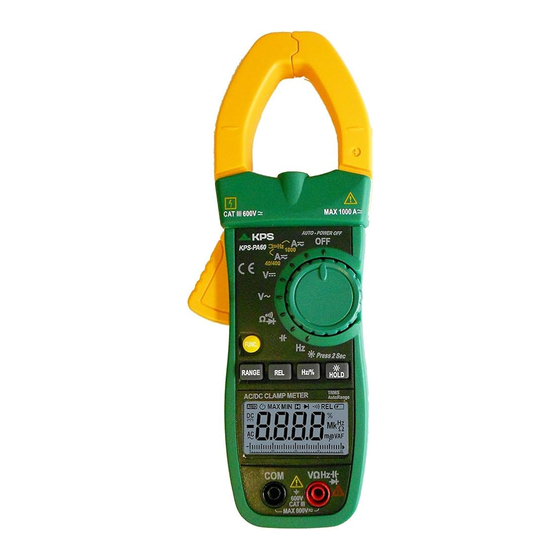
- Page 6 KPS-PA60 • Pinza amperimétrica digital 2.2 Selector, botones y conectores de entrada Botón HOLD/B.L • Para retener la lectura o controlar la retroiluminación. Botón FUNC • Para cambiar entre las diferentes funciones de medición. Botón REL...
- Page 7 KPS-PA60 • Pinza amperimétrica digital • Tecla para la medición del valor relativo. Botón Hz/% • Para cambiar entre las funciones de medición de frecuencia y trabajo. Botón RANGE • Para cambiar entre la escala manual y automática. Selector giratorio • Para seleccionar las distintas funciones y escalas.
-
Page 8: Especificaciones
KPS-PA60 • Pinza amperimétrica digital Valor máximo medido Valor mínimo medido Medición de A CC cero y relativa Apagado automático Batería baja Indica que los datos de la pantalla están siendo reteni- dos. Porcentaje (ciclo de trabajo) ,VmV Milivoltios, Voltios (tensión) Amperios (corriente) ,mF,μFnF Nanofaradios, Microfaradios kΩ,MΩ,Ω Ohmios, Kiloohmios, Megaohmios (resistencia) - Page 9 KPS-PA60 • Pinza amperimétrica digital • Tiempo de apagado automático: 15 minutos • Alimentación: 3 pilas de 1,5V AAA • Indicación de batería baja ‘ ’ en la pantalla • Factor de temperatura: < 0,1×precisión / ºC • Temperatura de funcionamiento: 0°C a 40°C (32°F a 104°F) • Temperatura de almacenamiento: -10°C a 50°C (10°F a 122°F) • Dimensiones: 225×86×33mm • Peso aproximado 320g (pilas incluidas) 3.2 Especificaciones técnicas...
- Page 10 KPS-PA60 • Pinza amperimétrica digital 3.2.3 Tensión CC Escala de medición Resolución Precisión 400mV 0,1mV ± (1,0% de la lectura + 2 dígitos) 0,001V 0,01V ± (0,7% de la lectura + 2 dígitos) 400V 0,1V 600V ± (0,8% de la lectura + 2 dígitos) - Impedancia de entrada: 10MΩ...
- Page 11 KPS-PA60 • Pinza amperimétrica digital 3.2.5 Frecuencia Escala de medición Resolución Precisión 10Hz 0,01Hz 1kHz 0,001Hz ±(1,5% de la lectura + 5 dígitos) >1kHz 0,001Hz - Escala de medición: 40 ~ 1kHz - Escala de corriente de entrada: ≥70A CA rms (mayor corriente de entrada con una mayor frecuencia) - Corriente máxima de entrada: 1000A CA rms) 3.2.5.2 Escala V CA:...
- Page 12 KPS-PA60 • Pinza amperimétrica digital 3.2.5.3 Escala Hz/TRABAJO: Escala de medición Resolución Precisión 9,999Hz 0,001Hz 99,99Hz 0,01Hz 999,9Hz 0,1Hz 9,999kHz 0,001kHz ±(0,5% de la lectura + 5 dígitos) 99,99kHz 0,01kHz 999,9kHz 0,1kHz 9,999MHz 0,001MHz - Protección contra sobrecarga: 250V CC o 250V CA rms.
- Page 13 KPS-PA60 • Pinza amperimétrica digital 3.2.7 Resistencia Escala de medición Resolución Precisión 400Ω 0,1Ω 4kΩ 0,001kΩ ±(0,8% de la lectura + 3 dígitos) 40kΩ 0,01kΩ 400kΩ 0,1kΩ 4MΩ 0,001MΩ ±(1,2% de la lectura + 3 dígitos) 40MΩ 0,1MΩ - Tensión de circuito abierto: 0,4V - Protección contra sobrecarga: 250V CC o CA (RMS)
-
Page 14: Instrucciones De Funcionamiento
KPS-PA60 • Pinza amperimétrica digital 3.2.11 Capacitancia Escala de medición Resolución Precisión 40nF 0,01nF 400nF 0,1nF 4μF 0,001nF ±(4,0% de la lectura + 5 dígitos) 40μF 0,01μF 400μF 0,1μF 4000μF 1μF - Protección contra sobrecarga: 250V CC o CA (RMS) INSTRUCCIONES DE FUNCIONAMIENTO 4.1 Retención de las lecturas... - Page 15 KPS-PA60 • Pinza amperimétrica digital el valor de referencia. 5) Pulse la tecla FUNC o utilice el selector de modo para cancelar el modo de medición RELΔ y regresar al modo normal (el símbolo RELΔ desaparecerá de la pantalla). 6) Activación de OL: en el modo RELΔ, se muestra el símbolo OL cuando el valor de entrada es mayor que el valor permitido en el modo de medición. Pulse de nuevo la tecla para cancelar la función de medición relativa. Desac- tívelo para acceder al modo RELΔ cuando se muestre el mensaje OL.
- Page 16 KPS-PA60 • Pinza amperimétrica digital 2) Pulse la tecla y encienda el instrumento, la función de apagado automático quedará cancelada, el símbolo “ ” desaparecerá de la pantalla y el instru- mento pasará modo de inactividad (apagado). Pulse la tecla y encienda el instrumento para volver a activar de la función de apagado automático.
- Page 17 KPS-PA60 • Pinza amperimétrica digital 4.8 Preparativos para la medición • Encienda el instrumento girando el selector giratorio. Si la tensión es menor de 3,7V, aparecerá el símbolo “ ” y será necesario cambiar las pilas. • El símbolo “...
- Page 18 KPS-PA60 • Pinza amperimétrica digital 5) “ ” significa que la corriente máxima de entrada es de 1000A CA rms. 4.10 Medición de corriente CC • Coloque el selector giratorio en la posición de la escala A . • Pulse la tecla FUNC para pasar al modo de medición de corriente CC. • Pulse el botón “REL” para poner a cero el instrumento. • Pulse el gatillo para abrir las mordazas. Rodee por completo un único con- ductor.
- Page 19 KPS-PA60 • Pinza amperimétrica digital carga para efectuar la medición. • Observe la medición en la pantalla. NOTA: 1) “ ”significa que la tensión máxima de entrada es de 600V CC. 2) Si el resultado de la prueba es superior a 600V CC, la pantalla mostrará el símbolo “OL” y el avisador integrado emitirá un sonido.
- Page 20 KPS-PA60 • Pinza amperimétrica digital • Pulse la tecla “Hz/%” para cambiar a la medición de frecuencia. • Observe la medición en la pantalla. NOTA: 1) No coloque más de un cable dentro de las mordazas durante la prueba, o de lo contrario el valor obtenido podría ser incorrecto. 2) La escala de comprobación de la frecuencia es de 10Hz - 1kHz. Si la fre- cuencia es menor de 10,0 Hz, la pantalla mostrará...
- Page 21 KPS-PA60 • Pinza amperimétrica digital para efectuar la medición. • Observe la medición en la pantalla. 4.14 Medición del trabajo 4.14.1 Mediante la escala A (desde la pinza de corriente): • Coloque el selector giratorio en la posición A . • Presione el gatillo para abrir las mordazas. Rodee por completo un único conductor.
- Page 22 KPS-PA60 • Pinza amperimétrica digital 4.14.3 Mediante la escala HZ/TRABAJO: • Introduzca el cable de prueba negro en el conector COM y el cable • de prueba rojo en el conector de ENTRADA. • Coloque el selector giratorio en la posición HZ/TRABAJO. • Pulse la tecla “Hz/%” para cambiar a la medición de TRABAJO.
- Page 23 KPS-PA60 • Pinza amperimétrica digital • Pulse el botón “SEL” para cambiar a la prueba • Conecte el cable de prueba rojo al ánodo y el cable de prueba negro al cátodo del diodo para efectuar la prueba. • Observe la medición en la pantalla.
-
Page 24: Mantenimiento
KPS-PA60 • Pinza amperimétrica digital • Una vez que el condensador esté completamente descargado, conecte las puntas de prueba a los dos extremos del condensador para efectuar la me- dición. • Observe la medición en la pantalla. NOTA: Cuando se realizan mediciones de altas capacidades, las lecturas pueden tardar algún tiempo en estabilizarse (aproximadamente 30 segundos para la escala entre 400μF y 4000μF). -
Page 25: Safety Information
KPS-PA60 • Digital clamp meter SAFETY INFORMATION WARNING BE EXTREMELY CAREFUL WHEN USING THIS METER. Improper use of this device can result in electric shock or destruction of the meter. Take all normal safety precautions and follow the safeguards suggest- ed in this manual. - Page 26 KPS-PA60 • Digital clamp meter with an effective voltage above 60V DC or 30V rms AC. • Do not take voltage measurement if the value between the terminals and earth ground exceeds 600V. • Select the highest range if the value scale to be measured in the manual range is unknown.
- Page 27 KPS-PA60 • Digital clamp meter 1.4 Maintenance • Do not attempt to remove the rear case to adjust or repair the meter. • Such actions should only be performed by a technician who fully under- stands the meter and the danger involved.
- Page 28 KPS-PA60 • Digital clamp meter (5) Function Switch Button (FUNC) (6) Manual range (RANGE) (7) Relative Switch Button (REL) (8) Liquid Crystal Display (LCD) (9) COM Jack (10) Input Jack (11) Hz/Duty Switch Button (Hz/%) (12) Reading Hold/Back Light Button (HOLD/B.L) (13) Rotary selector (14) OFF - power switch (15) “+” Symbol...
-
Page 29: Switch, Buttons And Input Jacks
KPS-PA60 • Digital clamp meter 2.2 SWITCH, BUTTONS AND INPUT JACKS HOLD/B.L Button • For holding the reading or control backlight FUNC Button • For switching among measuring functions REL Button • The key is the relative value measurement. Hz/% Button • For switching between frequency and duty measuring functions. RANGE Button • For switching auto range and manual range. Rotary Selector • For selecting functions and ranges. -
Page 30: Specifications
KPS-PA60 • Digital clamp meter Alternating current Direct current Diode test Continuity buzzer AUTO Auto range mode The maximum value is being measured The minimum value is being measured DCA zero and relative measure Auto power off Battery low This indicates that the display data is being held. - Page 31 KPS-PA60 • Digital clamp meter • Operating altitude: max. 2000 meters (7000 ft.) • Display: 4000 counts with analog bar LCD display • Maximum value display: 4000 digits • Polarity indication: automatic; „-„ for negative polarity. • Overrange indication: „0L‟ or „-0L‟ • Converter Rate: 3 times/sec; Bar graph: 30 times/sec.
- Page 32 KPS-PA60 • Digital clamp meter Max. input current: 1000A CC 3.2.3 DC Voltage Range Resolution Accuracy 400mV 0,1mV ± (1,0% of reading + 2 digits) 0,001V 0,01V ± (0,7% of reading + 2 digits) 400V 0,1V 600V ± (0,8% of reading + 2 digits) - Input impedance: 10MΩ...
- Page 33 KPS-PA60 • Digital clamp meter 3.2.5 Frequency Range Resolution Accuracy 10Hz 0,01Hz 1kHz 0,001Hz ±(1,5% of reading + 5 digits) >1kHz 0,001Hz - Measurement range: 10 ~ 1kHz - Input current range: ≥70A rms AC (higher input current at higher frequency) - Max. Input current: 1000A rms AC 3.2.5.2 By ACV range:...
- Page 34 KPS-PA60 • Digital clamp meter 3.2.5.3 By Hz/DUTY range: Range Resolution Accuracy 9,999Hz 0,001Hz 99,99Hz 0,01Hz 999,9Hz 0,1Hz 9,999kHz 0,001kHz ±(0,5% of reading + 5 digits) 99,99kHz 0,01kHz 999,9kHz 0,1kHz 9,999MHz 0,001MHz - Overload protection: 250V dc or 250V ac rms.
- Page 35 KPS-PA60 • Digital clamp meter 3.2.7 Resistance Range Resolution Accuracy 400Ω 0,1Ω 4kΩ 0,001kΩ ±(0,8% of reading + 3 digits) 40kΩ 0,01kΩ 400kΩ 0,1kΩ 4MΩ 0,001MΩ ±(1,2% of reading + 3 digits) 40MΩ 0,1MΩ - Open circuit voltage: 0.4V - Overload protection: 250V DC or rms AC 3.2.8 Diode...
- Page 36 KPS-PA60 • Digital clamp meter 3.2.11 Capacitance Range Resolution Accuracy 40nF 0,01nF 400nF 0,1nF 4μF 0,001nF ±(4,0% of reading + 5 digits) 40μF 0,01μF 400μF 0,1μF 4000μF 1μF - Overload protection: 250V DC or rms AC OPERATION INSTRUCTION 4.1 Holding readings • Press the “HOLD/B.L”...
- Page 37 KPS-PA60 • Digital clamp meter 6) OL triggering: Under RELΔ mode, OL shows when input value larger than the allowed value of the measurement mode. Press the key again, the relative measurement function will be cancelled. Disable to enter RELΔ mode when OL shows. 7) No analog section bar function under RELΔ mode. 4.3 Switching frequency or duty • During working at the voltage or current ranges, press the “Hz/%” button one time, frequency of the voltage or current will be measured. Press the “Hz/%”...
- Page 38 KPS-PA60 • Digital clamp meter 4.6 Back light and clamp lighting bulb • Press the ”HOLD/B.L” button for two or more seconds to switch on the back light if the light in the environment is too dim for taking reading, which will last for 15 seconds.
- Page 39 KPS-PA60 • Digital clamp meter • Connect the common test lead first and then the charged test leads when making connection. Take away the charged test lead first when disconnecting.a. 4.9 Measuring AC Current WARNING Beware of Electrocution.Ensure that the test leads are disconnected from the meter before making current clamp measurements.
- Page 40 KPS-PA60 • Digital clamp meter test value might be obtained. 2) For optimum results, press the “REL” button to make the meter get into zero first. 3) For optimum results, center the conductor in the jaw. 4) At the manual range mode, when only „OL‟ or „-OL‟ is shown¡ on the LCD, it means the measurement has exceeded the range. A higher range should be selected. 5) Under the manual range mode, when the scale of the value to be measured is unknown beforehand, set the range to the highest.
- Page 41 KPS-PA60 • Digital clamp meter INPUT jack. • Set the rotary selector to at the V range position. • Connect the test leads to the voltage source or load terminals for measu- rement. • Take the reading on the LCD.The polarity symbol denotes the polarity of the end connected by the red test lead.
- Page 42 KPS-PA60 • Digital clamp meter NOTE: 1) Frequency test range is 10Hz -10kHz. It is possible to test the frequency which is higher than 10kHz but the tolerance of the test result can not be en- sure. 2) “ ”means the maximum input voltage is 600V rms AC.
- Page 43 KPS-PA60 • Digital clamp meter INPUT jack. • Set the rotary selector to the V range. • Press the “Hz/%” to switch to DUTY measurement. • Connect test leads to the two end of the source or load for measurement. • Take the reading on the LCD..
- Page 44 KPS-PA60 • Digital clamp meter NOTE: 1) When the input is open, „OL‟ will appear on the LCD to indicate that the range has been exceeded. 2) For measuring resistance above 1MΩ, it may take a few seconds to get a steady reading. This is normal for high resistance reading. 4.16 Testing diode • Plug the black test lead into the COM jack and the red test lead into the INPUT jack.
-
Page 45: Maintenance
KPS-PA60 • Digital clamp meter NOTE: If the test leads are open or the resistance of the circuit is over 400Ω, “OL” will appear on the LCD. “OL”. 4.18 Measuring capacitance WARNING Beware of Electrocution. To avoid electric shock, make sure that the capacitors have been fully discharged before measuring the capaci- tance of a capacitor.. - Page 46 KPS-PA60 • Digital clamp meter 5.2 Replacing test leads WARNING The replacement must be test leads in good working condition with the same or equivalent rating: 1000V 10A. A test lead must be replaced if the insulation layer has been damaged, e.g. the wire inside is exposed.
- Page 47 KPS-PA60 • Digital clamp meter...
- Page 48 Pol. Industrial de Asipo Calle B, Parcela 41, nave 3 C.P.: E-33428 Llanera Asturias, España (Spain) Tel.: +34 985 081 870 Fax: +34 985 081 875 info@kps-soluciones.es www.kps-soluciones.es...
Need help?
Do you have a question about the KPS-PA60 and is the answer not in the manual?
Questions and answers