Table of Contents
Advertisement
Quick Links
Advertisement
Table of Contents

Subscribe to Our Youtube Channel
Related Manuals for Bacharach MVR-SC


Summary of Contents for Bacharach MVR-SC
- Page 2 Bacharach, Inc. warrants to buyer that it will convey good title to this product. Bacharach’s liability and buyer’s remedy under this warranty of title are limited to the removal of any title defects or, at the election of Bacharach, to the replacement of this product or parts thereof that are defective in title.
-
Page 3: Table Of Contents
MVR-SC™ Refrigerant Leak Monitor Table of Contents SECTION 1. INTRODUCTION About this Manual ....................................4 Iconography ......................................4 General Safety Statements ................................. 4 SECTION 2. PRODUCT DESCRIPTION Product Overview ....................................5 Design Features ....................................5 Bill of Materials ....................................5 Specifications ..................................... -
Page 4: Section 1. Introduction
1.1 About this Manual Thank you for investing in a Bacharach MVR-SC Refrigerant Leak Monitor. To ensure operator safety and the proper use of the controller, please read the contents of this manual for important information on the operation and maintenance of the instrument. -
Page 5: Section 2. Product Description
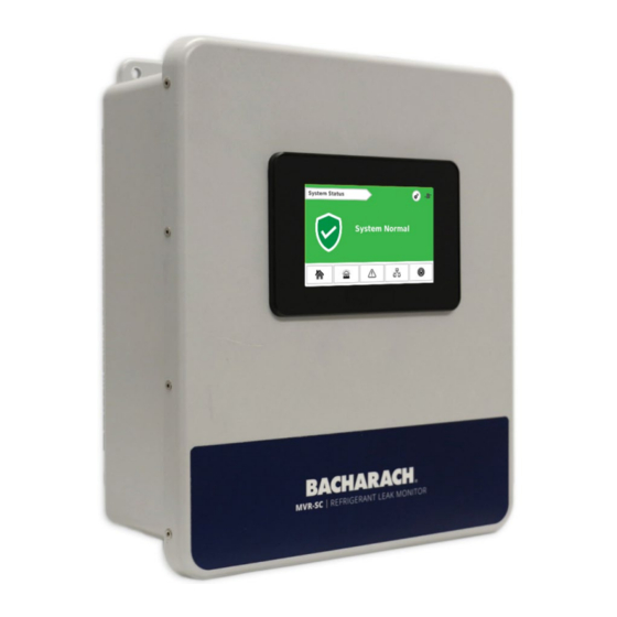
The MVR-300’s core functions include monitoring a network of connected MVR-300 refrigerant leak detectors for high or low PPM alarm events, hardware faults, and network connectivity. When an alarm is present, the MVR-SC activates the alarm relay, the Home Screen switches to red, and an audible buzzer is activated. Faults activate the fault relay, the Home Screen switches to amber, and an audible buzzer is activated. -
Page 6: Specifications
Relay Outputs 100 MVR-300 VRF refrigerant leak detectors 15 MVR-300 VRF refrigerant leak detectors / Gateway Device Capacity 7 Gateways / MVR-SC refrigerant leak monitor 1 × RS485 Modbus RTU Master (for direct addressing) Serial Port microSD Card and USB 2.0, up to 32GB;... -
Page 7: Components
MVR-SC™ Refrigerant Leak Monitor 2.5 Components Component Description PLC / Touch Screen USB Port Ethernet Port (Requires Shielded Cat 6 Cable) Fault Relay (250 VAC / 30 VDC, 2.0 AMP) Alarm Relay (250 VAC / 30 VDC, 2.0 AMP) Modbus Terminal Block (Requires Belden 3106 or Equivalent. -
Page 8: Network Components
Ethernet Network Switch (1100-2172, MOXA EDS-208A) An Ethernet network switch is used to provide connectivity between the MVR-SC Controller and the individual Modbus Gateways (up to 8 ports). Visit MOXA website (www.moxa.com) for more details. Modbus Gateway (1100-2198, MOXA MGate MB3170) -
Page 9: Section 3. Network Overview
Daisy Chained Gateway Network A small network of up to 15 MVR-300 detectors can be directly wired to the MVR-SC via the available Modbus Terminal Block in the controller’s enclosure. Combination of direct wired and gateway wired MVR-300 detectors can be deployed in a network. -
Page 10: Section 4. Installation
Be careful not to touch or disturb any of these components. CAUTION: RS-485 cable must be insulated to the highest voltage level in the system. IMPORTANT: Place the MVR-SC in an indoor setting free from the risk of exposure to water, high humidity or any hazardous conditions. -
Page 11: Mounting Instructions
MVR-SC™ Refrigerant Leak Monitor 4.4 Mounting Instructions The MVR-SC is equipped with an integral mounting flange. Four fasteners will be required. The mounting holes are Ø 0.3125” each. When mounting, take into account the degree of accessibility required for maintenance purposes when selecting a location. -
Page 12: Electrical And Communications Wiring
WARNING: Ensure wiring for relays and leak detectors are made before applying power. WARNING: Failure to ground electrical and communications wiring may result in communication errors. MVR-SC power source and Modbus Gateway power source should be two separate sources to prevent communication issues due to grounding. -
Page 13: Relay Wiring
IMPORTANT: Take care to ensure proper wiring for intended function: normally open and / or normally closed. The MVR-SC is equipped with (2) dry contact relays: (1) for faults and (1) for alarms. 1. Locate the fault relay terminals (#4, Section 2.4) and alarm relay terminals (#5, Section 2.4) -
Page 14: Connecting Ethernet Network Switches (1100-2172, Moxa Eds-208A)
MVR-SC™ Refrigerant Leak Monitor Communications Wiring Secure the Ethernet cable from the MVR-SC, a Modbus Gateway, or an Ethernet Switch to one of the available Ethernet ports on the gateway The MVR-300 gas detector utilizes RS485 communications to communicate with the MVR-SC. -
Page 15: Connecting Mvr-300'S
IMPORTANT: When inserting wire into the power and serial terminals, release the spring clamp by pushing the release latch back IMPORTANT: For additional MVR-300 installation instructions, please visit the Bacharach website (https://bit.ly/2L3bfJc) Connect the first MVR-300 detector’s Modbus port (3-wire) to the gateway. Subsequent MVR-300’s are daisy chained together to the first MVR-300. -
Page 16: Section 5. Commissioning
SECTION 5. COMMISSIONING 5.1 System Overview The MVR-SC has (6) primary screens: System Status (Home), Devices in Alarm, Devices in Fault, Communication (Comm.) Error, Floor List, and System Settings. Most status screens can be easily navigated to by using the Navigation Icons located on the bottom of most screens. - Page 17 Fault screen for a full list of faults). Comm. Error Status: Displays Minutes since data was last sent/received by the MVR-SC and the MVR-300 detector with an error. Floor List The Floor List screen displays the Total Device count of the network, each floor number on the network, and a status icon as a quick user reference to any alarms, faults, or errors on a floor’s detectors.
- Page 18 Floor List and Room List screens. Successful will appear under the Upload CSV button, if the floorplan is successfully uploaded to the MVR-SC. The CSV file must be located in the root folder of the USB in order to perform an upload.
-
Page 19: Commissioning Mvr-Sc
Room column is populated with the room number the detector is installed in. The Gateway column is optional; these inputs are not uploaded to the MVR-SC. The Gateway column corresponds to the gateway number in the example below, but it could also be the gateway location, serial number, network address, etc. -
Page 20: Floorplan Spreadsheet Setup
Every populated room on the Floorplan Spreadsheet must have a Modbus ID assigned. Do not add text to any cells to the right of Column F and/or below Row 114. Otherwise, the MVR-SC be unable to read the file. -
Page 21: System Time And Date
MVR-SC™ Refrigerant Leak Monitor 5.2.4 System Time and Date CAUTION: Setting time and date requires access to the PLC’s core system. Additional core functions are available in these menus. Altering additional parameters outside of what is described below may result in system failure and void the product’s warranty. -
Page 22: Commissioning Mvr-300'S
Modbus ID Manual Assign (Direct Connect): • Use the RS485 port on the MVR-SC to manually set the Modbus IDs, and then install according to the floorplan, while keeping track of assigned Modbus IDs. WARNING: Modbus ID Manual Assign requires the detector to start with a Modbus ID of 1. Failure to do so will result in an unsuccessful commissioning. -
Page 23: Method 1: Modbus Id Auto-Assign
Modbus Pairing screen will not be accessible). See Section 5.1 for more Passcode Details. On the MVR-SC touchscreen, press the Floor List icon in the bottom right of the screen to advance to the Floor List. Press the Floor where the detector to be commissioned is located. -
Page 24: Method 2: Set Modbus Id Manually
MVR-SC™ Refrigerant Leak Monitor 5.3.4 Method 2: Set Modbus ID Manually Wire a single MVR-300’s Modbus port to the MVR-SC Modbus terminal block. It is recommended to use the EZ-wire kit included with the MVR-SC controller for ease of commissioning. -
Page 25: Change Gateway Ip Address
MVR-SC™ Refrigerant Leak Monitor 5.4.1 Change Gateway IP Address IMPORTANT: The use of a PC and the MOXA MGate Manager (https://bit.ly/34XplCX) are required to change the gateway IP address. 1. Ensure the gateway is connected to 24VDC power 2. Connect the gateway to a PC using either available Ethernet port. -
Page 26: Section 6. Operation
MVR-SC refrigerant leak monitoring network is operational. Under normal operating conditions, the MVR-SC will display the green System Normal status on the System Status screen indicating no issues with the networked MVR-300 detectors. The switch (no commissioning required, plug and play) will have an amber P1 LED confirming power is being supplied to the unit and a green 10M/100M LED will blink periodically confirming data is being transmitted across the switch. -
Page 27: Section 8. Additional Information
Therefore, it must not be disposed of through these channels. The device can be returned to your national Bacharach Sales Organization for disposal. Please do not hesitate to contact Bacharach if you have any further questions on this issue. - Page 28 MVR-SC™ Refrigerant Leak Monitor 1100-2184 Rev 1...
Need help?
Do you have a question about the MVR-SC and is the answer not in the manual?
Questions and answers